ExtruOnt: An ontology for describing a type of manufacturing machine for Industry 4.0 systems
Abstract
Semantically rich descriptions of manufacturing machines, offered in a machine-interpretable code, can provide interesting benefits in Industry 4.0 scenarios. However, the lack of that type of descriptions is evident. In this paper we present the development effort made to build an ontology, called ExtruOnt, for describing a type of manufacturing machine, more precisely, a type that performs an extrusion process (extruder). Although the scope of the ontology is restricted to a concrete domain, it could be used as a model for the development of other ontologies for describing manufacturing machines in Industry 4.0 scenarios.
The terms of the ExtruOnt ontology provide different types of information related with an extruder, which are reflected in distinct modules that constitute the ontology. Thus, it contains classes and properties for expressing descriptions about components of an extruder, spatial connections, features, and 3D representations of those components, and finally the sensors used to capture indicators about the performance of this type of machine. The ontology development process has been carried out in close collaboration with domain experts.
keywords:
, and
editor \reviewerFirst Editor \reviewerSecond Editor {review}solicited \reviewerFirst Solicited Reviewer \reviewerSecond Solicited Reviewer {review}open \reviewerFirst Open Reviewer \reviewerSecond Open Reviewer
1 Introduction
Different initiatives and strategies are emerging in the 4th Industrial revolution (Industry 4.0) that is currently being experienced in the manufacturing sector. Mainly they address, on the one hand, the compilation of manufacturing records of products, with data about their history, state, quality and characteristics, and on the other hand, the application of manufacturing intelligence to those records, so that the exploitation of those data allows manufacturers to predict, plan and manage specific circumstances in order to optimize their production. Those initiatives enable important business opportunities for the manufacturers.
Moreover, the appropriate design and implementation of such initiatives requires an innovation effort by deploying, among others, mechatronics for advanced manufacturing systems, manufacturing strategies, knowledge-workers and modelling, simulation and forecasting methods and tools [EFFRA (2019)]. Concerning modeling, a lack of sound descriptions of manufacturing machines that happen to be accessible, interoperable, and reusable can be identified nowadays. Thus, in order to alleviate that existing shortage we have developed an ontology for providing detailed descriptions of a real manufacturing machine type (called extruder) that performs an extrusion process111In which some material is forced through a series of dies in order to create a desired shape.. We have not found any other ontology concerning extruders, however, we believe that the ontology-based description of different manufacturing machine types can contribute significantly to the development of the Industry 4.0.
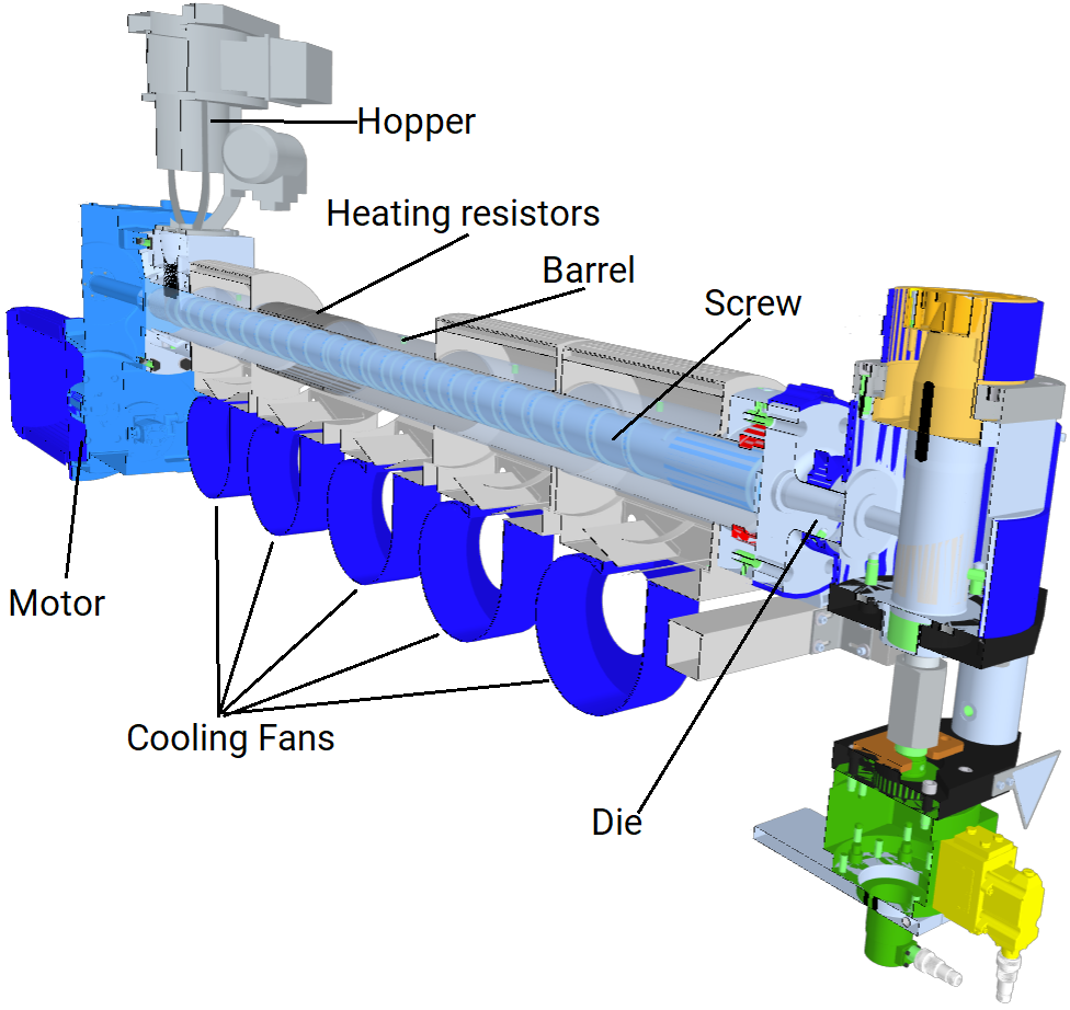
The purpose of this paper is to present the ExtruOnt ontology. It includes terms to describe 1) the main components of an extruder (e.g. the drive system), 2) the spatial connections between the extruder components (e.g. the filter is externally connected to the barrel), 3) the different features of the components (e.g. the power consumption of the motor is 40.5 kWh), 4) the 3D description of the position of the components (e.g. the feed hopper is located at point q(0,0,-1) in a 3D canvas), and, 5) the sensors that need to be used to capture indicators about the performance of that extruder (e.g the temperature sensor that captures the melting temperature of the polymer).
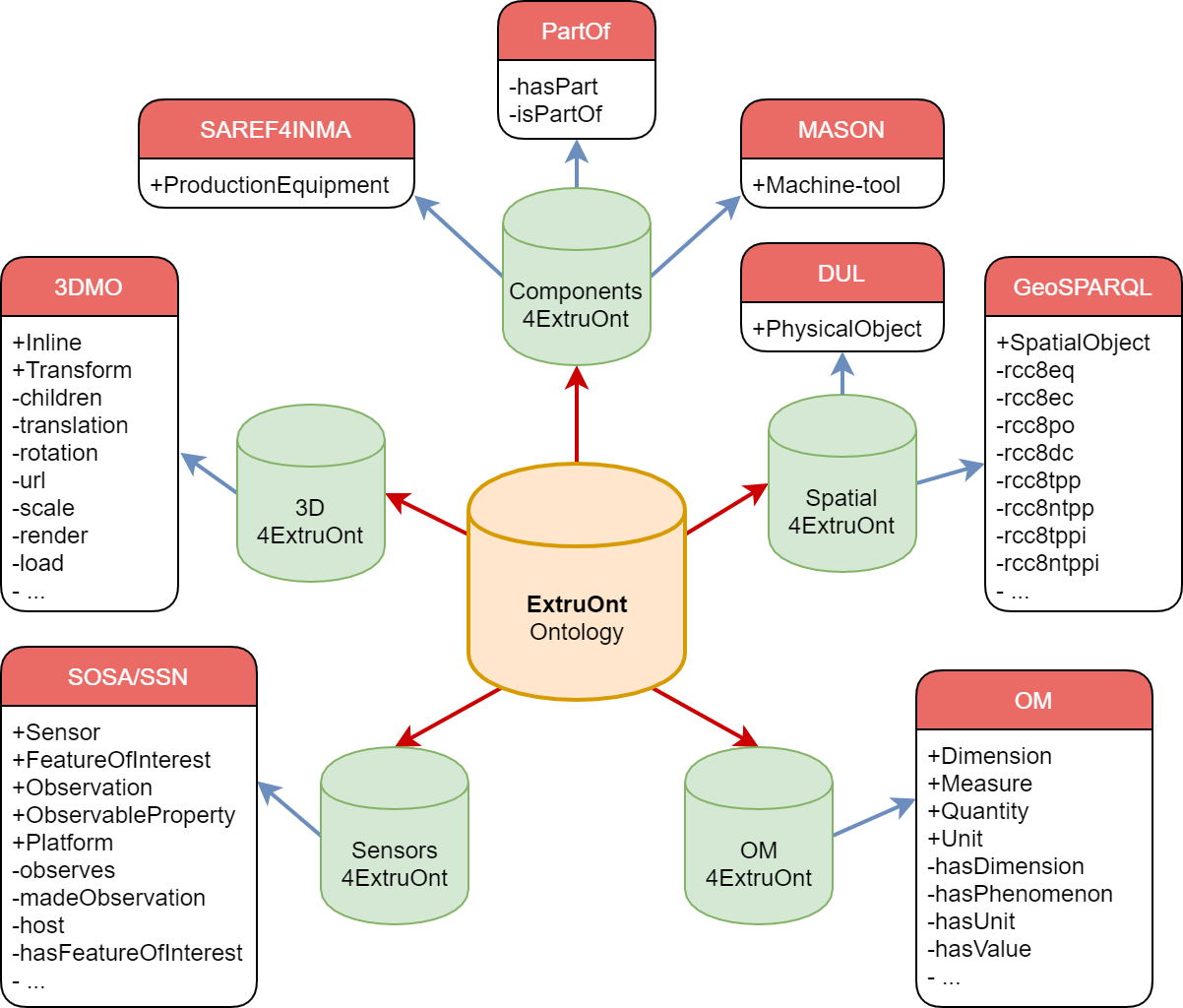
The ExtruOnt ontology has been implemented using OWL 2222https://www.w3.org/TR/owl2-overview/ and the Protégé333https://protege.stanford.edu/ [Musen (2015)] development environment. ExtruOnt is in line with concepts included in an ontology-based context model for industry presented in [Giustozzi et al. (2018)] and is aligned with several ontologies: the DUL ontology 444http://ontologydesignpatterns.org/wiki/Ontology:DOLCE+DnS_Ultralite, which models physical contexts; the MASON ontology, an upper ontology for representing the core concepts of the manufacturing domain [Lemaignan et al. (2006)]; SAREF4INMA [Daniele et al. (2018)], a SAREF [ETSI (2017)] extension for semantic interoperability in the industry and manufacturing domain; the GeoSPARQL ontology, which incorporates descriptions about Region Connection Calculus (RCC) [Perry and Herring (2012)]; the OM555https://enterpriseintegrationlab.github.io/icity/OM/doc/index-en.html ontology, the largest unit ontology [Rijgersberg et al. (2013)]; the 3D Modeling Ontology (3DMO), which maps the entire XSD-based vocabulary of the industry standard X3D666http://www.web3d.org/what-x3d-graphics (ISO/IEC 19775-19777) to OWL 2 [Sikos (2017)] and with the SOSA/SSN, which defines general concepts about sensors [Haller et al. (2018)].
Apart from the interest that the ExtruOnt ontology has in itself, the main contributions of the ExtruOnt ontology are the following: 1) Reusability. Its modular design facilitates the task of developing other ontologies for different types of manufacturing machines. The module that describes the components of an extruder could be replaced by another module that would describe another type of manufacturing machine, while alignments with other modules should be adapted to meet the requirements of the new type of machine. Moreover, the defined alignments of ExtruOnt ontology with upper ontologies such as DUL and MASON facilitate the task of modeling different manufacturing operations (e.g. customer orders, production plans); 2) Expressiveness of Spatial Connections. It incorporates a hierarchical description of possible relations in Region Connection Calculus and some custom-defined ones. Dealing with all those descriptions, more specific spatial relations can be defined and thus fine-grained results for questions can be provided.
Finally, the use of the ExtruOnt ontology as the core element of ontology-based systems, developed for Smart Manufacturing scenarios, can bring several benefits. For example, the development of an ontology-based Visual Query System will bring the following benefits to the different types of workers of a manufacturing plant:
-
•
Novice workers. The 3D rendering of an extruder machine obtained from descriptions in the ontology will allow novice workers to familiarize themselves with the extrusion process due to its similarity to reality.
-
•
Product Designers. The descriptions referring to the components of the extruder as well as the constraints regarding their spatial connections, positioning and features contained in the ontology will facilitate product designers the task of creating customized 3D images of extruder machines.
-
•
Domain experts. Ontology-based annotation of data captured by sensors will allow domain experts to perform an assisted exploration of data.
In the rest of this paper, we present first, distinct approaches that have been defined in the literature, related to two aspects considered during the development process of ExtruOnt: existing ontologies and ontology evaluation techniques. Then, we show some methodologies that have been proposed to adequately develop ontologies. Next, we illustrate the steps that we followed to develop the ExtruOnt ontology using the NeOn methodology [Suárez-Figueroa et al. (2012)] and the modules that constitute ExtruOnt. Later, we show the results of the evaluation process carried out considering two goals: domain coverage and quality of modeling. We finish with some conclusions and future work.
2 Related work
In the specialized literature several ontologies related to the Smart Manufacturing area can be found. Those ontologies were defined with distinct purposes and, therefore, describe different types of information related to that area. For example, the PSL (Process Specification Language) ontology [Grüninger (2009)] includes fundamental concepts for representing manufacturing processes. The foundational elements of the core of the PSL ontology are four primitive classes (activity, activity-occurrence, timepoint, object), three primitive relations (participates-in, before, occurrence-of) and two primitive functions (beginof, endof). The MASON (Manufacturing’s Semantics Ontology) ontology [Lemaignan et al. (2006)] is an upper ontology for representing what authors consider the core concepts of the manufacturing domain: products, processes and resources. As a result, the main classes of MASON are Entity (for specifying the product), Operation (for describing all processes linked to manufacturing) and Resource (for representing concepts regarding machine-tools, tools, human resources and geographic resources). The SIMPM (Semantically Integrated Manufacturing Planning Model) ontology [Šormaz and Sarkar (2019)] is an upper ontology that models the fundamental constraints of manufacturing process planning: manufacturing activities and resources, time and aggregation. MaRCO (Manufacturing Resource Capability Ontology) [Järvenpää et al. (2019)] defines capabilities of manufacturing resources. Its main class is Capability, which is specialized to cover both, simple capabilities (e.g. Fixturing, SpinningTool) and combined capabilities (those that require a combination of two or more simple capabilities, e.g. PickAndPlace, which requires FingerGrasping or Vacuum Grasping, Moving and Releasing). The MSDL (Manufacturing Service Description Language) ontology [Ameri and Dutta (2006)] allows to describe manufacturing services. More precisely, a Manufacturing Service is seen as a Service that is provided by a Supplier and that has some Manufacturing Capability, which is enabled by some Manufacturing Resource and delivered by some Manufacturing Process. The P-PSO (Politecnico di MilanoProduction Systems) ontology [Garetti and Fumagalli (2012)] considers three aspects in the manufacturing domain: the physical aspect (the material definition of the system), the technological aspect (the operational view of the system) and the control aspect (the management activities), for information exchange, design, control, simulation and other applications. Thus, its main classes are component, operation and controller, which model the aforementioned three aspects, as well as part, operator and subsystem. OntoSTEP (ONTOlogy of Standard for the Exchange of Product model data) [Barbau et al. (2012)] allows the description of product information mainly related to geometry. MCCO (Manufacturing Core Concepts Ontology) [Usman et al. (2011)] focuses on interoperability across the production and design domains of product lifecycle. It provides some core classes in categories such as ManufacturingProcess, ManufacturingFacility, ManufacturingResource and Feature. Finally, SAREF4INMA [ETSI (2017)] pursues favouring interoperability with industry standards. Some of its main classes are ProductionEquipment, Factory, Item and MaterialCategory.
Although some of the mentioned ontologies contain some general terms for representing the concept of industrial machine (e.g. Machine-tool in MASON, Device in MarCO, ProductionEquipment in SAREF4INMA), further specialization and characterization are needed for fitting our goal, that is, for describing specific industrial machine types with a fine-grained detail, and more particularly, extruder machines. The search on different ontology repositories (e.g. LOV [Vandenbussche et al. (2016)], Swoogle [Ding et al. (2004)], ODP [Gangemi and Presutti (2009)]) for an ontology that covered this domain yielded unsuccessful, and for that reason we built the ExtruOnt ontology following a well-established methodology.
Furthermore, considering the relevance of evaluating the quality and correctness of an ontology once it has been built, several evaluation approaches have been proposed in the specialized literature depending on the evaluation goal. The NeOn guidelines for carrying out the ontology evaluation activity [Sabou and Fernandez (2012)] identify the following goals of evaluation: domain coverage, quality of modeling, suitability for an application/task and adoption and use. Then, specific evaluation approaches need to be chosen depending on the selected goals. These approaches include, among others, comparing to a gold standard ontology [Maedche and Staab (2002)], comparing to unstructured or informal data [Brewster et al. (2004)], using human assessments [Lozano-Tello and Gomez-Perez (2004)], and using reasoners to assess the logical correctness of the ontology [Horridge et al. (2009)]. Another relevant work in the area of ontology evaluation is the one in [Vrandečić (2009)], where a common framework that considers quality criteria for aspects of ontology evaluation is presented. More precisely, it identifies the following criteria: accuracy, adaptability, clarity, completeness, computational efficiency, conciseness, consistency and organizational fitness. In the case of the proposed ExtruOnt ontology, some aspects considered in those works were taken into account during the evaluation process (see section 6).
3 Design Methodologies
Different methodologies such as On-To-Knowledge [Sure et al. (2004)], Diligent [Pinto et al. (2004)] and NeOn [Suárez-Figueroa et al. (2012)] can be found in the literature to adequately develop well-founded ontologies. On-To-Knowledge proposes a knowledge meta process consisting of five steps: feasibility study to determine whether to begin the actual development of the ontology; kickoff, where the requirements are specified and a semi-formal ontology description is developed; refinement, where the target ontology is obtained by refining and formalizing the semi-formal one; evaluation, where the evaluation of the ontology is done; and application and evolution, where the ontology is applied in the target system and maintained. On-To-Knowledge suggests reusing ontologies in the kickoff step if available, but does not provide any guidelines for it. Moreover, it does not deal with non-ontological resources nor other ontological resources such as ontology design patterns. Diligent proposes a process for a distributed development of ontologies that comprises five main steps: build, where an initial version of the ontology is built by different stakeholders such as domain experts, users, and knowledge and ontology engineers; local adaptation, where users adapt the ontology for their own purposes; analysis, where a control board analyses the local versions to detect similarities and decide which changes and requests are added to the next shared version of the ontology; revision, where the board revises the new version of the shared ontology; and local update, where users can update their local ontologies with information from the new version. This methodology does not detail the series of activities that should be followed during the build step, and moreover, it does not include guidelines for using neither ontological nor non-ontological resources in the development process. The NeOn methodology describes a set of nine scenarios that may occur when building an ontology, along with a list of activities that should be carried out in each scenario. Tightly related to those scenarios, it presents two ontology network life cycle models (waterfall and iterative-incremental) with several versions. The basic version is the Four-phase model, which includes the following phases: initiation, where the requirements are specified; design, where both an informal and a formal model of the ontology are created; implementation, where the formal model is implemented in an ontology language; and maintenance, where the ontology is used until errors or missing knowledge are detected. The NeOn methodology places special emphasis on reusing and re-engineering both ontological and non-ontological knowledge resources. Thus, more detailed versions of the basic model (e.g Five-phase model, Six-phase + Merging model) include as well one or more of the following phases, resulting in a variety of paths to develop an ontology: reuse, where existing ontological or non-ontological resources are added to the model; re-engineering, where those resources are modified to serve to the intended purpose; and merging, where ontologies are merged or alignments are established among ontological resources. The methodology includes thorough guidelines on how to perform all the mentioned activities.
4 Development of the ExtruOnt ontology
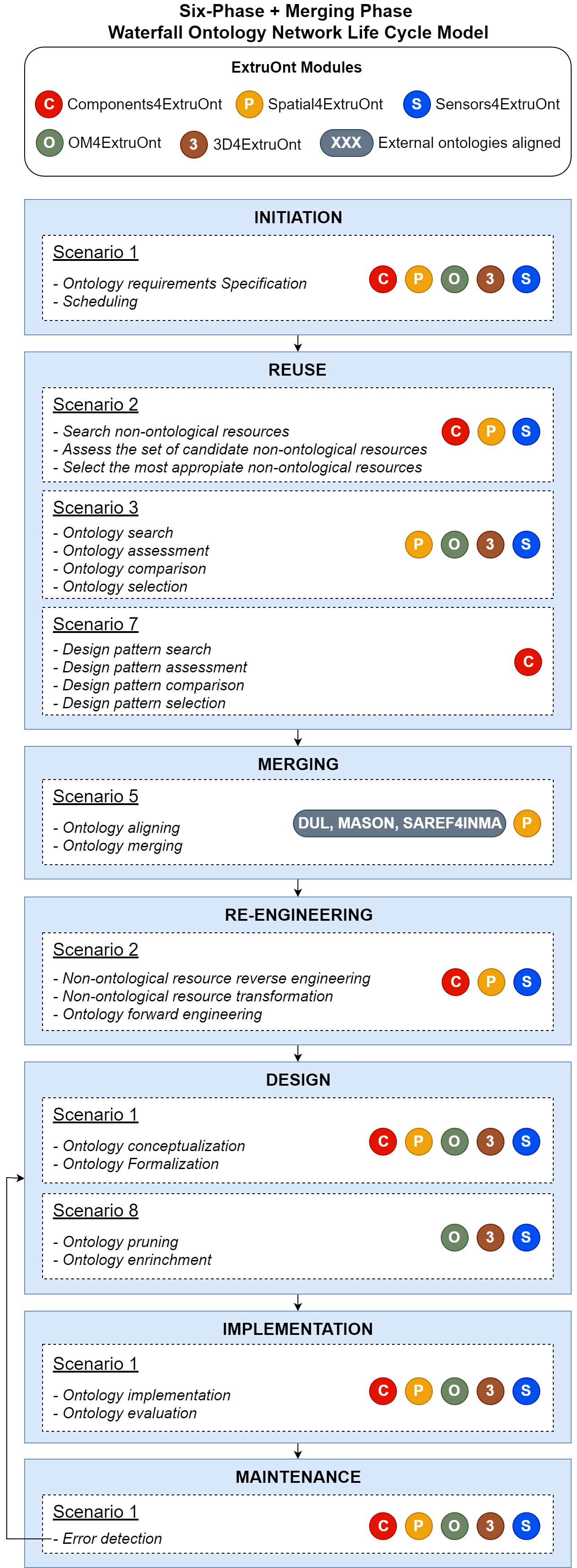
In order to develop the ExtruOnt ontology we selected the NeOn methodology. In our opinion, NeOn beats the other methodologies in these two aspects: on the one hand, the variety of scenarios that it takes into account, which results in a more flexible methodology, and on the other hand, the great detail in the description of the activities that need to be carried out when building the ontology. Furthermore, due to the requirements of ExtruOnt, which include reuse of ontological and no-ontological resources, re-engineering, merging, aligning with domain ontologies, implementation and evaluation among others, its development process fits with the Six-Phase + Merging Phase Waterfall Ontology Network Life Cycle Model. In figure 1 the phases of the aforementioned life cycle model along with scenarios, activities and modules of the ExtruOnt ontology involved in each scenario are indicated. These modules and their purpose are explained in section 5. The different phases of the life cycle model are explained below.
4.1 Initiation
In collaboration with the R&D director of a company that manufactures extruder machines, we created the Ontology Requirements Specification Document (ORSD) that contains among others, the purpose of the ExtruOnt ontology, its scope and the Competency Questions (CQs), see Table 1. After a detailed analysis of those questions, it was noticed that they referred to five different dimensions regarding information related to extruders. Thus, the questions were classified in the following five groups, one for each dimension: the components of an extruder, the spatial connections between those components, their features, their 3D description and the sensors that capture information about several indicators (Scenario 1).
| 1. | Purpose |
|---|---|
| The purpose of the ExtruOnt ontology is to provide a reference model for the physical representation of extruder machines and the time series data gathered from their sensors, allowing to describe the extruder components, their position with respect to other components and the data obtained from sensing devices. | |
| 2. | Scope |
| The ontology will focus on general purpose extruder machines. | |
| 3. | Implementation language |
| The ontology has to be implemented in a formalism that allows classification of classes and realization between instances and classes. | |
| 4. | Intended users |
| • User 1: Novice workers. • User 2: Product designers. • User 3: Domain Experts. | |
| 5. | Intended uses |
| • Use 1: To describe different models of extruders. • Use 2: To help the process of identifying the extruder components and their location. • Use 3: To help to select the optimal extruder for a specific product. • Use 4: To recognize differences between extruder models. • Use 5: To improve user interaction with the different sensing devices in the extruder and the gathered data. | |
| 6. | Ontology requirements |
| (6.a) Non-functional requirements (not applicable) | |
| (6.b) Functional requirements: Groups of competency questions | |
| • CQG1: Extruder components-related competency questions: – CQ1.1: How many heater bands does the extruder E01 have? – CQ1.2: What kind of extrusion head does the extruder E02 have? – CQ1.3: Is the machine E03 a single or double screw extruder? – CQ1.4: Is the extruder E04 powered by an AC motor? – CQ1.5: Is this extruder E05 suitable to process plastic pellets? – CQ1.6: Can the extruder E06 process multiple polymers? – … • CQG2: Spatial connections-related competency questions: – CQ2.1: With which components are the filters FIL01 connected? – CQ2.2: Which components overlap the barrel BAR01? – CQ2.3: Which components are disconnected from the motor M01? – CQ2.4: Which components are monitored in the drive system DS01? – CQ2.5: How many sensors does the barrel BAR02 have? – … • CQG3: Features-related competency questions: – CQ3.1: What is the diameter of the barrel BAR03? – CQ3.2: What are the optimal operating conditions of the screw SCR01? – CQ3.3: What is the maximum torque produced by the motor M02? – CQ3.4: Does the extruder E07 fit in a space 3 meters wide by 5 meters long? – CQ3.5: What is the bottles-per-hour production rate of the extruder E08? – … • CQG4: 3D positioning-related competency questions: – CQ4.1: Which components of extruder E11 can not be located in a 3D canvas? – CQ4.2: What are the modeling and position of the feed hopper FH01? – … |
| • CQG5: Sensors and observations-related competency questions: – CQ5.1: What properties are observed by the sensors located in the extrusion head EH01? – CQ5.2: What is the unit of measurement used by the motor consumption sensor MCS01? – CQ5.3: Where is the melting temperature sensor located in extruder E08? – CQ5.4: What is the identifier of the temperature sensor in extrusion head EH02? – CQ5.5: When was the first and last observation made by sensor SN01? – CQ5.6: What was the average, maximum and minimum value of the observations in a day for the sensor SN02? – CQ5.7: How many observations from torque sensor SN03 are outside the optimal values? – CQ5.8: how long was the maximum period of extruder E09 inactivity during the last week? – CQ5.9: At what times during August 21st, 2018 and August 22nd, 2018 did the melting temperature exceed the maximum optimal operational value in extruder E10? – … | |
| 7. | Pre-glossary of terms |
| Extruder, feed system, observation, sensor, tangential proper part, measure, 3D canvas … |
4.2 Reuse
Due to the fact that the search for an ontology that covered all these dimensions was unsuccessful, we focused on searching both ontological and non-ontological resources for each dimension.
In this subsection, we present the non-ontological and ontological resources used to describe the aforementioned dimensions.
-
•
Components of an extruder: In order to describe the components, we relied on the one hand, on non-ontological resources existing in the specialized literature and mainly in a full chapter dedicated to the extruder and its equipment that appears in [Giles et al. (2004)]. Moreover, due to the complexity of the extrusion head, another non-ontological resource was used as a reference to represent the features of this component. In [Sikora (2008)], a thorough explanation of the extrusion head design and applications is presented, categorizing the extrusion head depending on the position and the type of extrudate obtained (Scenario 2). On the other hand, the PartOf777http://ontologydesignpatterns.org ontology design pattern was selected in order to specify parthood between the extruder and its components, as well as between different parts that constitute each component (Scenario 7).
-
•
Spatial connections between components: In the specialized literature can be found the Region Connection Calculus (RCC) [Randell et al. (1992), Cohn et al. (1997)], which is intended to represent the spatial relations between objects and facilitate reasoning over those relations. There are multiple representations of the RCC. The main one is RCC8, which consists of 8 basic relations that are possible between two regions. Different ontologies have tried to represent the RCC descriptions (GeoSPARQL[Perry and Herring (2012)], Spatial Relations Ontology888http://data.ordnancesurvey.co.uk/ontology/spatialrelations/, NeoGeo Spatial Ontology 999http://geovocab.org/doc/neogeo/). We selected the GeoSPARQL ontology, which models the RCC8 relations, because it is the base for the other spatial ontologies (Scenario 3).
-
•
Features of the components: Based on a work that evaluates ontologies of measurements [Keil and Schindler (2018)], two ontologies were considered: QUDT101010http://www.linkedmodel.org/catalog/qudt/1.1/index.html [Hodgson and Keller (2011)] and OM111111https://enterpriseintegrationlab.github.io/icity/OM/doc/index-en.html [Rijgersberg et al. (2013)]. QUDT is the result of a NASA-sponsored initiative to formalize Quantities, Units of Measure, Dimensions and Types, and it is categorized as a medium sized ontology. OM is an ontology that allows to model concepts and relations in the context of food research and it was the largest unit ontology compared. In the aforementioned evaluation, multiple issues were found in QUDT ontology like reasoning impossibility, duplicated units, wrong specifications, typing errors, etc. Moreover, only English labels were added and, according to the article, the reported issues remain unsolved. On the other hand, OM shared some issues with QUDT like reasoning impossibility, wrong dimension values, typing errors, but the reported issues have been corrected and labelling can be found in Dutch and Chinese for a subset of individuals. Equally important, more concepts can be found in OM, so this was the selected ontology (Scenario 3).
-
•
3D representation of components: We selected the 3D Modeling Ontology (3DMO) [Sikos (2017)] because this ontology maps the entire XSD-based vocabulary of the industry standard X3D121212http://www.web3d.org/what-x3d-graphics (ISO/IEC 19775-19777) to OWL 2. Therefore, it can be used for the representation, annotation, and efficient indexing of 3D models (Scenario 3).
-
•
Sensors for capturing information about indicators: We did not find any ontological resource that defines the specific types of sensors that are used to monitor extruders. However, the well known SOSA/SSN[Haller et al. (2018)] ontology defines general concepts about sensors, which can be specialized with information obtained from non-ontological resources about extruders [Giles et al. (2004)] to reflect the specificities of the extrusion domain (scenario 3).
4.3 Merging
To guarantee semantic interoperability, the ExtruOnt ontology is aligned with other domain ontologies such as: 1) DUL, an upper ontology created to provide a set of concepts to facilitate interoperability among ontologies; 2) MASON, an upper ontology for representing the core concepts of the manufacturing domain and 3) SAREF4INMA, a SAREF extension for industry and manufacturing (scenario 5). The selection of these ontologies was carried out taking into account different key factors such as domain, use, maintenance, acceptance, popularity and coverage. For example, in the selection of MASON, other different ontologies were considered: MaRCO, whose approach is oriented to machine capabilities and, thus, out of our scope; MSDL, with a large amount of concepts focused on processes and resources but leaving products aside; SIMPM, with few concepts and focused only on the processes; and finally, PSL, P-PSO, MCCO and OntoSTEP whose OWL definitions could not be found. On the contrary, MASON defines a meaningful categorization of products, processes and resources, it has been widely reviewed [Cao et al. (2018)] and it is currently available. The terms used in the ontology alignment are presented in section 5.1.
Concerning to the spatial connection between components, we realized that using only the GeoSPARQL ontology was not sufficient for answering competency question CQ2.2. Thus, a twofold approach was used: in addition to the GeoSPARQL ontology, information about other RCC spatial relations obtained from the aforementioned non-ontological RCC resources was incorporated (scenario 5).
4.4 Re-engineering
A re-engineering process was carried out to transform the non-ontological resources mentioned previously into conceptual models, analyzing the structure of the resource (chapters, subsections, connections, order, etc.). Once the conceptual model for each resource had been created, they were used as input of the design phase. (Scenario 2).
4.5 Design
The modularization of ontologies facilitates the development, reuse and maintenance of an ontology. In addition, it conforms to the dimensionality approach obtained from the ORSD analysis. Therefore, each of the five dimensions was represented through a module: the components of an extruder (components4ExtruOnt), the spatial connections between those components (spatial4ExtruOnt), their features (OM4ExtruOnt), their 3D description (3D4Extru-Ont) and the sensors that capture information about several indicators (sensors4ExtruOnt), which altogether form the ExtruOnt131313http://bdi.si.ehu.es/bdi/ontologies/ExtruOnt/ExtruOnt.owl ontology (Scenario 1). The key features of each module are presented in depth in section 5.
OM, SOSA/SSN and 3DMO ontologies contain a wide range of concepts that belong to the domains they represent, however, due to the specific domain we wanted to model, a pruning process was carried out for these ontologies keeping only those concepts and descriptions that are relevant, favoring lightness, cleanliness and maintenance of the ontology (Scenario 8). Additionally, the pruned SOSA/SSN ontology was enriched with specialized concepts drawn from the conceptual model (see section 5.5).
4.6 Implementation
A formal model expressed in a Description Logic was generated and implemented in OWL 2 DL Web Ontology Language using Protégé [Musen (2015)] (Scenario 1). Later, a wide evaluation of the ontology was done which is presented in section 6, describing the different considered approaches.
4.7 Maintenance
The maintenance phase is currently undergoing. Once an error is detected, the ontology will be taken to the design phase to be corrected, as stipulated in the Waterfall ontology network life cycle model.
5 Ontology modules
As said before, ExtruOnt is divided in five modules aiming to describe several characteristics of an extruder machine (see Fig. 2).
In the following, the key features of each module are presented.
5.1 components4ExtruOnt
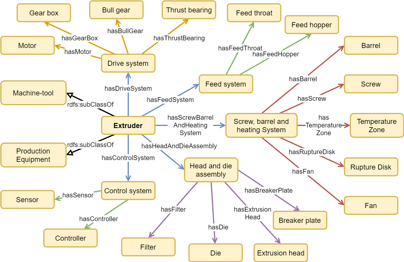
The components4ExtruOnt141414http://bdi.si.ehu.es/bdi/ontologies/ExtruOnt/components4ExtruOnt.owl module is the main module of the ExtruOnt ontology and is intended to describe the components of an extruder. According to [Giles et al. (2004)], five major systems can be distinguished in an extruder:
-
•
Drive system.
-
•
Feed system.
-
•
Screw, barrel and heating system.
-
•
Head and die assembly.
-
•
Control system.
Moreover, the components of each one of these systems are explained. For instance, the drive system is composed of motor, gear box, bull gear, and thrust bearing; and the head and die assembly contains the head, die/nozzle, breaker plate and filters/screens. This analysis of the components of the extruder was used as base to create the components4ExtruOnt module.
A new main class called Extruder was created for representing the extrusion machine, while the connections between the extruder and its systems and components were made using the hasPart object property of the PartOf151515http://www.ontologydesignpatterns.org/cp/owl/partof.owl ontology design pattern. Moreover, custom-made specializations of hasPart were created to relate specific components, e.g., hasBarrel, hasScrew and hasHeaterBand. The parthood relations of the extruder and its components are shown in Fig. 3. To facilitate integration with other domain ontologies, the terms saref4inma:ProductEquip- ment161616https://w3id.org/def/saref4inma and
MASON:Machine-tool171717https://sourceforge.net/projects/mason-onto/
were included as superclasses of Extruder.
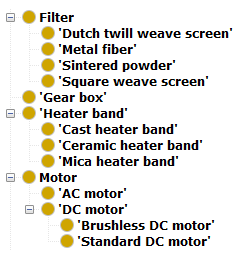
Moreover, the specialization of each component was represented using rdfs:subClassOf relations. An example is illustrated in Fig. 4.
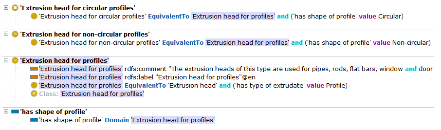
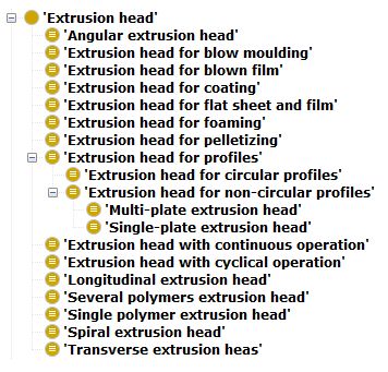
With respect to the extrusion head, the classification that can be found in [Sikora (2008)] was used to provide a detailed representation of this component. Figs. 5 and 6 exemplify this representation.
Among others, the following competency questions are resolved with the components4ExtruOnt module:
-
•
CQ1.1: How many heater bands does the extruder E01 have?
-
•
CQ1.2: What kind of extrusion head does the extruder E02 have?
-
•
CQ1.3: Is the machine E03 a single or double screw extruder?
-
•
CQ1.4: Is the extruder E04 powered by an AC motor?
-
•
CQ1.5: Is this extruder E05 suitable to process plastic pellets?
-
•
CQ1.6: Can the extruder E06 process multiple polymers?
A SPARQL query to answer the competency question CQ1.4 is as follows181818We assume that the query is executed after inferences are provided by a reasoner (This applies for all the examples in this paper.):
PREFIX : <http://bdi.si.ehu.es/bdi/ontologies/ ExtruOnt/Extruder01#>PREFIX rdf: <http://www.w3.org/1999/02/ 22-rdf-syntax-ns#>PREFIX c4e: <http://bdi.si.ehu.es/bdi/ontologies/ ExtruOnt/components4ExtruOnt#>PREFIX p: <http://www.ontologydesignpatterns.org/ cp/owl/partof.owl#>ASK { :E04 p:hasPart ?motor01. ?motor01 a c4e:AC_motor }
As a result, the description of the extruder in the components4ExtruOnt module will help novice workers to recognize its different sections and components. Moreover, it will help domain experts to formulate queries, according to their needs, related to the amount of components and their types.
5.2 spatial4ExtruOnt
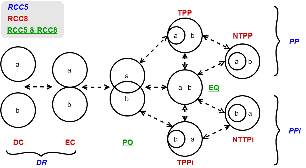
The main representation of RCC is RCC8, which consists of 8 basic relations that are possible between two regions: Equal (EQ), Disconnected (DC), Externally Connected (EC), Partially Overlapping (PO), Tangential Proper Part (TPP), Non-Tangential Proper Part (NTPP), Tangential Proper Part inverse (TPPi) and Non-Tangential Proper Part inverse (NTTPi). A stripped down version of RCC8 is RCC5, which consists of 5 relations: Equal (EQ), Discrete (DR), Partially Overlapping (PO), Proper Part (PP) and Proper Part inverse (PPi). The graphical representation of RCC5 and RCC8 relations with their mappings are shown in Fig. 7.
For the spatial4ExtruOnt191919http://bdi.si.ehu.es/bdi/ontologies/ExtruOnt/spatial4ExtruOnt.owl module, a submodule of the GeoSPARQL ontology was used, which contains the SpatialObject main class and the object properties referencing to the RCC8 relations. To encourage semantic interoperability, the term PhysicalObject
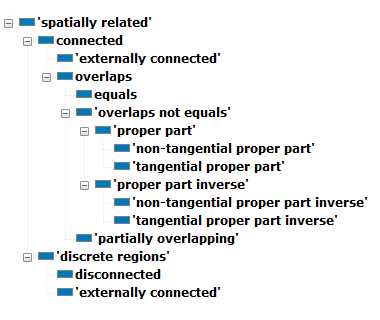
from DUL ontology202020http://ontologydesignpatterns.org/wiki/Ontology:DOLCE+DnS_Ultralite was included as a superclass of SpatialObject. Moreover, a hierarchical object property representation was made including RCC8 relations connected to RCC5 ones, and some more general custom-defined properties. For example, rcc8tpp (tangential proper part) is a subproperty of rcc5pp (proper part) and, in the same way, rcc5pp is a subproperty of the custom-made overlapsNotEquals object property. Another example is the following: when two objects overlap, three possible situations can occur: 1) A is equal to B, 2) A partially overlaps B and 3) A overlaps but is not equal to B. This is represented with the overlaps object property and three subproperties: rcc8eq (equals), rcc8po (partially overlapping) and overlapsNotEquals (overlaps but not equal). This hierarchy allows a fine-grained classification of spatial relations and can provide detailed results to general questions, e.g., the answer to the question about the objects that overlaps object X will return those objects that are equals, partially overlapping and proper part of object X. The object property hierarchy is shown in Fig. 8.
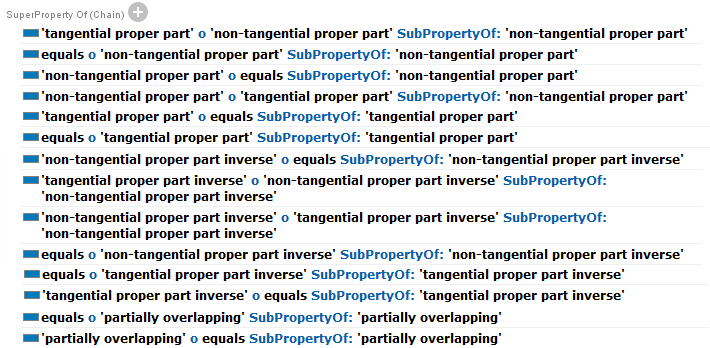
RCC8 also defines a composition table where the possible relations between an object A and an object C are indicated based on the relation between object A and B, and the relation between object B and C. However, the OWL 2 DL expressivity level is not sufficient to represent the full table, and for that reason, in spatial4ExtruOnt only compositions that yield a single result for the type of relation between objects A and C have been defined in the ontology, more precisely by means of property chains (see Fig. 9 ).
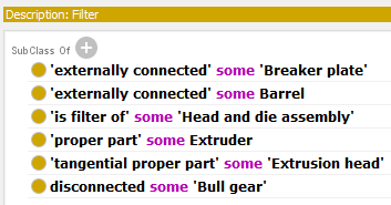
Once the spatial4ExtruOnt module was added to ExtruOnt, it was possible to describe the spatial connections between the components of the extruder. The classes that describe single components were declared as subclasses of the SpatialObject class and the relations between components were made. For example: the filter is externally connected to the barrel and the breaker plate, and it is a tangential proper part of the extrusion head (Fig. 10).
With the spatial4ExtruOnt module, it is possible to answer several competency questions. These are some of them:
-
•
CQ2.1: With which components are the filters FIL01 connected?
-
•
CQ2.2: Which components overlap the barrel BAR01?
-
•
CQ2.3: Which components are disconnected with the motor M01?
-
•
CQ2.4: Which components are monitored in the drive system DS01?
-
•
CQ2.5: How many sensors does the barrel BAR02 have?
The CQ2.2 competency question is resolved with the following SPARQL query:
PREFIX : <http://bdi.si.ehu.es/bdi/ontologies/ ExtruOnt/Extruder01#>PREFIX s4e: <http://bdi.si.ehu.es/bdi/ontologies/ ExtruOnt/spatial4ExtruOnt#>SELECT DISTINCT ?componentWHERE { {?component s4e:overlaps :BAR01} UNION {:BAR01 s4e:overlaps ?component}}
The spatial4ExtruOnt module will allow novice workers to understand the spatial connections between the different components of an extruder. Furthermore, it will help product designers and domain experts to define the distribution of the components, e.g., the position of the sensors in the head and die assembly.
5.3 OM4ExtruOnt
The objective of the OM4ExtruOnt212121http://bdi.si.ehu.es/bdi/ontologies/ExtruOnt/OM4ExtruOnt.owl module is to provide the terms that are necessary to describe the features of the components. This is an important step in the representation of the extruder, as single components could have different characteristics: a barrel could have different dimensions and manufacturing materials.
A submodule of the OM ontology was used to create OM4ExtruOnt, where only the concepts useful for characterizing the components of the extruder and process were taken into account. As stated before, due to the fact that OM is an ontology in the context of food research, it is common to find concepts like NumberColor1 and NumberRottenFlowers to refer to the avocado color and flower status respectively. Consequently, these concepts were removed keeping only concepts like temperature, speed, size, etc.
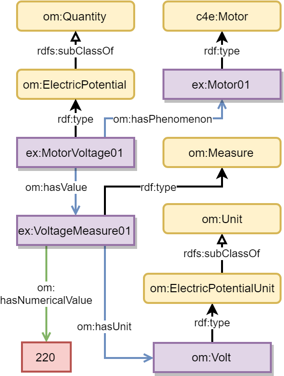
The elements of the OM4ExtruOnt module can be connected to the elements of the components4ExtruOnt module by means of the object property hasPhenom- enon, which links a measure made for a feature with the object to which the measure applies. For example, in Fig. 11 a measure (ex:VoltageMeasure01) of the motor voltage (ex:MotorVoltage01) of a specific motor (ex:Motor01) is represented, which in this case takes the value of 220 volts.
Once the features of the components are defined using the OM4ExtruOnt module, it is possible to answer more competency questions, such as:
-
•
CQ3.1: What is the diameter of the barrel BAR03?
-
•
CQ3.2: What are the optimal operating conditions of the screw SCR01?
-
•
CQ3.3: What is the maximum torque produced by the motor M02?
-
•
CQ3.4: Does the extruder E07 fit in a space 3 meters wide by 5 meters long?
-
•
CQ3.5: What is the bottles-per-hour production rate of the extruder E08?
To solve the CQ3.3 competency question a SPARQL query was designed:
PREFIX : <http://bdi.si.ehu.es/bdi/ontologies/ ExtruOnt/Extruder01#>PREFIX rdf: <http://www.w3.org/1999/02/ 22-rdf-syntax-ns#>PREFIX om: <http://www.ontology-of-units-of- measure.org/resource/om-2/>SELECT ?motorTorque01 ?torqueMeasure ?value ?unitWHERE { ?motorTorque01 a om:Torque. ?motorTorque01 om:hasPhenomenon :M02. ?motorTorque01 om:hasValue ?torqueMeasure. ?torqueMeasure om:hasUnit ?unit; om:hasNumericalValue ?value.}
On the one hand, the definition of the features of the components made on the OM4ExtruOnt module will contribute to the novice workers’ awareness of the maximum operating condition of the components. On the other hand, it provides a tool for domain experts to annotate the features of the components, gathered from the design process facilitating the preparation of their specification.
5.4 3D4ExtruOnt
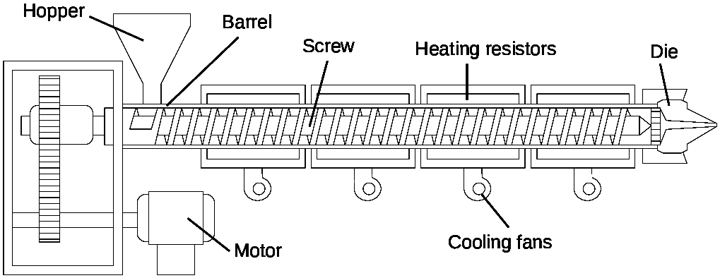
The graphic representation of an extruder permits to visually understand/observe the positioning of each component that is part of it. Many images of extruders can be found in books, articles, brochures and websites. However, the limitations of a 2D environment makes it difficult to visualize the exact position of the components. Thus, the understanding of an extruder is limited due to the lack of interaction, and the viewer is restricted to the bi-dimensional expressiveness of the author (Fig. 12). On the contrary, a 3D representation of an extruder allows to improve the viewer’s interaction, facilitating to move, rotate, zoom in and zoom out. This advantage provides each user with a personalized experience (Fig. 13).
The purpose of the 3D4ExtruOnt222222http://bdi.si.ehu.es/bdi/ontologies/ExtruOnt/3D4ExtruOnt.owl module is to provide terms for describing the position of each single component in the extruder, in a way that each single component model can be located in a 3D canvas.
X3D is a royalty-free open standards file format and run-time architecture to represent and communicate 3D scenes and objects, which is approved for the International Standards Organization (ISO). With a set of rich features, X3D can be used in scientific visualization, CAD and architecture, training and simulation, etc. and supports:
-
•
3D graphics and programmable shaders
-
•
2D graphics
-
•
CAD data
-
•
Animation
-
•
User interaction
-
•
Navigation
The selected 3DMO ontology contains a complete X3D definition. To build the 3D4ExtruOnt module, only the section referring to the 3D object positioning was selected.
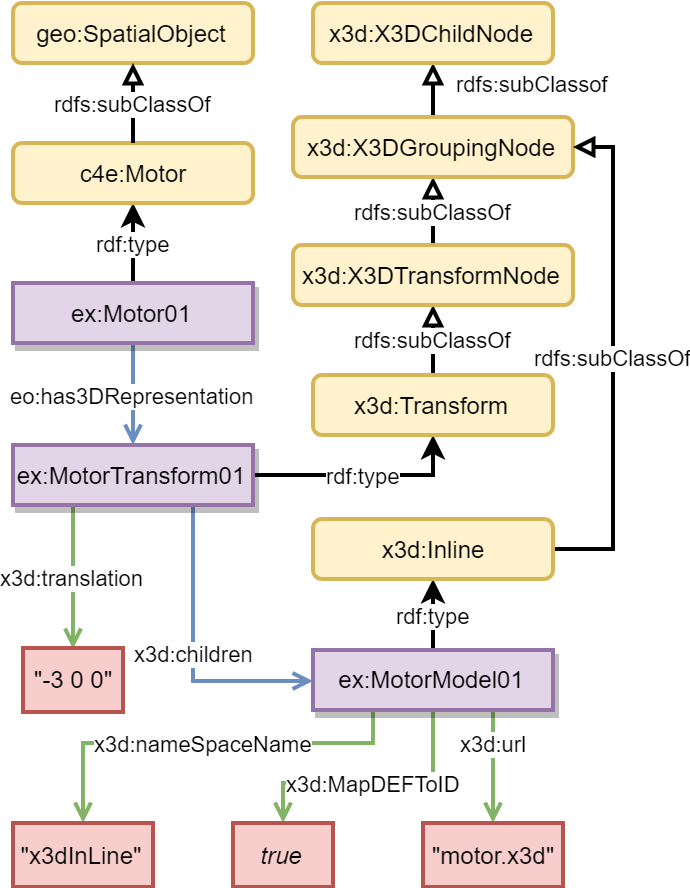
To connect the elements of the 3D4ExtruOnt module with the elements of the components4ExtruOnt module, a new has3DRepresen- tation object property was included, whose range is the X3D Transform class and the domain is the SpatialObject class, previously mentioned.
Transform class provides the translation property where the x, y and z coordinates, referring to the position of a 3D model in a canvas, can be specified. The Inline class allows to load different external 3D file formats (obj, stl, collada, fbx, etc.) by using the url property to specify the path to the resource location.
An example of the 3D positioning of the motor is shown in Fig. 14.
Now, it is possible to answer competency questions referring to 3D object positioning, for example:
-
•
CQ4.1: Which components of extruder E11 can not be located in a 3D canvas?
-
•
CQ4.2: What are the modeling and position of the feed hopper FH01?
The following SPARQL query can be used to answer the competency question CQ4.2:
PREFIX : <http://bdi.si.ehu.es/bdi/ontologies/ ExtruOnt/Extruder01#>PREFIX rdf: <http://www.w3.org/1999/02/ 22-rdf-syntax-ns#>PREFIX e: <http://bdi.si.ehu.es/bdi/ontologies/ ExtruOnt/ExtruOnt#>PREFIX x3d: <http://purl.org/ontology/x3d/>SELECT ?position ?nameSpace ?id ?urlWHERE { :FH01 e:has3DRepresentation ?hopper3d. ?hopper3d a x3d:Transform; x3d:translation ?position; x3d:children ?model3d. ?model3d a x3d:Inline; x3d:nameSpaceName ?nameSpace; x3d:MapDEFToID ?id; x3d:url ?url.}
The 3D4ExtruOnt module will help domain experts in the design process of components, by providing the required information to position 3D models of components in a scene. Moreover, the detection of faults or collisions will be facilitated. Furthermore, it will help novice workers to understand the physical appearance of single components and recognize them in real-world scenarios.
5.5 sensors4ExtruOnt
This module is intended to enable domain experts to gain a greater value and insights out of the captured data from the sensors of the extruders, in order to keep trace of the performance of the extruder and allowing to detect possible future faults.
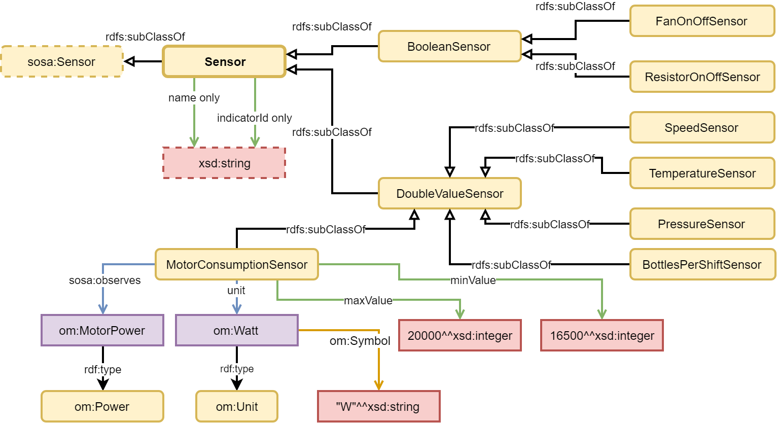
The sensors4ExtruOnt232323http://bdi.si.ehu.es/bdi/ontologies/ExtruOnt/sensors4ExtruOnt.owl module imports the SOSA/ SSN [Haller et al. (2018)] and OM4ExtruOnt ontologies. The class Sensor was created as a specialization of sosa: Sensor . Two properties were added to this class: indicatorId (the identifier of the sensor) and sensorName (the name of the sensor). Moreover, two main subclasses of Sensor were defined: Bool- eanSensor and DoubleValueSensor to represent sensors that capture true/false data and numerical data respectively.
Finally, these two subclasses were specialized for describing more specific type of sensors, more precisely sensors for observing: whether a resistor is on or off, whether a fan is on or off, the level and composition of the additive, the number of bottles made in a shift, the feed rate of the polymer, the melting temperature of the polymer, the power consumption of the motor, the pressure in the pressurized zones of the extruder, the speed of the rotational components, the temperature, the thickness of the extrudate and the viscosity of the extrudate.
The observable property for each sensor type is indicated by sosa:observes. For example, the observable property of a MotorConsumptionSensor is Power (imported from OM4ExtruOnt) and its unit is Watt, an individual of PowerUnit.
Each sensor type is related to the type of observation that it makes through the sosa:madeObservation property. For each observation, its value and timestamp are indicated by properties sosa:hasSimpleResult and sosa:ResultTime respectively.
The annotations made in the data and the descriptions in the module can be used to generate a customized and semantically enriched chart to visualize the data. For example, when a sensor is defined as an individual of MotorConsumptionSensor class, it can be inferred that it captures values in Watts, its symbol is W and its optimal operational values are between 15,600 and 20,000 units. This information can be used to select the most convenient visual representation of the data, improving the analysis and user experience.
An excerpt of the module can be found in Fig. 15.
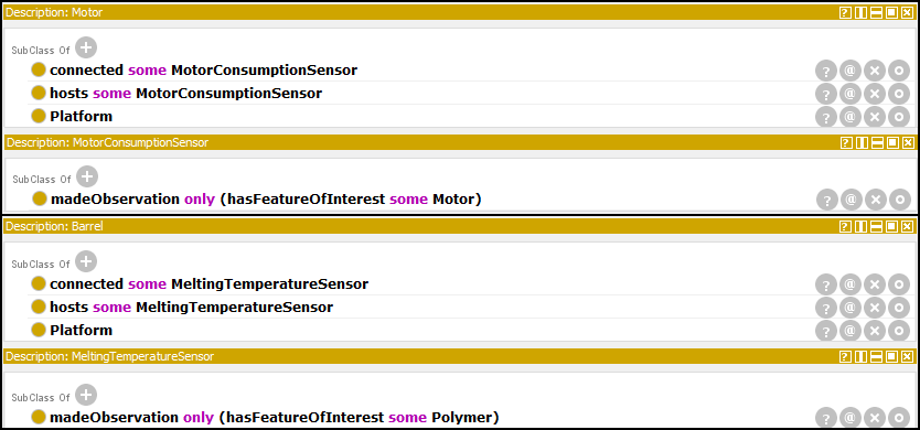
In order to indicate the spatial location of a sensor in the extruder the terms described in the module spatial4ExtruOnt can be used. In addition, the parts of the extruder (described in the module components4ExtruOnt) that host sensors can be seen as sosa:Platforms, and linked to them via the object property sosa:hosts. Finally, the feature of interest of the observations of each type of sensors has been indicated using the property sosa:hasFeatureOf- Interest. For example, in the case of a MotorCon- sumptionSensor the motor of the extruder is both its platform and its feature of interest, while in the case of a MeltingTemperatureSensor the platform is the barrel of the extruder and its feature of interest is the polymer used in that extrusion process (see Fig. 16).
With the addition of this module, a selection of competency questions can be solved, among others:
-
•
CQ5.1: What properties are observed by the sensors located in the extrusion head EH01?
-
•
CQ5.2: What is the unit of measurement used by the motor consumption sensor MCS01?
-
•
CQ5.3: Where is the melting temperature sensor located in extruder E08?
-
•
CQ5.4: What is the identifier of the temperature sensor in extrusion head EH02?
-
•
CQ5.5: When was the first and last observation made by sensor SN01?
-
•
CQ5.6: What was the average, maximum and minimum value of the observations in a day for the sensor SN02?
-
•
CQ5.7: How many observations from torque sensor SN03 are outside the optimal values?
-
•
CQ5.8: How long was the maximum period of extruder E09 inactivity during the last week?
-
•
CQ5.9: At what times during August 21st, 2018 and August 22nd, 2018 did the melting temperature exceed the maximum optimal operational value in extruder E10?
A SPARQL query to answer the CQ5.9 competency question is presented as follows:
prefix :<http://bdi.si.ehu.es/bdi/ontologies/ ExtruOnt/Extruder01#>prefix sosa: <http://www.w3.org/ns/sosa/>prefix xsd: <http://www.w3.org/2001/XMLSchema#>prefix sn4e: <http://bdi.si.ehu.es/bdi/ontologies/ ExtruOnt/sensors4ExtruOnt#>PREFIX p: <http://www.ontologydesignpatterns.org/ cp/owl/partof.owl#>select ?resultValue ?resultTimewhere { :E10 p:hasPart ?barrel01. ?barrel a c4e:Barrel . ?barrel sosa:hosts ?meltingTempSn01 . ?meltingTempSn01 a sn4e:MeltingTemperatureSensor; sosa:madeObservation ?obs; sn4e:maxValue ?maxValue. ?obs sosa:hasSimpleResult ?resultValue ; sosa:resultTime ?resultTime . filter(?resultValue > ?maxValue) . filter((xsd:dateTime(?resultTime) >= "2018-08-21T00:00:00.000Z"^^xsd:dateTime) && (xsd:dateTime(?resultTime) <= "2018-08-22T23:59:59.999Z"^^xsd:dateTime))}order by asc(?resultTime)
The sensors4ExtruOnt module allows domain experts to analyze and keep trace of sensors data in a structured way, retaining important relations and properties between the data, sensors and components of an extruder, which can be valuable in a future failure prediction process.
6 Evaluation
Once the ExtruOnt ontology was developed, in order to check its quality, two evaluation goals were considered: Domain coverage to see in which extent it covered the considered extrusion domain, and Quality of the modeling in terms of the design and development process and in terms of the final result. The third goal identified by NeOn (Suitability for an application/task) will be considered once software artifacts whose core element is the ExtruOnt ontology (see section 7) are built. Moreover, the passing of time will allow to evaluate the ontology regarding the goal of Adoption and use. During the evaluation process, the ontology was also assessed by three types of persons: 1) A R&D director of a company that develops machines that produce bottles based on an extrusion process, who we work closely with. This person also provides us real data captured from the machines developed by his company. 2) A director of an IBDS (Industrial Big Data Services) Provider company. IBDS is an ITS (Information Technology Supplier) company that supplies manufacturers with the required technology and services to smartize their manufacturing businesses. Thus, IBDS Providers constitute a fundamental agent in industrial scenarios where there is an interest in adopting Smart Manufacturing approaches. 3) An expert in developing and managing ontologies who works in a technology center specialized in the industrial domain.
6.1 Domain coverage
Using the non-ontological resources and reusing some other existing ontologies related to the dimensions considered in the ontology, a first version of ExtruOnt ontology was built. Then, after a rigorous discussion process with the three experts, who evaluated the correctness and usefulness of the described information in the ontology, it was redefined and some new terms were incorporated and some others were eliminated. Thus, R&D director of the company, based on his knowledge about the extrusion process, evaluated the semantic quality of the ontology. For example, he suggested to eliminate the three types of categories that we defined related to type of heads (that appear in the non-ontological resource regarding extrusion heads) and refer them through the definition of new features in the existing extrusion head term (for example, shape of profile and quantity of plates) in order to avoid some ambiguities in the representation.The director of an IBDS, based on his acquired knowledge by providing smart manufacturing services to different types of manufacturing companies, evaluated to what extent the ontology could be adapted and used in other manufacturing scenarios. Considering his comments we saw interesting to deal with two upper ontologies: DUL and MASON (the last one focused on the manufacturing domain), because they contain terms that could be relevant in other scenarios, for example process and operation terms to describe the logistics, schedule and maintenance operations in a factory. Finally, the expert on ontologies evaluated the quality of the alignments with existing ontologies. In this sense, he suggested the alignments with SAREF4INMA instead of SAREF, as was our first approach. In the final version of the ExtruOnt ontology, regarding the main concepts described in the non-ontological resources, 125 terms were included, and regarding those related to the extrusion head, 32 were included; covering the 95% of the vocabulary. The remaining 5% corresponds to terms out of the ontology scope or without significant value (e.g., parts of obsolete extruder models). Evaluation against a gold standard was not possible because after performing a thorough search we could not find a gold standard source to compare. Nevertheless, we will continue with the search process and, as soon as we find it, an additional evaluation step will be performed to reinforce the adaptability and reuse tests made to the ontology.
6.2 Quality of the modeling
This evaluation goal focuses on the quality of the ontology and can be assessed using a wide range of approaches. In this section we focus on ontology metrics, in common pitfalls in the ontology development process and in the contrast of some defined criteria used for the evaluation of the ontology during the development process. We selected these approaches because, using all three, a fairly accurate picture of the ontology quality can be obtained.
6.2.1 Ontology metrics
The basic ontology metrics, including amount of axioms, classes, properties and individuals in the ontology, were extracted from Protégé. They are listed in Table 2. A schema and graph metrics comparison with other ontologies of the manufacturing domain is listed in Table 3. The data was extracted using OntoMetrics242424https://ontometrics.informatik.uni-rostock.de/ontologymetrics/index.jsp. As it can be seen, the metrics for ExtruOnt remain in the range of values of other well-known manufacturing domain ontologies. Some metrics like Inheritance Richness and Equivalence Ratio present a moderate high value due to the semantic interoperability level achieved, i.e., the amount of reused ontologies. However, comparing specific metrics like tCardinality, Depth and xtBreadth would be unfair since the level of abstraction of the compared ontologies differs.
| Metrics | Components | Spatial | OM | Sensors | 3D | |
| Axiom | 1010 | 378 | 3740 | 775 | 111 | |
| Logical axiom count | 506 | 88 | 1946 | 199 | 36 | |
| Declaration axioms count | 167 | 40 | 477 | 113 | 25 | |
| Class count | 80 | 1 | 107 | 52 | 8 | |
| Object property count | 60 | 15 | 17 | 38 | 1 | |
| Data property count | 0 | 0 | 11 | 9 | 13 | |
| Individual count | 17 | 0 | 308 | 7 | 0 | |
| Annotation Property count | 19 | 28 | 39 | 21 | 8 | |
| DL expressivity | SHOIQ | ALRI+ | ALCHON(D) | ALCROIN(D) | ALC(D) | |
| Class axioms | ||||||
| SubClassOf | 302 | 0 | 148 | 146 | 6 | |
| EquivalentClasses | 25 | 0 | 47 | 0 | 0 | |
| DisjointClasses | 11 | 0 | 0 | 3 | 2 | |
| GCI count | 0 | 0 | 0 | 0 | 0 | |
| Hidden GCI Count | 1 | 0 | 47 | 0 | 0 | |
| Object property axioms | ||||||
| SubObjectPropertyOf | 52 | 15 | 1 | 1 | 0 | |
| EquivalentObjectProperties | 0 | 0 | 0 | 0 | 0 | |
| InverseObjectProperties | 25 | 3 | 0 | 14 | 0 | |
| DisjointObjectProperties | 0 | 0 | 0 | 0 | 0 | |
| FunctionalObjectProperty | 0 | 0 | 1 | 2 | 0 | |
| InverseFunctionalObjectProperty | 0 | 0 | 0 | 1 | 0 | |
| TransitiveObjectProperty | 2 | 3 | 0 | 0 | 0 | |
| SymmetricObjectProperty | 0 | 9 | 0 | 0 | 0 | |
| AsymmetricObjectProperty | 0 | 0 | 0 | 0 | 0 | |
| ReflexiveObjectProperty | 0 | 1 | 0 | 0 | 0 | |
| IrrefexiveObjectProperty | 0 | 0 | 0 | 0 | 0 | |
| ObjectPropertyDomain | 35 | 15 | 15 | 2 | 1 | |
| ObjectPropertyRange | 36 | 15 | 16 | 2 | 1 | |
| SubPropertyChainOf | 0 | 27 | 0 | 4 | 0 | |
| Data propery axioms | ||||||
| SubDataPropertyOf | 0 | 0 | 0 | 0 | 0 | |
| EquivalentDataProperties | 0 | 0 | 0 | 0 | 0 | |
| DisjointDataProperties | 0 | 0 | 0 | 0 | 0 | |
| FunctionalDataProperty | 0 | 0 | 1 | 0 | 0 | |
| DataPropertyDomain | 0 | 0 | 11 | 7 | 13 | |
| DataPropertyRange | 0 | 0 | 10 | 8 | 13 | |
| Individual axioms | ||||||
| ClassAssertion | 21 | 0 | 407 | 7 | 0 | |
| ObjectPropertyAssertion | 0 | 0 | 1007 | 0 | 0 | |
| DataPropertyAssertion | 0 | 0 | 282 | 2 | 0 | |
| NegativeObjectPropertyAssertion | 0 | 0 | 0 | 0 | 0 | |
| NegativeDataPropertyAssertion | 0 | 0 | 0 | 0 | 0 | |
| SameIndividual | 0 | 0 | 0 | 0 | 0 | |
| DifferentIndividuals | 1 | 0 | 0 | 0 | 0 | |
| Annotation axioms | ||||||
| AnnotationAssertion | 319 | 229 | 1315 | 410 | 50 | |
| AnnotationPropertyDomain | 0 | 0 | 0 | 0 | 0 | |
| AnnotationPropertyRangeOf | 0 | 0 | 0 | 0 | 0 |
| Schema Metric | ExtruOnt | MaRCO | MASON | MSDL | SAREF4INMA |
|---|---|---|---|---|---|
| Attribute richness | 0.129921 | 0.535484 | 0.073171 | 0.007418 | 0.297297 |
| Inheritance richness | 2.531496 | 3.312903 | 1.199187 | 1.135015 | 1.810811 |
| Relationship richness | 0.255787 | 0.529115 | 0.111446 | 0.477816 | 0.309278 |
| Attribute class ratio | 0 | 0 | 0 | 0 | 0 |
| Equivalence ratio | 0.291339 | 0.009677 | 0 | 0.010386 | 0 |
| Axiom/class ratio | 24.192913 | 12.43871 | 5.926829 | 30.317507 | 9.081081 |
| Inverse relations ratio | 0.325758 | 0.011494 | 0.212766 | 0.152411 | 0.178571 |
| Class/relation ratio | 0.293981 | 0.142137 | 0.740964 | 0.460068 | 0.381443 |
| Graph Metric | |||||
| Absolute root cardinality | 45 | 8 | 15 | 3 | 7 |
| Absolute leaf cardinality | 148 | 219 | 166 | 472 | 15 |
| Absolute sibling cardinality | 186 | 310 | 244 | 666 | 25 |
| Absolute depth | 478 | 1520 | 1385 | 5766 | 58 |
| Average depth | 2.489583 | 4.367816 | 5.54 | 8.479412 | 2.230769 |
| Maximal depth | 6 | 8 | 8 | 15 | 4 |
| Absolute breadth | 192 | 348 | 250 | 680 | 26 |
| Average breadth | 4.682927 | 3.702128 | 3.164557 | 3.4 | 2.363636 |
| Maximal breadth | 45 | 38 | 15 | 36 | 7 |
| Ratio of leaf fan-outness | 0.582677 | 0.706452 | 0.674797 | 0.700297 | 0.405405 |
| Ratio of sibling fan-outness | 0.732283 | 1 | 0.99187 | 0.988131 | 0.675676 |
| Tangledness | 0.153543 | 0.403226 | 0.113821 | 0.106825 | 0.216216 |
| Total number of paths | 192 | 348 | 250 | 680 | 26 |
| Average number of paths | 32.0 | 43.5 | 31.25 | 45.333333 | 6.5 |
6.2.2 OOPS! evaluation
The Ontology Pitfall scanner (OOPS!) evaluates an ontology by searching for design pitfalls considered from a catalogue of 41 common pitfalls in the ontology development process, classified in a three level scale: critical, important and minor. Most of them (33 out of 41 pitfalls) can be identified semi-automatically by OOPS!. The initial evaluation of ExtruOnt yielded some flaws that were corrected, nonetheless, 2 minor pitfalls remain due to external ontology imports. Table 4 presents the evaluation summary made by OOPS!.
| Code | P02: Creating synonyms as classes. |
|---|---|
| Description | Several classes whose identifiers are synonyms are created and defined as equivalent (owl:equivalentClass) in the same namespace. |
| Appears in |
http://www.ontology-of-units-of-measure.org/resource/om-2/CelsiusScale
|
http://www.ontology-of-units-of-measure.org/resource/om-2/FahrenheitScale
|
|
| Code | P04: Creating unconnected ontology elements. |
| Description | Ontology elements (classes, object properties and datatype properties) are created isolated, with no relation to the rest of the ontology. |
| Appears in |
https://w3id.org/def/saref4inma#ProductEquipment
|
http://xmlns.com/foaf/0.1/Agent
|
|
http://www.owl-ontologies.com/mason.owl#Machine-tool
|
|
http://www.w3.org/2006/time#TemporalEntity
|
|
http://purl.org/vocommons/voaf#Vocabulary
|
6.2.3 Evaluation criteria during the development process
Criteria defined in [Vrandečić (2009)] were used for the evaluation of the ontology during the development process. These criteria are listed below with an explanation of their application in ExtruOnt.
-
•
Accuracy: The ontology development process was assisted by three experts. Moreover, the modules of ExtruOnt were designed using well supported ontological and non-ontological resources. As evidence, components4ExtruOnt was created using two non-ontological resources [Giles et al. (2004), Sikora (2008)], spatial4ExtruOnt is based in the Region Connection Calculus relations, OM4ExtruOnt uses a submodule of the well known OM ontology, 3D4ExtruOnt uses concepts from the 3DMO ontology, which follows an ISO open standard (X3D) and finally, sensors4ExtruOnt imports definitions from SOSA/SSN ontology.
-
•
Adaptability: Each module of ExtruOnt can be used individually. Thus, it provides reusability and extensibility, making the ontology easily adaptable to describe other different industrial machines. For example, to describe a wire drawing machine252525A machine that reduce the diameter of a wire by pulling it through a single or a series of drawing dies., a new main ontology should be created (e.g. WidraOnt), importing on it four modules from ExtruOnt, more precisely, the spatial4ExtruOnt, OM4ExtruOnt, sensors4ExtruOnt and 3D4ExtruOnt modules, which do not have to be modified since the terms in these modules describe information related to general manufacturing machines. Therefore, only the components4ExtruOnt module should be redefined (e.g. components4WidraOnt), incorporating to it terms referring to the new components (such as puller, coiling roller, capstan, wire, etc.) that belong to the new machine, importing some terms from components4ExtruOnt (such as motor, gearbox, etc.) that are shared between both machines and leaving out some other terms (such as extrusion head, barrel, hopper, etc.) that do not belong to the new machine. The main class
WireDrawingMachine, which represents the new machine that we want to describe, should be defined as a subclass ofMASON:Machine-toolandSAREF4INMA:ProductEquipmentto favour interoperability. The new components should be incorporated under theowl:Thingclass in the components4WidraOnt module and linked to the spatial4ExtruOnt module as subclasses ofSpatialObject. Moreover, the connections between the machine and its components should be made using thehasPartobject property or new custom-made subproperties ofhasPart. In this way, it is possible to describe the spatial and parthood relations between components of the new machine, for example:prefix C4W: <http://bdi.si.ehu.es/bdi/ontologies/ ExtruOnt/components4WidraOnt#>prefix C4E: <http://bdi.si.ehu.es/bdi/ontologies/ ExtruOnt/components4ExtruOnt#>prefix po: <http://www.ontologydesignpatterns.org/ cp/owl/partof.owl#>prefix geo: <http://www.opengis.net/ont/ geosparql#>C4W:WireDrawingMachine po:hasPart C4W:Casptan, C4E:Motor.C4W:Casptan geo:rcc8ec some C4E:Motor.
Which means that the wire drawing machine has the capstan and the motor as parts, and the capstan is externally connected to the motor. Finally, some other minor adaptations should be carried out regarding the linking of the new terms to the concepts defined in the other imported modules, as it was explained for ExtruOnt.
-
•
Clarity: The custom terms defined in all modules of ExtruOnt contain non-ambiguous names, labels and comments facilitating the human readability and avoiding confusions and difficulty when the creation of individuals is carried out.
-
•
Completeness: The ExtruOnt Ontology can answer all the competency questions specified in the ORSD document, representing correctly the domain for which it was created.
-
•
Efficiency: Although the submodule extraction process from extensive ontologies such as OM and the utilization of specific terms in the context reduce the size of ExtruOnt, the reasoner execution time keeps too long when multiple extruders are described containing several data from sensors. However, the annotation and querying process can be carried out seamless.
Conciseness: The knowledge contained in the modules components4ExtruOnt and spatial4Ex-truOnt was retrieved from sources that are specific to the domains of extrusion and spatial relations respectively, thus avoiding irrelevant information. Moreover, for the remaining modules, submodules from OM, SOSA/SSN and 3DMO were extracted in the Design phase so that ExtruOnt incorporates only the concepts and descriptions from those ontologies that are relevant for our domain.
-
•
Consistency: No inconsistencies were found in ExtruOnt when reasoning was performed. The reasoner used was Fact++262626http://owl.man.ac.uk/factplusplus/.
We did not evaluate the criterion of Organizational fitness because the ontology has not been deployed yet.
7 Conclusion and future work
The purpose of this paper is to present the ExtruOnt ontology, which contains terms to describe a type of manufacturing machine for performing extrusion processes (extruder). It is constituted by five modules: components4ExtruOnt for representing the components of an extruder, spatial4ExtruOnt for representing spatial relationships among those components, OM4ExtruOnt for representing the features of those components, 3D4ExtruOnt for representing 3D models of the components, and sensors4ExtruOnt for representing the data captured by sensors. Although the ExtruOnt ontology is focused on extruders, it has been defined in such a way that it can be used as a model for describing other types of manufacturing machines by customizing or replacing some of its modules.
The descriptions contained in the ExtruOnt ontology will allow different types of users to familiarize themselves with the extrusion process, to interoperate with other manufacturing companies in an easy way, to create customized 3D images of extruder machines and an assisted exploration of data captured by sensors.
The ExtruOnt ontology has been documented and is available online. It has been evaluated according to two evaluation goals: domain coverage and quality of modeling, and has been assessed by humans and software artifacts. The evaluation shows that ExtruOnt can provide the answers to the competency questions defined, satisfying the proposed requirements and, therefore, proving that its modules are correctly developed. Furthermore, it is aligned with related ontologies, facilitating interoperability.
Finally, in addition to the necessary task of maintenance, we will mainly focus the future work on the development of two software artifacts whose core element will be the ExtruOnt ontology, in order to measure its performance in practical scenarios. The first artifact will be a Visual Query System, that will provide those advantages that we have mentioned through the paper to distinct types of users that work in the considered smart manufacturing scenario. The second artifact will be a recommender system that taking into account, on the one hand, the requirements of clients interested in buying an extruder machine and, on the other hand, the information described in the ExtruOnt ontology, will propose the most suitable extruder and the possible customizations that can be incorporated into it.
The authors would like to thank Urola Solutions for their help with information about the extrusion process and for providing real data. This research was funded by the Spanish Ministry of Economy and Competitiveness under Grant No.: FEDER/TIN2016-78011-C4-2R and the Basque Government under Grant No.: IT1330-19. The work of Víctor Julio Ramírez-Durán is funded by the contract with reference BES-2017-081193.
References
- Ameri and Dutta (2006) F. Ameri and D. Dutta, An upper ontology for manufacturing service description, in: ASME 2006 International Design Engineering Technical Conferences and Computers and Information in Engineering Conference, American Society of Mechanical Engineers, 2006, pp. 651–661. doi:10.1115/DETC2006-99600.
- Barbau et al. (2012) R. Barbau, S. Krima, R. Sudarsan, A. Narayanan, X. Fiorentini, S. Foufou and R.D. Sriram, OntoSTEP: Enriching product model data using ontologies, Computer-Aided Design 44(6) (2012), 575–590. doi:10.1016/j.cad.2012.01.008.
- Brewster et al. (2004) C. Brewster, H. Alani, S. Dasmahapatra and Y. Wilks, Data Driven Ontology Evaluation, in: Proceedings of the Fourth International Conference on Language Resources and Evaluation (LREC’04), European Language Resources Association (ELRA), Lisbon, Portugal, 2004. http://www.lrec-conf.org/proceedings/lrec2004/pdf/737.pdf.
- Cao et al. (2018) Q. Cao, C. Zanni-Merk and C. Reich, Ontologies for Manufacturing Process Modeling: A Survey, in: International Conference on Sustainable Design and Manufacturing, Springer, 2018, pp. 61–70. doi:10.1007/978-3-030-04290-5_7.
- Cohn et al. (1997) A.G. Cohn, B. Bennett, J. Gooday and N.M. Gotts, Qualitative Spatial Representation and Reasoning with the Region Connection Calculus, GeoInformatica 1(3) (1997), 275–316. doi:10.1023/A:1009712514511.
- Daniele et al. (2018) L.M. Daniele, M. Punter, C. Brewster, R. García Castro, M. Poveda and A. Fernández, A SAREF Extension for Semantic Interoperability in the Industry and Manufacturing Domain, in: Enterprise Interoperability, John Wiley & Sons, Ltd, 2018, pp. 201–207, Chapter 25. ISBN ISBN 9781119564034. doi:10.1002/9781119564034.ch25.
- Ding et al. (2004) L. Ding, T. Finin, A. Joshi, R. Pan, R.S. Cost, Y. Peng, P. Reddivari, V. Doshi and J. Sachs, Swoogle: A Search and Metadata Engine for the Semantic Web, in: Proceedings of the Thirteenth ACM International Conference on Information and Knowledge Management, CIKM ’04, ACM, New York, NY, USA, 2004, pp. 652–659. ISBN ISBN 1-58113-874-1. doi:10.1145/1031171.1031289. http://swoogle.umbc.edu.
- EFFRA (2019) EFFRA, Factories of the Future Roadmap, Technical Report, EFFRA, 2019. https://www.effra.eu/factories-future-roadmap.
- ETSI (2017) ETSI, SmartM2M; Smart Applicances; Reference Ontology and oneM2M Mapping, Technical specification, TS 103 264 V2.1.1, ETSI, 2017.
- Gangemi and Presutti (2009) A. Gangemi and V. Presutti, Ontology Design Patterns, in: Handbook on Ontologies, S. Staab and R. Studer, eds, Springer Berlin Heidelberg, Berlin, Heidelberg, 2009, pp. 221–243. ISBN ISBN 978-3-540-92673-3. doi:10.1007/978-3-540-92673-3_10. https://doi.org/10.1007/978-3-540-92673-3_10.
- Garetti and Fumagalli (2012) M. Garetti and L. Fumagalli, P-PSO ontology for manufacturing systems, IFAC Proceedings Volumes 45(6) (2012), 449–456, 14th IFAC Symposium on Information Control Problems in Manufacturing. doi:https://doi.org/10.3182/20120523-3-RO-2023.00222. http://www.sciencedirect.com/science/article/pii/S1474667016331901.
- Giles et al. (2004) H.F. Giles, E.M. Mount and J.R. Wagner, Extrusion: The Definitive Processing Guide and Handbook, Plastics Design Library, Elsevier Science, 2004. ISBN ISBN 9780815517115.
- Giustozzi et al. (2018) F. Giustozzi, J. Saunier and C. Zanni-Merk, Context Modeling for Industry 4.0: an Ontology-Based Proposal, Procedia Computer Science 126 (2018), 675–684, Knowledge-Based and Intelligent Information & Engineering Systems: Proceedings of the 22nd International Conference, KES-2018, Belgrade, Serbia. doi:10.1016/j.procs.2018.08.001. http://www.sciencedirect.com/science/article/pii/S1877050918312791.
- Grüninger (2009) M. Grüninger, Using the PSL Ontology, in: Handbook on Ontologies, S. Staab and R. Studer, eds, Springer Berlin Heidelberg, Berlin, Heidelberg, 2009, pp. 423–443. ISBN ISBN 978-3-540-92673-3. doi:10.1007/978-3-540-92673-3_19. https://doi.org/10.1007/978-3-540-92673-3_19.
- Haller et al. (2018) A. Haller, K. Janowicz, S.J.D. Cox, M. Lefrançois, K. Taylor, D.L. Phuoc, J. Lieberman, R. García-Castro, R. Atkinson and C. Stadler, The modular SSN ontology: A joint W3C and OGC standard specifying the semantics of sensors, observations, sampling, and actuation, Semantic Web 10(1) (2018), 9–32. doi:10.3233/sw-180320.
- Hodgson and Keller (2011) R. Hodgson and P.J. Keller, QUDT-quantities, units, dimensions and data types in OWL and XML, Online (September 2011) http://www.qudt.org (2011).
- Horridge et al. (2009) M. Horridge, B. Parsia and U. Sattler, Explaining Inconsistencies in OWL Ontologies, in: Scalable Uncertainty Management, L. Godo and A. Pugliese, eds, Springer Berlin Heidelberg, Berlin, Heidelberg, 2009, pp. 124–137. ISBN ISBN 978-3-642-04388-8. doi:10.1007/978-3-642-04388-8_11.
- Järvenpää et al. (2019) E. Järvenpää, N. Siltala, O. Hylli and M. Lanz, The development of an ontology for describing the capabilities of manufacturing resources, Journal of Intelligent Manufacturing 30(2) (2019), 959–978. doi:10.1007/s10845-018-1427-6.
- Keil and Schindler (2018) J.M. Keil and S. Schindler, Comparison and evaluation of ontologies for units of measurement, Semantic Web 10(1) (2018), 33–51. doi:10.3233/sw-180310.
- Lemaignan et al. (2006) S. Lemaignan, A. Siadat, J.-. Dantan and A. Semenenko, MASON: A Proposal For An Ontology Of Manufacturing Domain, in: IEEE Workshop on Distributed Intelligent Systems: Collective Intelligence and Its Applications (DIS’06), 2006, pp. 195–200. doi:10.1109/DIS.2006.48.
- Lozano-Tello and Gomez-Perez (2004) A. Lozano-Tello and A. Gomez-Perez, ONTOMETRIC: A Method to Choose the Appropriate Ontology, Journal of Database Management 15(2) (2004), 1–18. doi:10.4018/jdm.2004040101.
- Maedche and Staab (2002) A. Maedche and S. Staab, Measuring Similarity between Ontologies, in: Knowledge Engineering and Knowledge Management: Ontologies and the Semantic Web, A. Gómez-Pérez and V.R. Benjamins, eds, Springer Berlin Heidelberg, Berlin, Heidelberg, 2002, pp. 251–263. ISBN ISBN 978-3-540-45810-4. doi:10.1007/3-540-45810-7_24.
- Musen (2015) M.A. Musen, The Protégé Project: A Look Back and a Look Forward, AI Matters 1(4) (2015), 4–12–. doi:10.1145/2757001.2757003.
- Perry and Herring (2012) M. Perry and J. Herring, OGC GeoSPARQL-A geographic query language for RDF data, OGC implementation standard 40 (2012).
- Pinto et al. (2004) H.S. Pinto, S. Staab and C. Tempich, DILIGENT: Towards a Fine-grained Methodology for Distributed, Loosely-controlled and Evolving Engineering of Ontologies, in: Proceedings of the 16th European Conference on Artificial Intelligence, ECAI’04, IOS Press, Amsterdam, The Netherlands, The Netherlands, 2004, pp. 393–397. ISBN ISBN 978-1-58603-452-8. http://dl.acm.org/citation.cfm?id=3000001.3000084.
- Randell et al. (1992) D.A. Randell, Z. Cui and A.G. Cohn, A Spatial Logic Based on Regions and Connection, in: Proceedings of the Third International Conference on Principles of Knowledge Representation and Reasoning, KR’92, Morgan Kaufmann Publishers Inc., San Francisco, CA, USA, 1992, pp. 165–176–. ISBN ISBN 1558602623.
- Rijgersberg et al. (2013) H. Rijgersberg, M. van Assem and J. Top, Ontology of units of measure and related concepts, Semantic Web 4(1) (2013), 3–13. doi:10.3233/sw-2012-0069.
- Sabou and Fernandez (2012) M. Sabou and M. Fernandez, Ontology (Network) Evaluation, in: Ontology Engineering in a Networked World, M.C. Suárez-Figueroa, A. Gómez-Pérez, E. Motta and A. Gangemi, eds, Springer Berlin Heidelberg, Berlin, Heidelberg, 2012, pp. 193–212. ISBN ISBN 978-3-642-24794-1. doi:10.1007/978-3-642-24794-1_9. https://doi.org/10.1007/978-3-642-24794-1_9.
- Sikora (2008) J. Sikora, Design of Extrusion Heads, Department of Polymer Processing, Lublin University of Technology (2008).
- Sikos (2017) L.F. Sikos, A novel ontology for 3D semantics: ontology-based 3D model indexing and content-based video retrieval applied to the medical domain, International Journal of Metadata, Semantics and Ontologies 12(1) (2017), 59–70. doi:10.1504/ijmso.2017.10008658.
- Suárez-Figueroa et al. (2012) M.C. Suárez-Figueroa, A. Gómez-Pérez and M. Fernández-López, The NeOn Methodology for Ontology Engineering, in: Ontology Engineering in a Networked World, M.C. Suárez-Figueroa, A. Gómez-Pérez, E. Motta and A. Gangemi, eds, Springer Berlin Heidelberg, Berlin, Heidelberg, 2012, pp. 9–34. ISBN ISBN 978-3-642-24794-1. doi:10.1007/978-3-642-24794-1_2. https://doi.org/10.1007/978-3-642-24794-1_2.
- Sure et al. (2004) Y. Sure, S. Staab and R. Studer, On-To-Knowledge Methodology (OTKM), in: Handbook on Ontologies, S. Staab and R. Studer, eds, Springer Berlin Heidelberg, Berlin, Heidelberg, 2004, pp. 117–132. ISBN ISBN 978-3-540-24750-0. doi:10.1007/978-3-540-24750-0_6.
- Usman et al. (2011) Z. Usman, R.I.M. Young, N. Chungoora, C. Palmer, K. Case and J. Harding, A Manufacturing Core Concepts Ontology for Product Lifecycle Interoperability, in: Enterprise Interoperability, M. van Sinderen and P. Johnson, eds, Springer Berlin Heidelberg, Berlin, Heidelberg, 2011, pp. 5–18. ISBN ISBN 978-3-642-19680-5. doi:10.1007/978-3-642-19680-5_3.
- Vandenbussche et al. (2016) P.-Y. Vandenbussche, G.A. Atemezing, M. Poveda-Villalón and B. Vatant, Linked Open Vocabularies (LOV): A gateway to reusable semantic vocabularies on the Web, Semantic Web 8(3) (2016), 437–452. doi:10.3233/sw-160213.
- Vrandečić (2009) D. Vrandečić, Ontology Evaluation, in: Handbook on Ontologies, S. Staab and R. Studer, eds, Springer Berlin Heidelberg, Berlin, Heidelberg, 2009, pp. 293–313. ISBN ISBN 978-3-540-92673-3. doi:10.1007/978-3-540-92673-3_13.
- Šormaz and Sarkar (2019) D. Šormaz and A. Sarkar, SIMPM – Upper-level ontology for manufacturing process plan network generation, Robotics and Computer-Integrated Manufacturing 55 (2019), 183–198, Extended Papers Selected from FAIM2016. doi:https://doi.org/10.1016/j.rcim.2018.04.002. http://www.sciencedirect.com/science/article/pii/S0736584517302119.