The Collective Snapping of a Pair of Bumping Buckled Beams
Abstract
When a pair of parallel buckling beams of unequal width make lateral contact under increasing compression, eventually either the thin or the thick beam will snap, leading to collective motion of the beam pair. Using experiments and FEM simulations, we find that the distance between the beams selects which beam snaps first, and that the critical distance scales linear with the combined width of the two beams. To understand this behavior, we show that the collective motion of the beams is governed by a pitchfork bifurcation that occurs at strains just below snapping. Specifically, we use a model of two coupled Bellini trusses to find a closed form expression for the location of this pitchfork bifurcation that captures the linear scaling of with beam width. Our work uncovers a novel elastic instability that combines buckling, snapping and contact nonlinearities. This instability underlies the packing of parallel confined beams, and can be leveraged in advanced metamaterials.
keywords:
Buckling, Snapping, Geometric nonlinearity, Beams, Contact[lion] organization=Huygens-Kamerlingh Onnes Laboratory, Universiteit Leiden, addressline=PO Box 9504, city=Leiden, postcode=2300 RA, country=the Netherlands \affiliation[amolf] organization=AMOLF, addressline=Science Park 104, city=Amsterdam, postcode=1098 XG, country=the Netherlands
[bu] organization=Mechanical Engineering, Boston University, city=Boston, postcode=02215, state=MA, country=United States
1 Introduction
Elastic instabilities govern many of the exotic properties of mechanical metamaterials [1, 2, 3, 4, 5]. Typically, these metamaterials consist of slender elements that go through collective buckling or snapping instabilities, causing the material to switch between two states [5]. However, more advanced functionalities require a sequence of reconfigurations of the material, controlled by carefully designed instabilities and nonlinearities [6, 7, 8, 5, 9]. The development of such materials thus requires an investigation into the complex instabilities mediated by interactions between multi-stable elements.
While constrained elastica have been thourougly studied, comparatively less is known for systems of compressible beams in contact. First, constrained elastica have proven to be a rich platform of multi-stability with strong interactions between elements. Both elastica in a potential field [10], and elastica in contact with walls [11, 12, 13, 14] have been known to display multiple branches of stable solutions. Moreover, in systems with two elastica, the constraint between elements mediated by mutual contacts can be used as a source of interaction [15, 16]. Second, for compressible beams, additional complications arise as such beams buckle at finite strains [17]. In addition, for thick beams, the buckling transition changes from supercritical to subcritical [18, 3].
We recently introduced a beam counter metamaterial which evolves sequentially, and for which contacts between compressible beams of various widths are crucial [7]. Because contacts in such systems are highly nonlinear, their analysis is divided into subcases based on the quantity and types of contact between elements. As the number of elements in contact at any time remains small, such an approach allows for the analysis of larger systems of many elements.
Here, we investigate the symmetry-breaking of two unlike beams that buckle, make contact, and eventually snap. Crucially, we consider two beams with different thicknesses leading to an asymmetry in the system; the beams buckle at different strains, and have different rigidities. As the beam pairs are compressed, they traverse a sequence of reconfigurations. After buckling, the beams come into contact and interact through a reciprocal constraint. The resulting system is initially stable, but at some critical compression loses stability, causing one of the beams to snap through. Depending on whether the distance between the beams is smaller or larger than a characteristic distance , either beam can be selected to snap. To study the emergence of this characteristic distance, we perform both experiments and numerical simulations for a range of beam thicknesses and distances. Moreover, we derive an analytical framework that yields a closed-form solution for the scaling of that occurs in the experimental and numerical results. Our work captures the behavior of a pair of bumping buckled beams, and can be extended to a wide variety of scenarios where two unlike bistable elements are strongly coupled.
2 Phenomenology
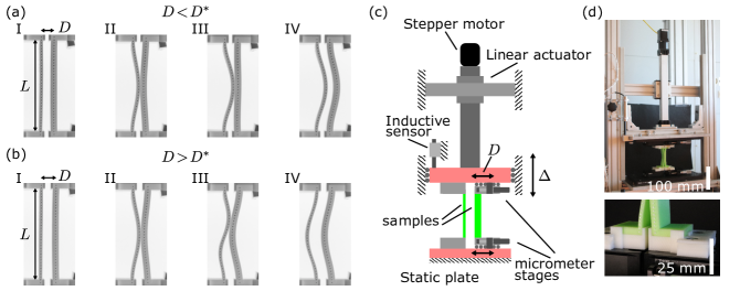
We start by discussing the qualitative nature of the evolution of two buckling beams that come in contact under increased compression (Fig. 1a,b). The beams have rectangular cross sections and equal lengths . We non-dimensionalize all other dimensions by dividing them by . The beams are compressed by a distance , leading to a strain . Their out-of-plane non-dimensional thicknesses are assumed to be large and equal, so that the buckling strains are governed by the in-plane dimensionless thicknesses and , where ; for definiteness, we assume that the thin beam is to the left of the thick beam (Fig. 1c).
In Fig. 1a,b we show the beam’s evolution under quasistatic increase of the strain . The thin beam buckles at after which the thicker beam buckles at . We assume that the beams buckle towards each other (Fig. 1aII,bII). The distance between the centrelines of the beams, , plays a crucial role, and we assume that is small enough so that the two beams eventually get into contact at some strain — for now we will assume that also. When the strain is increased further, the contact forces between the beams increase, possibly leading to complex higher order mode. This configuration becomes unstable for a critical strain . Two distinct scenario’s are then observed: either the thick beam snaps to the right (Fig. 1aIV) or the thin beam snaps to the left (Fig. 1bIV). As we will show below, the distance selects which of these two scenario’s occurs, and there is a critical distance that separates these — for , the thick beam snaps, whereas for , the thin beam snaps. Hence, post-snapping there are two distinct states where both beams are buckled, either to the right (Fig. 1bIV) or to the left (Fig. 1cIV).
We note that in this example, the thick beam snapping for remains top-down symmetric (Fig.1a), while the thin beam snapping for develops an asymmetric shape (Fig. 1b). This is consistent with the condition for the development of asymmetric beam shapes for transversely loaded buckled beams, which according to Payndey et al. should occur at and for the thin and thick beam respectively [19]. Hence, symmetric and asymmetric snapping is determined by comparing the snapping strain of the beams, , with these conditions (Fig. 2). Consistent with this, here we typically observe symmetric snapping when and asymmetric snapping when , although deviations of this can occur for . We note that the beam shape does not influence the left or right snapping of the beams, i.e., the value of .
Intuitively, the emergence of the two distinct scenario’s can be understood by considering the lateral stiffnesses of the two beams as increases. We define the lateral stiffness as the resistance of a beam to a vanishingly small point load applied at the middle of a beam perpendicular to the axis of compression. This lateral stiffness varies non-monotonically as the beam buckles: First the stiffness decreases down to zero at the buckling point, after which it increases again in the buckled configuration. By taking a small enough , approaches , so that upon contact the thick beam is barely buckled and its lateral stiffness is near zero, whereas the thin beam is deeper in the post-buckling regime and significantly stiffer. Upon further compression, the thin beam induces a snapping of the thick beam. For even smaller , becomes smaller than . Then, as the thick beam is not yet buckled when the beams make contact, the left-right symmetry of the thicker beam is broken, determining its buckling direction rightward. In contrast, for large enough , when the beams come into contact when both beams are significantly curved, the thicknesses of the beams dominate their lateral stiffness, and the thick beam induces snapping of the thin beam. While intuitive, this picture does not produce a quantitative insight into what controls , which is the focus of the remainder of this paper.
2.1 Experimental observations
To systematically explore the evolution of two post-buckled beams in contact, we designed and built a custom compression device which is stiff in all rotational and shear directions and ensures high parallelity between top and bottom plates (Fig. 1c,d). The compressive strain is applied through a linear stage, controlled by a stepper motor and monitored with an inductive probe, yielding repeatable positioning with an accuracy of under typical loads. The distance between adjacent beams is controlled by four Thorlabs XRN25 manual micrometer stages housing the fixtures which hold the beams in place with an accuracy of . We track the deformation of the beams indicated by white protrusions on the front of the beams with a grayscale CMOS camera at a resolution of , reaching a pixel density at the objective plane higher than .
We studied the evolution of pairs of beams of length and various thicknesses and . The samples studied are made out of VPS (Zhermack Elite Double 32, Young’s modulus , poisson ratio ) using molds made with FDM 3d printing on commercial UltiMaker S3 and S5 printers. After curing, the samples were allowed to rest for at least one week, well past the setting time of , to allow the material properties to settle [20, 21], after which the samples are demolded. Following this, the dimensions of the final samples were measured using an Instron universal measurement device equipped with load cell and a touch probe to measure the thickness of the relatively soft beams at various locations. The standard deviation in along the surface of the samples is . Experiments were only conducted with beams from the same batch of rubber.
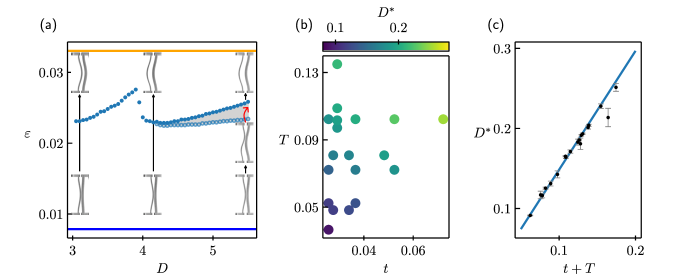
To measure , we performed multiple measurements for each beam pair at various . At the start of each measurement, each beam is manually manipulated such that its buckled state is towards the adjacent beam. We then slowly increase at a rate of until the beams snap. For a typical beam pair with and (the same pair as in Fig. 1a), as we incrementally increase between measurements, we observe that varies smoothly up until , as can be seen in (Fig. 2a). Here sharply decreases as the system both transitions from displaying the below- to above- phenomenology, as well as shifting from a symmetric snap-through mode to an asymmetric snap-through mode. We note that the transition between left and right snapping, and the transition between symmetric and asymmetric beam shapes, are independent. The transition from symmetric to asymmetric beam shapes is determined solely by the values of and — for the example here, [19], so that the thick beam remains symmetric while the thin beam takes on an asymmetric shape (Fig. 2a). Finally, we observe that as is increased above , a small strain range opens up where the asymmetric beam shape is stable, before snapping at a larger strain (Fig. 2a).
Monotonously increasing such as in Fig. 2 a, unintentionally trains the samples, such that the apparent value for differs for increasing and decreasing sweeps of . To minimize this hysteresis and accurately measure , we performed iterative measurements with a specific protocol that reduces the number of subsequent measurements above and below . We chose initial large steps of to find bounds on , and then refined the bounds with decreasing stepsizes: , , and finally . We then repeated every measurement set with exchanged left and right beams to correct for small asymmetries in the setup. We finally estimate and calculate an error through the average and RMS of the four measured bounds.
Our experiments yield for nineteen pairs of beams (Fig. 2b). We note that grows with both and , and surprisingly, the data for can be collapsed on a single axis by plotting it as a linear function: (Fig. 2c), with a least squares fit slope of . We note that this data collapse does not significantly improve by adding an empirical fit parameter , i.e. plotting as a function of . We discuss the validity and underlying physics that leads to this collapse in section 3.
2.2 Finite Element Simulations
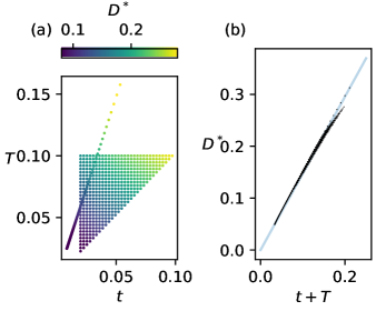
To eliminate the role of plasticity and to test the validity of our observations for a wide variety of beam parameters, we performed FEM simulations of the co-buckling beams using ABAQUS with explicit time-stepping, CPS4 elements, Neo-Hookean material properties with a Poisson ratio of 0.49, uniform element sizes and sufficient damping to prevent oscillations. To ensure the beams buckle towards each other, a small temporary load is applied before the beams buckle and removed before the beams make contact. We performed two sets of simulations. In the first set we varied both and between and , while in the second we varied the length of the beams at constant ratio . For every parameter and , we performed multiple simulations using a bisective approach to determine , until the error in was less than . The results of these simulations are shown in (Fig. 3).
Similar to our experiments, we found both symmetric and asymmetric snapping. Consistent with our experimental observations, we find that is essentially proportional to for . The fit of the numerical data yielded the slope: , which is consistent with the results of the experimental data where . We conclude that the critical distance is linear in .
3 Simplified models and theory
The phenomenology of the joint snapping of buckled beam pairs hints at the existence of a pitchfork bifurcation that occurs when the beams are in contact, i.e., before the beams snap through. Here we ask what the minimal ingredients are to observe such a pitchfork scenario. First, we investigate joint snapping for a slender beam model consisting of spherical beads connected with bars that are modeled as linear and torsional springs, as proposed by Guerra et. al. [22]. We find that for large , this simplified model captures the full phenomenology, including the existence of and both symmetric and asymmetric snapping. For decreasing values of , the model becomes more crude, but the existence and linear relation of with remains valid down to . Such beams, which we call Bellini trusses [23], clearly cannot have asymmetric shapes, again indicating that asymmetry is not essential for the understanding of the scaling of . Second, inspired by these empirical observations, we study the joint buckling and snapping of pairs of Bellini trusses in section 3.2. We show that their left or rightward snapping does not require the beams to lose contact, allowing us to focus on pairs of connected Bellini trusses. Finally, we show that the joint buckling and snapping is an example of a general scenario involving pairs of interacting elements that undergo pitchfork bifurcations at different values of the control parameter . We expand the Bellini truss system to analytically solve for and find that it is linear in (in lowest order). Together, this shows that joint snapping and the emergence of is a robust and universal phenomena.
3.1 Elastic Bead-Chains in Contact
We model the contact dynamics of post-buckled beams with a simplified model of hard beads connected by Hookean and torsional springs. For a large number of links , this model has been shown to accurately and computationally effectively model the dynamics of collections of buckled beams in contact [24, 22]. In addition, in the limit of small (), the model converges to an initially straight Bellini truss [23]. In the beam-chain model we space our nodes equidistantly along the beam length and choose the spring constants to match the stretching and bending energy of realistic beams [24]. We implement the contact dynamics between the beams with a stiff Hertzian contact model. The ends of the beams are controlled through the top and bottom particles, which control and and which enforce the ”fixed-fixed” boundary conditions of the beams (for details see SI). We implemented the model beams using damped explicit time-stepping with the Large-scale Atomic/Molecular Massively Parallel Simulator (LAMMPS) [25, 22].
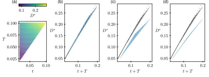
We performed simulations of pairs of beams for: , and , using the same bisective protocol to determine (Fig. 4). Here approximates the continuous limit, while corresponds to the smallest possible number of segments. For , the characteristic linear scaling emerges with , consistent with both the experimental and finite element simulation data (Fig. 4b). We note that these simulations also capture the symmetric and asymmetric beam shapes. Strikingly, for and (where the shape is purely symmetric) a comparable linear scaling of occurs ( and ) (Fig. 4(c-d)).
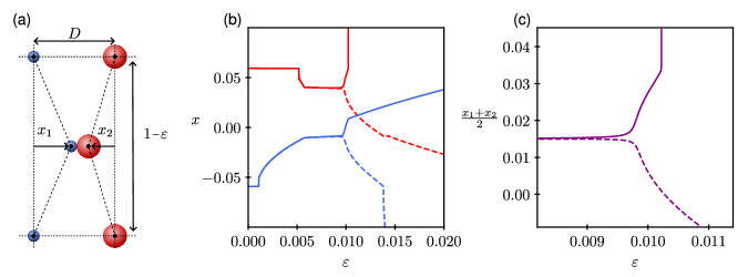
For all three cases, we note that the beams first collectively move left or right, and then snap at a higher value of . This is illustrated in Fig. 5 for the simplified case, where we compare the evolution of the lateral motion of the center nodes as function of the strain for two values of just above and below . Our data strongly suggest that the case correspond to a pitchfork bifurcation, with the evolution for given by unfolding of this pitchfork bifurcation. At larger strain, the discontinuous snapping transition occurs, but to determine , it suffices to determine the location of the pitchfork bifurcation.
3.2 Instabilities in a pair of Bellini trusses
To understand the mechanisms that govern the critical distance and its scaling with , we analytically determine the critical values of the pitchfork bifurcation in the model based on a pair of initially straight Bellini trusses. First, we connect their center nodes to model the persistent contact near the bifurcation, and separate the end nodes to capture and (See Fig. 5a). Specifically, we place the end points of the thin and thick beams at and , and require that
| (1) |
where we account for the thickness of the beams.
Second, we expand the elastic energy of both Bellini trusses up to quartic order in and linear order in , and and find at leading order (see SI):
| (2) |
where is the buckling strain with . Hence, the buckling strain scales as the ratio of the constants and which parametrizes the compressive stiffness and bending stiffness in the truss. Here, can be considered the inhibition to buckling due to the applied boundary conditions and degrees of freedom of the beam model (see SI).
Satisfying Eq. 1, we obtain the total potential energy:
| (3) |
We now obtain a closed form expression for by locating the pitchfork bifurcation in this quartic energy expansion. We first, without loss of generality, choose to eliminate the cubic terms in the expansion. Hence, and we then write the potential in the form:
| (4) |
The stable and unstable equilibria of the system are found at the roots of , where:
| (5) | ||||
| (6) |
with:
| (7) |
| (8) |
Crucially, we do not need to solve for the roots of explicitly; to find the bifurcation point, we only need to detect a change in the number of roots. The multiplicity of the roots of can be determined from the discriminant . We note that this strategy is generally applicable for polynomials of arbitrary degree, whereas finding the solutions to such polynomials is generally not possible. As increases, the system changes from monostability to bistability. For , this happens through a pitchfork bifurcation at . For this happens through a saddle node bifurcation. This change of stability corresponds to crossing , where the pitchfork bifurcation occurs for and the saddle node bifurcation occurs otherwise; in the latter case, the location of the saddle node determines whether the beams move left or right. As depends only on and not (Eq. 8), we can solve for :
| (9) |
which can be substituted into Eq. 1 to obtain :
| (10) |
In addition, we obtain the critical strain by solving at and obtain
| (11) |
We thus find that scales linearly with , consistent with our experimental and numerical results. In addition, we find a testable relation between the slope and the strain at which the beams buckle, as both depend on : , while . Thus we predict that the boundary conditions of the beams influence , e.g. pinned-pinned beams will have a smaller than fixed-fixed beams. Comparing the Bellini truss model to the simulations with (see SI), we find a predicted , which is comparable to the value obtained from simulations: .
4 Conclusion and discussion
We studied the collective snapping of two buckled beams in contact by means of experiment, numerics and theory. Using experiments and FEM simulations, we found a linear relation between the critical distance and the combined width of the two beams: . We studied a simplified model consisting of compressive rods connected by torsional springs [22]. We find that at large , this model accurately captured the collective snapping and critical distance, while at small , the model allows to identify the essential mechanism that controls the eventual direction of snapping: a pitchfork bifurcation that occurs at critical strain and distance . Furthermore, this model allows to obtain a closed form solution for and which captures the linear relation between and .
Our approach can be extended to a wide variety of scenarios where two bistable elements are strongly coupled, e.g., where the collective state can be described by a single coordinate. These include Bellini trusses that are precurved, and more generally, any buckling elements. The essential physics is that when two systems that undergo symmetric or asymmetric pitchfork bifurcations are coupled, the collective behavior is governed by a new pitchfork bifurcation.
References
- [1] A. Rafsanjani, A. Akbarzadeh, D. Pasini, Snapping Mechanical Metamaterials under Tension, Advanced Materials 27 (39) (2015) 5931–5935. doi:10.1002/adma.201502809.
- [2] K. Bertoldi, V. Vitelli, J. Christensen, M. van Hecke, Flexible mechanical metamaterials, Nature Reviews Materials 2 (11) (2017) 17066. doi:10.1038/natrevmats.2017.66.
- [3] L. A. Lubbers, M. van Hecke, C. Coulais, A nonlinear beam model to describe the postbuckling of wide neo-Hookean beams, Journal of the Mechanics and Physics of Solids 106 (2017) 191–206. doi:10.1016/j.jmps.2017.06.001.
- [4] H. Yang, L. Ma, Multi-stable mechanical metamaterials by elastic buckling instability, Journal of Materials Science 54 (4) (2019) 3509–3526. doi:10.1007/s10853-018-3065-y.
- [5] D. Yang, L. Jin, R. V. Martinez, K. Bertoldi, G. M. Whitesides, Z. Suo, Phase-transforming and switchable metamaterials, Extreme Mechanics Letters 6 (2016) 1–9. doi:10.1016/j.eml.2015.11.004.
- [6] C. Coulais, A. Sabbadini, F. Vink, M. van Hecke, Multi-step self-guided pathways for shape-changing metamaterials, Nature 561 (7724) (2018) 512–515. doi:10.1038/s41586-018-0541-0.
- [7] L. J. Kwakernaak, M. van Hecke, Counting and Sequential Information Processing in Mechanical Metamaterials, Physical Review Letters 130 (26) (2023) 268204. doi:10.1103/PhysRevLett.130.268204.
- [8] J. Ding, M. Van Hecke, Sequential snapping and pathways in a mechanical metamaterial, The Journal of Chemical Physics 156 (20) (2022) 204902. doi:10.1063/5.0087863.
- [9] R. Khajehtourian, D. M. Kochmann, Phase transformations in substrate-free dissipative multistable metamaterials, Extreme Mechanics Letters 37 (2020) 100700. doi:10.1016/j.eml.2020.100700.
- [10] P. Holmes, G. Domokos, G. Hek, Euler Buckling in a Potential Field, Journal of Nonlinear Science 10 (4) (2000) 477–505. doi:10.1007/s003320010002.
- [11] P. Holmes, G. Domokos, J. Schmitt, I. Szeberényi, Constrained Euler buckling: An interplay of computation and analysis, Computer Methods in Applied Mechanics and Engineering 170 (3-4) (1999) 175–207. doi:10.1016/S0045-7825(98)00194-7.
- [12] J.-S. Chen, S.-Y. Hung, Deformation and stability of an elastica constrained by curved surfaces, International Journal of Mechanical Sciences 82 (2014) 1–12. doi:10.1016/j.ijmecsci.2014.03.001.
- [13] S. Katz, S. Givli, The Postbuckling Behavior of Planar Elastica Constrained by a Deformable Wall, Journal of Applied Mechanics 84 (5) (2017) 051001. doi:10.1115/1.4036018.
- [14] R. S. Manning, G. B. Bulman, Stability of an elastic rod buckling into a soft wall, Proceedings of the Royal Society A: Mathematical, Physical and Engineering Sciences 461 (2060) (2005) 2423–2450. doi:10.1098/rspa.2005.1458.
- [15] J.-S. Chen, L.-C. Wang, Contact between two planar buckled beams pushed together transversely, International Journal of Solids and Structures 199 (2020) 181–189. doi:10.1016/j.ijsolstr.2020.04.029.
- [16] J.-S. Chen, Z.-H. Yang, On the asymmetric line-contact deformation between two planar elasticae, International Journal of Solids and Structures 256 (2022) 111991. doi:10.1016/j.ijsolstr.2022.111991.
- [17] Z. P. Bažant, L. Cedolin, Stability of Structures: Elastic, Inelastic, Fracture and Damage Theories, WORLD SCIENTIFIC, 2010. doi:10.1142/7828.
- [18] A. Magnusson, M. Ristinmaa, C. Ljung, Behaviour of the extensible elastica solution, International Journal of Solids and Structures 38 (46-47) (2001) 8441–8457. doi:10.1016/S0020-7683(01)00089-0.
- [19] A. Pandey, D. E. Moulton, D. Vella, D. P. Holmes, Dynamics of Snapping Beams and Jumping Poppers, EPL (Europhysics Letters) 105 (2) (2014) 24001. arXiv:1310.3703, doi:10.1209/0295-5075/105/24001.
- [20] B. Florijn, C. Coulais, M. Van Hecke, Programmable mechanical metamaterials: The role of geometry, Soft Matter 12 (42) (2016) 8736–8743. doi:10.1039/C6SM01271J.
- [21] T. Chen, M. Pauly, P. M. Reis, A reprogrammable mechanical metamaterial with stable memory, Nature 589 (7842) (2021) 386–390. doi:10.1038/s41586-020-03123-5.
- [22] A. Guerra, A. Slim, D. P. Holmes, O. Kodio, Self-Ordering of Buckling, Bending, Bumping Beams, Physical Review Letters 130 (14) (2023) 148201. arXiv:2210.11324, doi:10.1103/PhysRevLett.130.148201.
- [23] P. X. Bellini, The concept of snap-buckling illustrated by a simple model, International Journal of Non-Linear Mechanics 7 (6) (1972) 643–650. doi:10.1016/0020-7462(72)90004-2.
- [24] A. Guerra, D. P. Holmes, Emergence of structure in columns of grains and elastic loops, Soft Matter 17 (33) (2021) 7662–7669. doi:10.1039/D1SM00787D.
- [25] A. P. Thompson, H. M. Aktulga, R. Berger, D. S. Bolintineanu, W. M. Brown, P. S. Crozier, P. J. In ’T Veld, A. Kohlmeyer, S. G. Moore, T. D. Nguyen, R. Shan, M. J. Stevens, J. Tranchida, C. Trott, S. J. Plimpton, LAMMPS - a flexible simulation tool for particle-based materials modeling at the atomic, meso, and continuum scales, Computer Physics Communications 271 (2022) 108171. doi:10.1016/j.cpc.2021.108171.
Appendix A Mathematical Derivation Bellini Truss
A compressible beam can be modelled by a collection of compressive trusses serially linked by torsional springs, as shown by Guerra et.al. [24]. For small angles we can write the potential of such a beam as (Fig. 1):
| (12) |
where is the compression of each spring and the change in angle from the resting configuration. The spring constants and are chosen to match the compressive stiffness and bending stiffness of beams with a rectangular cross section, so that and .

A Bellini truss corresponds to the case. Under imposed top-down symmetry ( and ) the summation can be performed to obtain:
| (13) |
where we absorbed the summation over the number of springs into the coefficients and .
To express the potential in and , we express , to obtain:
| (14) |
Instead of attempting to minimize the full energy Eq. (14), we expand it to fourth order in and first order in around , and obtain:
| (15) |
As , , and are all small, we discard the highest order terms and , and obtain the leading order potential:
| (16) |
This potential transitions from a monostable to a bistable form when the term switches sign at . Diving by produces the rescaled potential that makes this transition explicit:
| (17) |
where the transition from a monostable to bistable potential occurs at .