Phase-stabilised self-injection-locked microcomb
2Physics Department, Universität Hamburg UHH, Luruper Chaussee 149, 22761 Hamburg, Germany
†These authors contributed equally
∗tobias.herr@desy.de )
Microresonator frequency combs (microcombs) hold potential for precision metrology in a compact form factor impacting applications such as point-of-care diagnostics, environmental monitoring, time-keeping, navigation and astronomy. Through the principle of self-injection locking, electrically-driven chip-based microcombs with low complexity are now possible. However, phase-stabilisation of such self-injection-locked microcombs, a prerequisite for metrological frequency combs, has yet to be attained. Here, addressing this critical need, we demonstrate full phase-stabilisation of a self-injection-locked microcomb. The microresonator is implemented in a silicon nitride photonic chip, and by controlling a pump laser diode and a microheater with low voltage signals (sub 1.5 V), we achieve independent actuation of the comb’s offset and line spacing frequencies. Both actuators reach a bandwidth of over 100 kHz and permit phase-locking of the microcomb to external frequency references. These results establish photonic chip-based, self-injection-locked microcombs as a low-complexity, yet versatile source for coherent precision metrology in emerging applications.
Optical frequency combs provide large sets of laser lines that are equidistant in optical frequency and mutually phase-coherent [1, 2]. Owing to this property, they have enabled some of the most precise measurements in physics and are pivotal to a vast range of emerging applications from molecular sensing to geonavigation. Frequency combs based on high-Q nonlinear optical microresonators (microcombs) [3, 4] that can be fabricated in complementary metal–oxide–semiconductor (CMOS) compatible, low-cost, scalable, wafer-scale processes [5, 6], promise to bring frequency comb technology into widespread application beyond the confines of optics laboratories [7, 8, 9].
In microcombs, nonlinear processes partially convert a continuous-wave (CW) driving laser with frequency into a series of comb lines that are mutually spaced in frequency by the comb’s repetition rate , so that , describes the frequencies in the comb ( is a mode index relative to the pump; see Fig. 1c). For many comb-based precision measurements, it is crucial to independently control the comb’s defining parameters, here and , on a level that permits full phase control, i.e. phase-locking, of and to external frequency references. This is equivalent to controlling the carrier wave and envelope of the temporal optical waveform as indicated in Fig. 1d. For instance, this is important for molecular spectroscopy, environmental monitoring, medical diagnostics, geonavigation, exoplanet searches, and other emerging applications that rely on phase-coherent links between electromagnetic waves.
A major advancement in microcombs came through the principle of self-injection locking (SIL) [10, 11, 12], which enabled electrically-driven comb sources with drastically reduced operational complexity and chip-level integration [13, 14, 15, 16, 17, 18, 19, 20]. Instead of a low-noise tabletop pump laser, SIL utilises a chip-scale semiconductor pump laser and a narrow linewidth injection feedback from a high-Q microresonator. The SIL mechanism leads to a low-noise pump laser and elegantly ensures that the laser is intrinsically tuned to the resonator for comb generation. Although highly attractive, the simplicity and compactness of SIL-based combs entail a critical drawback with regard to controlling and . In contrast to previous non-SIL systems in which the frequency and the power of a tabletop pump laser have been used as independent actuators to simultaneously phase-stabilise and [21, 22, 23], in SIL systems, these parameters are not independent (both depend on the laser pump current). Previous work has already accomplished stabilisation of one degree of freedom () [24], however, phase-stabilisation of both degrees of freedom is an outstanding challenge. This lack of full phase-stabilisation in SIL microcombs represents a serious shortcoming for metrological applications.
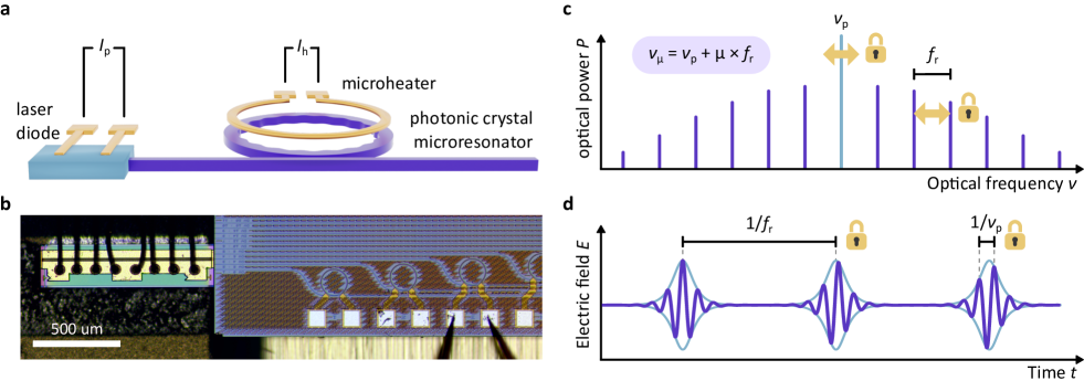
Here, we demonstrate a fully phase-stabilised self-injection-locked microcomb. The small form factor chip-scale microcomb is electrically-driven and leverages synthetic reflection to achieve reliable SIL operation [20]. In addition to the laser pump current, we utilise an integrated electric microheater [25, 26] as a second independent actuator (see Fig. 1a and b). Both actuators achieve an effective locking bandwidth of more than and permit robust phase-locking of and to external frequency references. Importantly, our system does not employ electro-optic, acousto-optic or piezo-electric actuation and relies solely on low-voltage (sub) CMOS-compatible control signals, meeting a critical requirement of chip-integrated technologies.
Setup
Fig. 2a shows the experimental setup for the stabilisation and characterisation of the SIL microcomb. This microcomb source is based on dissipative Kerr-solitons (DKS) [27, 4, 7] in a CW laser-driven chip-integrated silicon nitride photonic crystal ring resonator (PhCR) [28, 29, 30, 20]. The microresonator is characterised by a free spectral range of , anomalous group velocity dispersion, and a high quality factor (see Methods for more details). An integrated metallic microheater is embedded in the silica cladding above the resonator waveguide, for fast thermal actuation of the microresonator. Complementary to piezo-electric or electro-optic actuators [31, 32, 33], which in an integrated setting can also reach high actuation bandwidth, microheaters are attractive as they provide a robust, long-lifetime and low-voltage solution that is readily compatible with silicon-based photonic chip technology. The photonic chip is butt-coupled to a semiconductor distributed feedback (DFB) CW laser diode delivering approximately of on-chip optical pump power at . Our system leverages a recently demonstrated synthetic reflection technique [20], where the nano-patterned corrugation of the PhCR generates tailored optical feedback for robust self-injection locking of the driving laser diode, also forcing exclusive and deterministic single-soliton operation [28]. Importantly, synthetic reflection can substantially extend the range of pump frequency-to-resonance detuning accessible via SIL, resulting in an increased overlap between the SIL operation and the DKS existence ranges. This is beneficial for phase-coherent stabilisation of self-injection-locked microcombs as it extends the actuation range of the driving laser frequency while remaining in SIL operation [20].
The generated microcomb is out-coupled from the chip through a cleaved ultra-high numerical aperture optical fibre (UHNA-7) using index-matching gel to minimise unwanted back-scattering at the chip facet. Once the temperature and injection phase are appropriately adjusted (the DFB laser and microresonator dies are actively and independently temperature-stabilised), the system deterministically enters single-DKS operation when the laser diode current is set to a predetermined set point (). Fig. 2c shows the resulting microcomb spectrum, with a full-width-at-half-maximum (FWHM) of and a total chip output power of (including pump).

In SIL DKS operation, the DFB laser’s emission frequency (the central comb line of the microcomb) can be tuned by adjusting the current around the set point with a sensitivity of , which also affects the DKS repetition rate by . A second degree of freedom is provided by the resonator’s microheater, which we operate at a current bias of (). Via the microheater, the microcomb’s repetition rate can be tuned with a sensitivity of . As the laser diode and the microresonator are coupled through SIL, the microheater also induces a shift in the microcomb’s centre frequency (pump line) with a sensitivity of . The actuator sensitivities are summarised in Table 1. As the corresponding control matrix is diagonalisable with non-zero diagonal elements, the two actuators enable independent control of both degrees of freedom of the SIL microcomb ( and ).
| Sensitivity | ||
|---|---|---|
Depending on the application scenario, a frequency comb may be stabilised to different references, such as two lasers for frequency division and clock operation [34, 35], or a repetition rate and self-referencing signal [36, 37, 22, 38, 39, 40] to provide a phase-coherent radio-frequency-to-optical link. Here, for the purpose of validating the capability of our system to achieve full-phase stabilisation, we perform an independent out-of-loop experiment, where we test the agreement between the microcomb and a conventional optical frequency comb (OFC). The repetition rate of the conventional OFC is phase-locked to a signal from a GPS disciplined Rb-clock [41]. As Fig. 2b illustrates, an error signal for stabilisation of is generated by recording the offset beatnote between the microcomb line and the closest line of the reference OFC [21, 36] (note that this offset is not to be confused with the carrier-envelope offset frequency). To obtain a repetition rate error signal, we utilise electro-optic phase-modulation (modulation frequency ) of the central comb line and detect the beating between 17 modulation sideband and the first sideband of the microcomb [42]. Both beat notes are then frequency-divided down to approximately , and the error signals are extracted through phase detection with respect to the Rb-clock signal (all microwave sources and recording devices are also referenced to the signal from the Rb-clock). The phase-locked loops (PLLs) are implemented using two proportional-integral-derivative (PID) controllers, acting onto laser diode driving current and the microheater current for the offset and repetition rate stabilisation, respectively. As follows from Table 1, alternative configurations of the PLLs are possible, e.g. switching the actuators or simultaneously using both actuators for both degrees of freedom to diagonalise the control matrix.

Finally, the out-of-loop validation of the microcomb’s phase-stability is performed by recording the beat note between the second sideband of the microcomb and the sideband of the reference OFC. Impacted by both phase locks, the out-of-loop measurement is a key metric in evaluating the overall system performance.
Experiments
The successive initiation of both PLLs is shown in Fig. 3a where the spectrogram of the out-of-loop beat note is presented. While activating the offset lock already substantially enhances the stability of the out-of-loop beat note (at in Fig. 3a), fluctuations of the microcomb’s repetition rate are only suppressed with the additional activation of the repetition rate lock (at in Fig. 3a), resulting in a fully phase-stabilised system. Thus, the two high-bandwidth actuators and the extended detuning range, reliably obtained through synthetic reflection, enable robust phase-stabilisation of the microcomb.
Next, we study the long-term stability of our source in the fully phase-locked state by recording the frequency of the out-of-loop beat note with a gate time and without dead time between the non-overlapping samples (the frequency is extracted from the signal’s quadratures, see Methods). The measured frequency (shifted to zero) is displayed in Fig. 3b and the corresponding histogram is presented in Fig. 3c (standard deviation of ). We also acquire analogous data for the offset and repetition rate in-loop beat note signals with the microcomb fully phase-locked. All three datasets are processed to extract the overlapping Allan deviation (OAD) presented in Fig. 3d (see Methods). As expected for a phase lock, both the OADs of the in-loop and out-of-loop signals average down over time. The scaling of the OAD is and for and while that of the out-of-loop signal scales with . The expected small deviation from the ideal scaling results from technical/environmental noise (e.g. lab air conditioning). The phase noise of the out-of-loop beat note in the free-running, offset-locked, and fully-locked states is shown in Fig. 3e. In the fully locked state, at frequencies below , the out-of-loop phase noise measurement is limited by the digital PLL stabilising the reference oscillator [41].

The closed-loop frequency responses of the repetition rate and offset PLLs are shown in Fig. 4a and b respectively (with the respective other degree of freedom unlocked). Bandwidths of over and , respectively, are achieved for the microheater-based repetition rate actuator and the laser diode-based offset actuator. Both actuators allow for broadband noise suppression, as can be observed from the phase noise of the repetition rate and offset signals (Fig. 4c and d) and their corresponding beat notes (Fig. 4e and f). We compute the residual phase modulation (PM) on and in the fully-locked state (obtained by integrating the phase noise down to ), yielding a root mean square (RMS) residual PM of and respectively. The residual PM values are much smaller than , indicating a robust phase lock, and no substantial degradation of the locking performance is observed when both degrees of freedom are locked simultaneously.
Conclusion
In conclusion, we demonstrate full phase-stabilisation of a self-injection-locked microresonator frequency comb. Our system is based on a photonic-chip integrated microresonator and relies solely on CMOS-compatible driving and control voltages. The control actuators, laser diode and microheater, achieve over in feedback bandwidth. In conjugation with synthetic reflection, they enable robust phase locking of the microcomb to external frequency references in an unprecedentedly compact form factor. Our microcomb source (without electronics; Fig. 1b) is implemented in a sub- footprint and does not require tabletop lasers, amplifiers, or high-voltage actuators. Future work could pursue additional self-referencing [36, 37, 22, 38, 39, 40] to implement a phase-coherent radio-frequency to optical link. The demonstrated source is highly relevant to emerging applications, including those in portable, mobile and integrated settings, and may also inform the design of other chip-integrated light sources, such as low-noise, rapidly tunable lasers or optical parametric oscillators.
Methods
Sample fabrication.
The samples were fabricated commercially by LIGENTEC SA using ultraviolet stepper optical lithography. The microresonator ring radius of corresponds to a free-spectral range (FSR) of , while a waveguide width of and a waveguide height of provide anomalous group-velocity dispersion (difference between neighbouring FSRs at the pump frequency, ). Synthetic feedback to the driving DFB diode laser is provided by a nano-patterned corrugation, the amplitude and period of which were chosen to achieve a forward-backwards coupling rate at the pump wavelength of [20]. All modes, including the pump mode, exhibit a high quality factor of .
Frequency stability measurements.
To measure the long-term stability of the microwave signals, we record the beat note’s in-phase and quadrature (I/Q) components using the built-in I/Q-analyser of an electronic spectrum analyser (Rohde & Schwarz FSW26). The phase is then extracted from the I/Q data, from which the overlapping Allan deviation is computed using the AllanTools python module implementing the NIST standards [43]. Frequency counts are obtained by evaluating the finite differences of the extracted phase over the gate time. Spectrograms, spectra, and phase noises are calculated similarly from IQ data.
Author Contributions
T.W., A.U., and T.H. conceived the experiment. T.W. and A.U. designed the setup and the photonic chip, performed the experiments, and analysed the data. T.V. developed and operated the reference comb. B.R. supported the design of the resonator and the experiments. T.H. supervised the work. T.W., A.U., and T.H. prepared the manuscript with input from all authors.
Funding
This project has received funding from the European Research Council (ERC) under the EU’s Horizon 2020 research and innovation program (grant agreement No 853564), from the EU’s Horizon 2020 research and innovation program (grant agreement No 965124) and through the Helmholtz Young Investigators Group VH-NG-1404; the work was supported through the Maxwell computational resources operated at DESY.
Disclosures
All authors declare no conflict of interest.
References
- [1] Tara Fortier and Esther Baumann “20 Years of Developments in Optical Frequency Comb Technology and Applications” In Communications Physics 2.1 Nature Publishing Group, 2019, pp. 1–16 DOI: 10.1038/s42005-019-0249-y
- [2] Scott A. Diddams, Kerry Vahala and Thomas Udem “Optical Frequency Combs: Coherently Uniting the Electromagnetic Spectrum” In Science 369.6501 American Association for the Advancement of Science, 2020, pp. eaay3676 DOI: 10.1126/science.aay3676
- [3] P. Del’Haye et al. “Optical Frequency Comb Generation from a Monolithic Microresonator” In Nature 450.7173, 2007, pp. 1214–1217 DOI: 10.1038/nature06401
- [4] T. Herr et al. “Temporal Solitons in Optical Microresonators” In Nature Photonics 8.2, 2014, pp. 145–152 DOI: 10.1038/nphoton.2013.343
- [5] Jacob S. Levy et al. “CMOS-compatible Multiple-Wavelength Oscillator for on-Chip Optical Interconnects” In Nature Photonics 4.1 Nature Publishing Group, 2010, pp. 37–40 DOI: 10.1038/nphoton.2009.259
- [6] V. Brasch et al. “Photonic Chip–Based Optical Frequency Comb Using Soliton Cherenkov Radiation” In Science 351.6271, 2016, pp. 357–360 DOI: 10.1126/science.aad4811
- [7] Tobias J. Kippenberg, Alexander L. Gaeta, Michal Lipson and Michael L. Gorodetsky “Dissipative Kerr solitons in optical microresonators” In Science 361.6402, 2018, pp. eaan8083 DOI: 10.1126/science.aan8083
- [8] Alexander L. Gaeta, Michal Lipson and Tobias J. Kippenberg “Photonic-Chip-Based Frequency Combs” In Nature Photonics 13.3 Nature Publishing Group, 2019, pp. 158–169 DOI: 10.1038/s41566-019-0358-x
- [9] Alessia Pasquazi et al. “Micro-Combs: A Novel Generation of Optical Sources” In Physics Reports 729, Micro-Combs: A Novel Generation of Optical Sources, 2018, pp. 1–81 DOI: 10.1016/j.physrep.2017.08.004
- [10] V.. Vasil’ev et al. “High-Coherence Diode Laser with Optical Feedback via a Microcavity with ’whispering Gallery’ Modes” In Quantum Electronics 26.8, 1996, pp. 657 DOI: 10.1070/QE1996v026n08ABEH000747
- [11] W. Liang et al. “Whispering-Gallery-Mode-Resonator-Based Ultranarrow Linewidth External-Cavity Semiconductor Laser” In Optics Letters 35.16 Optica Publishing Group, 2010, pp. 2822–2824 DOI: 10.1364/OL.35.002822
- [12] Nikita M. Kondratiev et al. “Recent Advances in Laser Self-Injection Locking to High-Q Microresonators” In Frontiers of Physics 18.2, 2023, pp. 21305 DOI: 10.1007/s11467-022-1245-3
- [13] W. Liang et al. “High Spectral Purity Kerr Frequency Comb Radio Frequency Photonic Oscillator” In Nature Communications 6.1, 2015, pp. 7957 DOI: 10.1038/ncomms8957
- [14] N.. Pavlov et al. “Narrow-Linewidth Lasing and Soliton Kerr Microcombs with Ordinary Laser Diodes” In Nature Photonics 12.11 Nature Publishing Group, 2018, pp. 694–698 DOI: 10.1038/s41566-018-0277-2
- [15] Brian Stern et al. “Battery-Operated Integrated Frequency Comb Generator” In Nature 562.7727, 2018, pp. 401 DOI: 10.1038/s41586-018-0598-9
- [16] Arslan S. Raja et al. “Electrically Pumped Photonic Integrated Soliton Microcomb” In Nature Communications 10.1, 2019, pp. 680 DOI: 10.1038/s41467-019-08498-2
- [17] Boqiang Shen et al. “Integrated Turnkey Soliton Microcombs” In Nature 582.7812 Springer US, 2020, pp. 365–369 DOI: 10.1038/s41586-020-2358-x
- [18] Chao Xiang et al. “High-Performance Lasers for Fully Integrated Silicon Nitride Photonics” In Nature Communications 12.1 Nature Publishing Group, 2021, pp. 6650 DOI: 10.1038/s41467-021-26804-9
- [19] Andrey S. Voloshin et al. “Dynamics of Soliton Self-Injection Locking in Optical Microresonators” In Nature Communications 12.1 Nature Publishing Group, 2021, pp. 235 DOI: 10.1038/s41467-020-20196-y
- [20] Alexander E. Ulanov et al. “Synthetic Reflection Self-Injection-Locked Microcombs” In Nature Photonics Nature Publishing Group, 2024, pp. 1–6 DOI: 10.1038/s41566-023-01367-x
- [21] P. Del’Haye et al. “Full Stabilization of a Microresonator-Based Optical Frequency Comb” In Physical Review Letters 101.5 American Physical Society, 2008, pp. 053903 DOI: 10.1103/PhysRevLett.101.053903
- [22] Pascal Del’Haye et al. “Phase-Coherent Microwave-to-Optical Link with a Self-Referenced Microcomb” In Nature Photonics 10.8 Nature Publishing Group, 2016, pp. 516–520 DOI: 10.1038/nphoton.2016.105
- [23] Travis C. Briles et al. “Interlocking Kerr-microresonator Frequency Combs for Microwave to Optical Synthesis” In Optics Letters 43.12, 2018, pp. 2933 DOI: 10.1364/OL.43.002933
- [24] Qing-Xin Ji et al. “Engineered Zero-Dispersion Microcombs Using CMOS-ready Photonics” In Optica 10.2 Optica Publishing Group, 2023, pp. 279–285 DOI: 10.1364/OPTICA.478710
- [25] Xiaoxiao Xue et al. “Mode-Locked Dark Pulse Kerr Combs in Normal-Dispersion Microresonators” In Nature Photonics 9.9 Nature Publishing Group, 2015, pp. 594–600 DOI: 10.1038/nphoton.2015.137
- [26] Chaitanya Joshi et al. “Thermally Controlled Comb Generation and Soliton Modelocking in Microresonators” In Optics Letters 41.11 Optica Publishing Group, 2016, pp. 2565–2568 DOI: 10.1364/OL.41.002565
- [27] François Leo et al. “Temporal Cavity Solitons in One-Dimensional Kerr Media as Bits in an All-Optical Buffer” In Nature Photonics 4.7, 2010, pp. 471–476 DOI: 10.1038/nphoton.2010.120
- [28] Su-Peng Yu et al. “Spontaneous Pulse Formation in Edgeless Photonic Crystal Resonators” In Nature Photonics 15.6 Nature Publishing Group, 2021, pp. 461–467 DOI: 10.1038/s41566-021-00800-3
- [29] Erwan Lucas et al. “Tailoring Microcombs with Inverse-Designed, Meta-Dispersion Microresonators” In Nature Photonics 17.11 Nature Publishing Group, 2023, pp. 943–950 DOI: 10.1038/s41566-023-01252-7
- [30] Grégory Moille et al. “Fourier Synthesis Dispersion Engineering of Photonic Crystal Microrings for Broadband Frequency Combs” In Communications Physics 6.1 Nature Publishing Group, 2023, pp. 1–11 DOI: 10.1038/s42005-023-01253-6
- [31] Scott B. Papp, Pascal Del’Haye and Scott A. Diddams “Mechanical Control of a Microrod-Resonator Optical Frequency Comb” In Physical Review X 3.3 American Physical Society, 2013, pp. 031003 DOI: 10.1103/PhysRevX.3.031003
- [32] Junqiu Liu et al. “Monolithic Piezoelectric Control of Soliton Microcombs” In Nature 583.7816 Nature Publishing Group, 2020, pp. 385–390 DOI: 10.1038/s41586-020-2465-8
- [33] Yang He et al. “High-Speed Tunable Microwave-Rate Soliton Microcomb” In Nature Communications 14.1 Nature Publishing Group, 2023, pp. 3467 DOI: 10.1038/s41467-023-39229-3
- [34] Scott B. Papp et al. “Microresonator Frequency Comb Optical Clock” In Optica 1.1 Optical Society of America, 2014, pp. 10–14 DOI: 10.1364/OPTICA.1.000010
- [35] Jiang Li et al. “Electro-Optical Frequency Division and Stable Microwave Synthesis” In Science 345.6194 American Association for the Advancement of Science, 2014, pp. 309–313 DOI: 10.1126/science.1252909
- [36] J.. Jost et al. “Counting the Cycles of Light Using a Self-Referenced Optical Microresonator” In Optica 2.8 Optica Publishing Group, 2015, pp. 706–711 DOI: 10.1364/OPTICA.2.000706
- [37] J.. Jost et al. “All-Optical Stabilization of a Soliton Frequency Comb in a Crystalline Microresonator” In Optics Letters 40.20 Optica Publishing Group, 2015, pp. 4723–4726 DOI: 10.1364/OL.40.004723
- [38] Victor Brasch et al. “Self-Referenced Photonic Chip Soliton Kerr Frequency Comb” In Light: Science & Applications 6.1 Nature Publishing Group, 2017, pp. e16202–e16202 DOI: 10.1038/lsa.2016.202
- [39] Kaiyi Wu et al. “Vernier Microcombs for High-Frequency Carrier Envelope Offset and Repetition Rate Detection” In Optica 10.5 Optica Publishing Group, 2023, pp. 626–633 DOI: 10.1364/OPTICA.486755
- [40] Grégory Moille et al. “Kerr-Induced Synchronization of a Cavity Soliton to an Optical Reference” In Nature 624.7991 Nature Publishing Group, 2023, pp. 267–274 DOI: 10.1038/s41586-023-06730-0
- [41] T. Voumard et al. “1-GHz Dual-Comb Spectrometer with High Mutual Coherence for Fast and Broadband Measurements” In Optics Letters 47.6 Optica Publishing Group, 2022, pp. 1379–1382 DOI: 10.1364/OL.448575
- [42] Pascal Del’Haye, Scott B. Papp and Scott A. Diddams “Hybrid Electro-Optically Modulated Microcombs” In Physical Review Letters 109.26, 2012, pp. 263901 DOI: 10.1103/PhysRevLett.109.263901
- [43] William Riley and David Howe “Handbook of Frequency Stability Analysis” Special Publication (NIST SP), National Institute of StandardsTechnology, Gaithersburg, MD, 2008 URL: https://tsapps.nist.gov/publication/get_pdf.cfm?pub_id=50505