Performance Evaluation of a Full-Duplex
UWA System in Lake Experiments
Abstract
In this work we present a full-duplex (FD) underwater acoustic (UWA) communication system simultaneously transmitting and receiving acoustic signals in the same frequency bandwidth. To simplify the FD hardware, the system exploits a recently designed transducer capable of simultaneously transmitting and receiving signals. The key challenge of implementing an FD system is to cancel at the near-end receiver the strong self-interference (SI) from the near-end transmitter. By using advanced adaptive filtering algorithms providing high accuracy channel estimates, a high level of SI cancellation can be achieved when the far-end signal is absent. However, the SI channel estimation performance is limited in FD scenarios since the far-end signal acts as an interference when estimating the near-end SI channel. In this paper, we propose an FD UWA communication system which alternates between the SI cancellation and far-end data demodulation. An adaptive Rake combiner with multipath interference cancellation is implemented to improve the demodulation performance in time-varying multipath channels. The performance of the FD UWA system is evaluated in lake experiments. It is shown that the proposed adaptive Rake combiner with multipath interference cancellation significantly outperforms the conventional Rake combiner in all the experiments. The experimental results demonstrate that, with the new Rake combiner, the detection performance of the proposed FD UWA system is comparable with that of the half-duplex system.
Index Terms:
Adaptive filter, Channel estimation, Full-duplex, Rake combiner, Self-interference cancellation, Underwater acoustics.I Introduction
Underwater acoustic (UWA) communication suffers from limited frequency bandwidth for data transmission [1]. To increase the spectral efficiency within the available bandwidth, we consider the full-duplex (FD) operation, which allows a simultaneous transmission and reception of acoustic signals in the same frequency bandwidth [2, 3, 4, 5]. Apart from the far-end signal, the near-end receiver also receives a strong self-interference (SI) signal from the near-end transmitter. Therefore, a high level of SI cancellation (SIC) is required to detect the weak desired signal arriving from the far-end transmitter.
In FD UWA systems, the spatial-domain SIC can be used for the SI suppression. In [6], a spatial SIC scheme is proposed, which uses a phased array of transducers and acoustic vector sensors. The SIC is achieved by adjusting the beampattern of the phased array based on the direction of arrivals estimated by the acoustic vector sensors. Sea experimental results demonstrate a spatial SIC of 40 to 60 dB depending on the steering angle of the near-end transducer. In [7], an FD UWA system with a combination of spatial SIC and digital SIC is proposed and investigated in an anechoic pool; this system requires the knowledge of the direction of the far-end transmitter, which is not always available in practice. UWA communication systems with antenna arrays are difficult for practical implementation. However, even without using an antenna array, in an FD system, typically the transmitting and receiving transducers are two separate devices. In [8], we proposed an FD transducer that can be used for simultaneous transmission and reception of acoustic signals. We use this transducer in our UWA FD experiments.
For FD terrestrial radio communications, a combination of analogue and digital cancellation is normally used. Analogue cancellation is applied before digital cancellation to avoid the analogue-to-digital converter (ADC) saturation [2, 3, 4]. In FD UWA systems, compared to terrestrial radio systems, low-frequency signals are transmitted. In such a case, high resolution ADCs up to 24 bits can be used, which makes it feasible to achieve a high level of cancellation in the digital domain alone. Therefore, digital cancellation is considered as the main SIC approach in FD UWA systems [9, 10, 11, 12]. In this work, we implement and investigate the performance of an FD UWA system with digital cancellation.
Two factors limiting the digital SIC performance in FD UWA systems are nonlinearities introduced by the equipment [9, 13, 14] and fast variation of the SI channel [11, 12]. The dominant source of the nonlinearities is the power amplifier (PA). It is found that the SIC performance can be significantly improved by using the PA output as the reference signal (regressor) for SI channel estimation compared to the case of using the original digital data [15, 13]. After addressing the nonlinearities caused by the PA, a high level of digital SIC can be achieved in time-invariant scenarios with a classical recursive least-squares (RLS) adaptive filter [16]. In practice, the SI channel can be fast time-varying, e.g., due to reflections from the moving sea surface [17]. To achieve a high level of digital SIC in time-varying scenarios, advanced adaptive filtering algorithms with good tracking performance have been recently proposed [11, 12, 18, 19]. The SIC performance provided by these adaptive algorithms has been evaluated in shallow lake experiments. However, in those experiments, the far-end transmission is not considered and the SIC performance is only limited by the ambient noise level.
With the FD operation, the received signal includes the near-end SI, background noise, and also the far-end signal. When estimating the near-end SI channel, the far-end signal acts as an additional interference (noise), which reduces the overall SI to noise ratio. To achieve a high level of SIC, the influence of the far-end signal, in addition to the ambient noise, on the SIC performance must be taken into account.
To avoid the impact of the far-end signal on the near-end SI channel estimation performance, a scheme is proposed in [9] with estimation of the near-end SI channel before the far-end signal arrives. An over-parametrization based RLS algorithm with a sparsity constraint is proposed for the SI channel estimation and evaluated in a water tank with a static multipath channel. This approach works well in time-invariant scenarios. However, the SI channel needs to be frequently re-estimated to ensure a good tracking performance in fast time-varying scenarios. In such a case, it is difficult to guarantee sufficiently long time intervals for the SI channel estimation, non-overlapping with the far-end transmission.
To reduce the impact of the far-end signal on the SIC performance, we propose an FD UWA system which alternates the near-end SIC and far-end data demodulation in turbo iterations. The proposed system does not require a non-overlapping period between the near-end and far-end transmissions. In the first iteration, the SI channel is estimated, treating the far-end signal as an extra noise. At the receiver, the residual signal after SIC is used for tentative far-end data demodulation. In the second iteration, the far-end signal is reconstructed using the far-end data and channel estimates and then removed from the received signal. After that, a similar procedure is performed as in the first iteration. As the estimation performance for both the near-end SI channel and far-end channel is significantly improved in the second iteration, a better demodulation performance can be achieved. Further iterations can be useful to improve the communication performance.
In [20], the conventional Rake combiner [21] is used for demodulation of far-end data in multipath channels. The Rake combiner provides the maximal ratio combining for signal components propagated over various channel paths. However, such a receiver ignores the multipath interference, i.e., the interference from one multipath signal component to another, which significantly degrades the receiver performance. In [22], a receiver with linear equalization, multipath interference reconstruction and interference cancellation is proposed. Simulation results indicate that the receiver performance is significantly improved due to the multipath interference cancellation. In [23], a Rake-IC combiner with multipath interference cancellation is implemented in a UWA modem with half-duplex data packet transmission. This Rake-IC combiner shows good demodulation performance in static/slow time-varying scenarios. In this paper, we propose an adaptive version of the Rake-IC combiner, which is capable of providing good demodulation performance in FD time-varying scenarios.
To evaluate the performance of the FD UWA system, both half-duplex and FD communication experiments are conducted using recently developed FD transducers [8] in lake experiments. The proposed Rake-IC combiner outperforms the conventional Rake combiner in all the experiments. Furthermore, results indicate that the proposed FD system with the Rake-IC combiner can provide the demodulation performance close to that of the half-duplex system. The contributions of this paper are as follow.
-
•
An FD UWA system with multiple iterations is proposed for cancellation of the interference from the far-end transmission when estimating the SI channel and cancellation of the SI when demodulating the far-end data.
-
•
An adaptive version of the Rake-IC combiner is proposed to improve the detection performance in time-varying multipath channels. Its performance is investigated in the lake experiments.
-
•
The performance of the proposed FD UWA system is investigated and compared with that of the half-duplex system in lake experiments.
II System model
The block diagram of the FD UWA system is shown in Fig. 1.
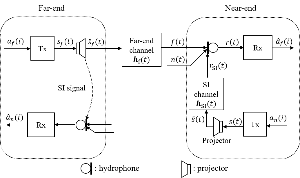
As shown in Fig. 1, the signal at the near-end receiver is given by:
| (1) | ||||
where denotes the convolution, is the SI, is the signal emitted by the near-end projector, represents the SI channel impulse response, is the far-end signal, is the signal emitted by the far-end projector, represents the far-end channel impulse response and is the background noise. The near-end and far-end channel responses, and , and the far-end signal are unknown at the receiver and should be estimated.
In subsection II-A, description of signals used for near-end and far-end transmission is given. In subsection II-B, the receiver structure is introduced.
II-A Transmitted signals
The structure of the near-end transmitter is shown in Fig. 2.
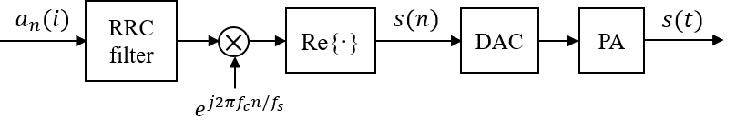
For the near-end transmission, a pseudo-random sequence of Binary Phase Shift Keying (BPSK) data symbols is used. The data symbols are up-sampled and pulse-shaped by a root-raised cosine (RRC) filter. The RRC filter output is then up-converted to the carrier frequency . Afterwards, the signal is digital-to-analogue converted, amplified by a PA, and the near-end PA output is transmitted by a transducer.
For the far-end transmission, Quadrature Phase Shift Keying (QPSK) symbols consisting of superimposed binary pilot and data symbols [24, 25] are used:
| (2) |
where is a binary pseudo-random pilot sequence and is the information data symbols obtained by encoding transmitted data using a convolutional code and interleaving the encoded symbols. The far-end symbols go through the same modulation process as shown in Fig. 2.
II-B Receiver structure
The receiver performs two tasks, the first task is the near-end SIC, and the second task is the far-end data demodulation.

The passband received signal is first analogue-to-digital converted by an ADC to produce the passband samples , which then go through the complex demodulation process to produce the baseband samples as shown in Fig. 3, where an RRC filter is used for the low-pass filtering.
The general structure of the receiver is shown in Fig. 4.
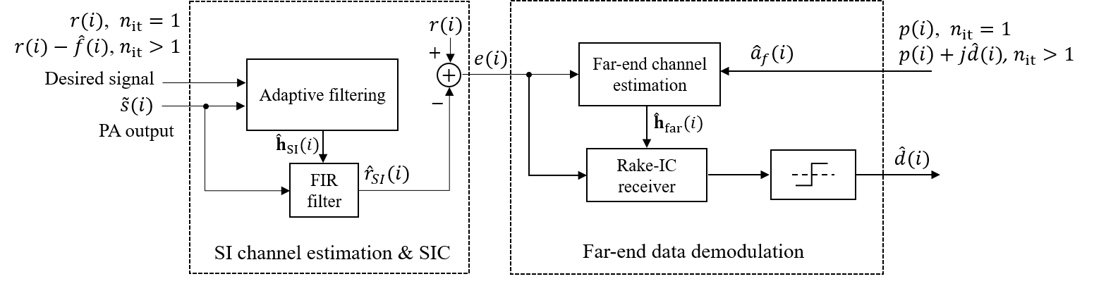
In the first iteration (), since the far-end signal estimate is not available yet, the received signal is the desired signal of an adaptive filter used for the SI channel estimation and near-end SIC. To prevent the PA nonlinearity affecting the SI channel estimation, the baseband digitalized PA output is used as the regressor in the adaptive filter, instead of utilising the symbols [13]. The baseband signal is obtained through the same complex demodulation process as shown in Fig. 3.
The baseband PA output is fed to a finite impulse response (FIR) filter whose impulse response is a delayed copy [11, 12] of the impulse response of the adaptive filter, i.e., the SI channel estimate . For performing the SIC, the FIR filter output is subtracted from the received signal . The residual signal is an estimate of the far-end signal (plus noise) which is used for the far-end channel estimation and far-end data demodulation.


The far-end channel estimate is obtained by another adaptive filter. An estimate of the far-end data , obtained at the previous iteration, and the residual signal are used as the regressor and the desired signal of the adaptive filter, respectively. In the first iteration (), there is no estimate of the far-end data , but the pilot symbols are known and therefore we use . In further iterations (), there is a tentative estimate of the far-end data, and therefore we use an improved estimate .
In this paper, two types of Rake combiner are considered for the far-end data demodulation, the conventional Rake combiner and Rake-IC combiner with multipath interference cancellation; they will be described in Section III. The imaginary part of the Rake combiner output is interleaved and decoded using the Viterbi decoder [21]. The decoded message is encoded and interleaved in the same way as it is done in the transmitter and thus obtained sequence of symbols is used as an estimate of the far-end symbols .
With and now available, an estimate of the far-end signal is reconstructed by filtering in a FIR filter with the impulse response ; this estimate will be used in the next iteration.
III Rake combiner with interference cancellation
The conventional Rake combiner shown in Fig. 5(a) is implemented as an FIR filter with its th filter coefficient at the th time instant given by:
| (3) |
where is a far-end channel estimate at the th time instant (a vector of size with channel tap estimates) and is the length of the far-end channel impulse response. The conventional Rake combiner performs the maximal-ratio combining but it ignores the multipath interference, while the Rake-IC combiner performs the multipath interference cancellation before the maximal-ratio combining.
In this section, we introduce an adaptive version of the Rake-IC combiner proposed in [23], which is implemented assuming that the multipath channel is static. The adaptive Rake-IC combiner can deal with time-varying multipath interference cancellation. The block diagram of the proposed Rake-IC combiner is shown in Fig. 5(b).
In each branch in Fig. 5(b), only one multipath signal component is kept for processing. The other multipath components are removed from the residual signal based on the far-end channel estimate . This process can either be individually performed for each branch, or it can be performed in a more computationally-efficient way as shown in Fig. 5(b). First, all of the signal components are removed from , then every signal component is added to the difference individually on each branch with a corresponding delay. In such a case, we obtain the th multipath signal free from the multipath interference. Then, the maximal-ratio combining results in the signal
| (4) |
Fig. 5(b) shows a general version of the proposed combiner with all multipath components participating in the maximal ratio combining.
In Section IV, we show that the demodulation performance can be significantly improved when using the proposed Rake combiner instead of the conventional Rake combiner.
IV Lake experiments
In this section, we investigate the performance of the FD UWA system in two experimental sites. For comparison, half-duplex (HD) experiments were also conducted, i.e., experiments with the far-end transmission only.
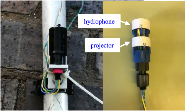
The lake experiments were conducted using the recently developed two-sensor FD transducer (see Fig. 6) which contains two piezo-ceramic cylinders, one of them is used as a projector and the other one is used as a hydrophone [8].
For both the near-end and far-end transmission, the transmitted signal is sampled at kHz. The RRC filter with a roll-off factor of is used for pulse-shaping and low-pass filtering. In every experiment, signals of 60 s length are transmitted. A silence period of 5 s is added at the beginning of the transmitted signal to measure the background noise. Far-end data are encoded with convolutional codes of different code rates as detailed in Table I.
| Code Rate | Constraint Length | Polynomials in Octal |
|---|---|---|
| 1/4 | 8 | [235 275 313 357] |
| 1/3 | 8 | [225 331 367] |
| 1/2 | 6 | [53 75] |
| 2/3 | [5 4] | [23 35 0; 0 5 13] |
IV-A Experimental site 1
IV-A1 Experimental setup
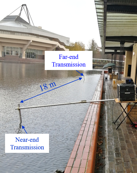
The first experimental site is the shallow lake at the University of York. The maximum depth of the experimental site is around 1 m. The experimental setup is shown in Fig. 7. Both transducers were placed at approximately 0.5 m depth and the distance between them was around 18 m.
Both near-end and far-end signals are transmitted at kHz carrier frequency with kHz bandwidth. The far-end SNR was around dB. For the FD experiment, the received SI to noise ratio was around dB, i.e., the far-end signal level at the receiver was about -51 dB with respect to the SI level.
IV-A2 SI and far-end channel estimation
The SI channel estimation is significantly more demanding than the far-end channel estimation, since the level of the required SI cancellation is much higher than that of the far-end signal cancellation. The SI and far-end channels in this experiment were fast-varying due to the transducers positioned close to the lake surface. Therefore, for the SI channel estimation, we use the homotopy SRLS-L-DCD (HSRLS-L-DCD) adaptive filter [12]. This adaptive filter uses the basis function expansion of the channel variations to improve its tracking performance and exploits the channel sparsity to improve the estimation accuracy. For the far-end channel estimation, the delayed sliding-window RLS (SRLSd) adaptive filter [11] is used. The HSRLS-L-DCD algorithm could also be used for the far-end channel estimation, but the SRLSd algorithm is less complicated.
The HSRLS-L-DCD adaptive filter length is taps, which corresponds to a delay spread of ms (the baseband sampling rate is = 4 kHz). The sliding window length in the first iteration is set to and, in further iterations, . A high value of allows better performance in noisy environment, which is the case in the first iteration when the interference from the far-end signal has not been cancelled yet. A smaller allows better tracking of the channel variations in less noisy environment, which is the case in the second and further iterations after cancelling the far-end interference. The adaptive filter uses the parabolic approximation of the time variations of the complex multipath amplitudes [12].
The SRLSd adaptive filter length is taps (5 ms) and the sliding window length is in the first iteration and in the second and further iterations. The reasons for changing in the first and further iterations are similar to that for the HSRLS-L-DCD adaptive filter.
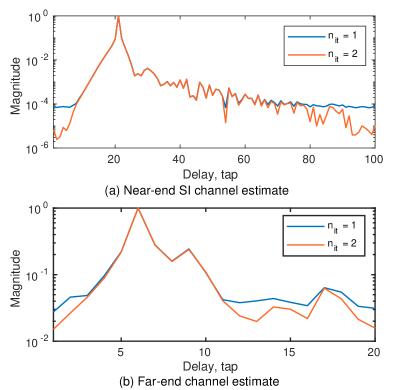
An example of the magnitude of the near-end and far-end channel impulse responses at the first and second iterations are shown in Fig. 8. In Fig. 8a, it can be seen that the multipath structure of the SI channel estimate is much clearer after the second iteration. The same is true for the far-end channel estimate shown in Fig. 8b. This demonstrates that both the SI and far-end channel estimation performance are improved at the second iteration.
IV-A3 Demodulation performance
To obtain the demodulation performance at various far-end SNRs, complex-valued Gaussian random noise with variance is added to the baseband received signal in the HD and FD experiments, where is computed as: , and and are the average power of the baseband received signal and background noise, respectively, in the HD experiment.
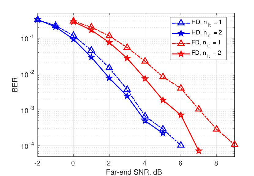
We first consider results of experiments with a rate 1/4 convolutional code, presented in Fig. 9. The BER performance of the conventional Rake combiner in HD and FD lake experiments is shown in Fig. 9(a). The demodulation performance is improved in the second iteration for both HD and FD experiments, with a performance gap of about 2 dB between these two transmission modes. In further iterations, the performance (not shown here) is the same.
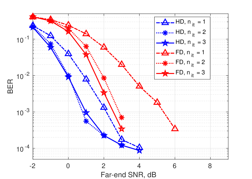
The BER performance of the Rake-IC combiner in HD and FD experiments is shown in Fig. 9(b). Fig. 9(b) further demonstrates that using multiple iterations in the receiver is beneficial for the demodulation performance. In this case, the third iteration brings some extra improvement in the performance, and the performance gap between the FD and HD modes is somewhat smaller than 2 dB.
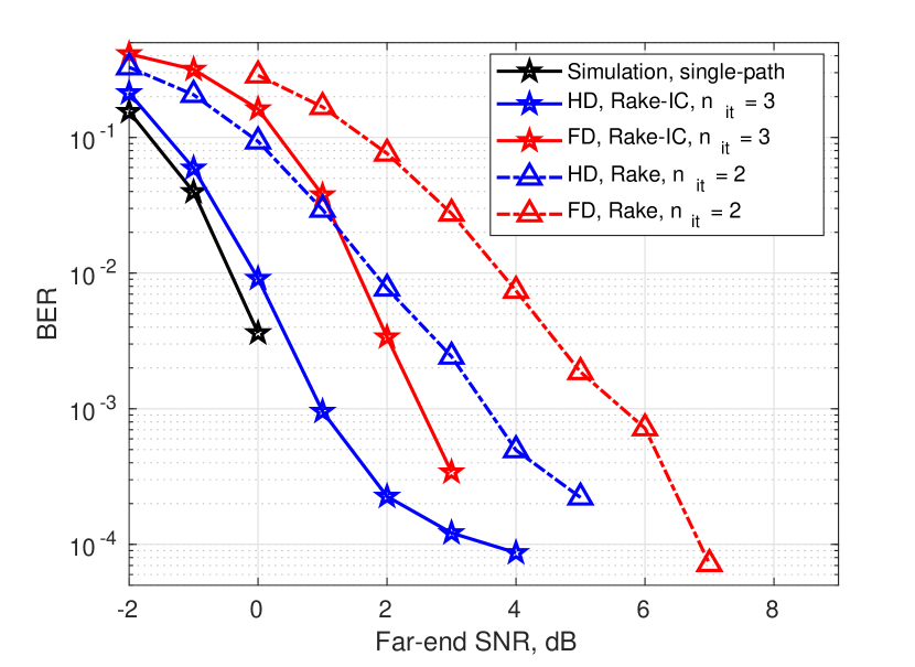
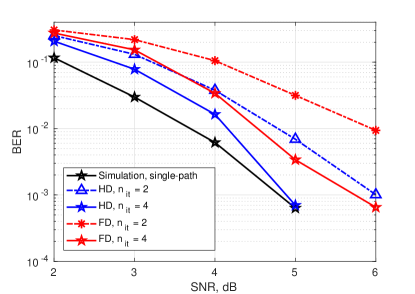
For better comparison of the Rake combiners, Fig. 9(c) shows several BER curves selected from Fig. 9(a) and Fig. 9(b). Here, we also show the BER performance obtained with the same signals via numerical simulation for the single-path static HD channel; this is a benchmark indicating the best performance that can be achieved in the ideal conditions. It can be seen that the Rake-IC combiner outperforms the conventional Rake combiner by 2-3 dB, with higher improvement at lower BERs. With the Rake-IC combiner, the BER performance in the HD experiment approaches the single-path benchmark after two iterations. This shows that the Rake-IC combiner has achieved almost ideal (maximal-ratio) combining of the multipath components with complete cancellation of the multipath interference.
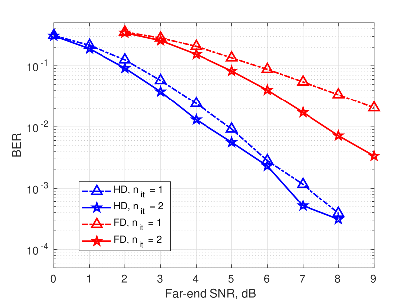
The demodulation performance of the Rake combiners with a rate 1/3 convolutional code are shown in Fig. 10. The BER curves in Fig. 10(a) and Fig. 10(b) further demonstrate the improvement in the demodulation performance achieved with turbo iterations; the performance improvement is especially high in the FD experiments. Selected BER curves for the Rake combiners in HD and FD experiments are shown in Fig. 10(c). By comparing Fig. 9(c) and Fig. 10(c), it can be seen that the SNR loss of the conventional Rake combiner to the single-path benchmark has significantly increased with the higher code rate. On the other hand, the performance of the Rake-IC combiner remains equally good for rate-1/3 and rate-1/4 convolutional codes. At a BER of , for the Rake-IC combiner, the SNR loss in the FD experiment is still about 2 dB compared to the HD experiment.
IV-B Experimental site 2
IV-B1 Experimental setup
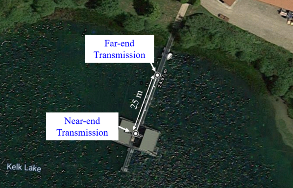
Experiments were conducted in the Kelk lake in East Yorkshire. The experimental setup is shown in Fig. 11. During the experiment, the near-end transducer was placed at 4 m depth and the far-end transducer was placed at approximately 1 m depth. The maximum depth of the site is around 7 m. The distance between the transducers was around 25 m.
Both the near-end and far-end signals of 60 s length are transmitted at kHz carrier frequency with kHz bandwidth. The far-end SNR was around dB. For the FD experiment, the SI signal to noise ratio was around dB.
IV-B2 SI and far-end channel estimation
In this scenario, the time-variation of the SI channel is not significant, therefore the SRLSd adaptive filter is capable of providing good near-end SI estimation performance in all turbo iterations; therefore, the SRLSd algorithm is used for estimation of both the SI and far-end channels. For the SI channel estimation, the filter parameters are: taps, which corresponds to a delay spread of ms (at the baseband sampling rate = 1 kHz), the sliding window length in the first iteration is and, in the further iterations, . In this scenario, the delay spread of the far-end channel is much longer (about 30 ms) compared to that in the first lake experiment (5 ms). For the far-end channel estimation, the filter parameters are: the filter length taps (30 ms) and the sliding window length in the first iteration is and, in the further iterations, .
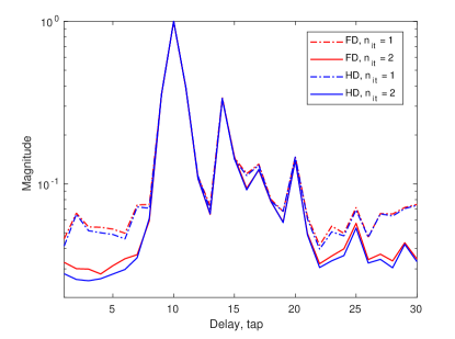
Fig. 12 shows the far-end channel estimates in the HD and FD experiments. The channel impulse responses are normalized with respect to the tap with the highest magnitude and plotted in log scale. Results are obtained for rate 1/3 convolutional code when the far-end SNR is about 3 dB. It can be seen that the accuracy of the channel estimates is significantly improved at the second iteration in both the HD and FD experiments. Another conclusion is that the SI signal is cancelled quite well in the FD experiment as the channel estimates obtained in HD and FD experiments are very similar.
IV-B3 Demodulation performance
Complex-valued Gaussian random noise with variance is added to the baseband received signal in the HD and FD experiments as described in subsection IV-A to obtain the demodulation performance at various far-end SNRs.
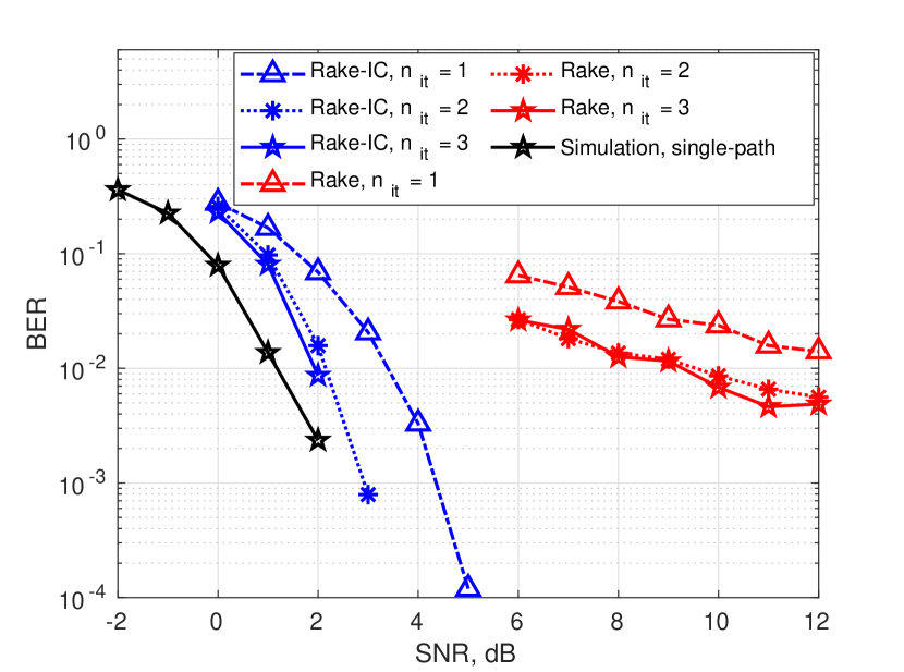
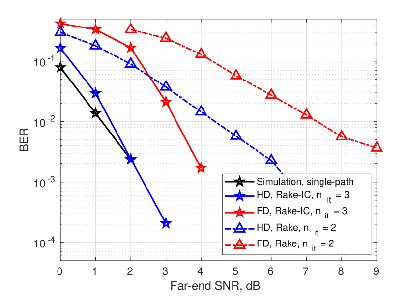
The demodulation performance of the two Rake combiners in HD experiments with rate-1/3 convolutional code are shown in Fig. 13(a). It can be seen that the performance of the Rake-IC combiner is very close to the single-path benchmark; the difference is within 1 dB. Even with single iteration, the SNR loss compared to the benchmark is only about 2 dB. On the other hand, in this scenario, the performance of the conventional Rake combiner significantly degrades due to the multipath interference in the far-end channel. An SNR loss of about 10 dB can be observed when comparing with the Rake-IC combiner.
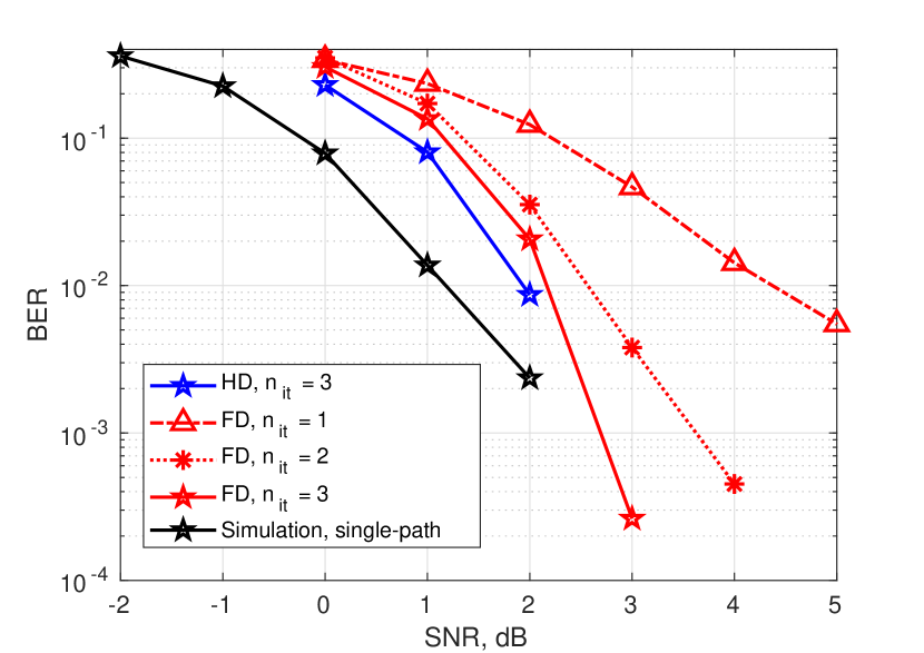
As the performance of the conventional Rake combiner is already limited in the HD experiments, only the Rake-IC combiner is considered in the FD experiments. The demodulation performance of the Rake-IC combiner with rate-1/3 convolutional code is shown in Fig. 13(b). It can be seen that the SNR loss in the FD transmission mode compared to the HD mode is less than 0.5 dB.
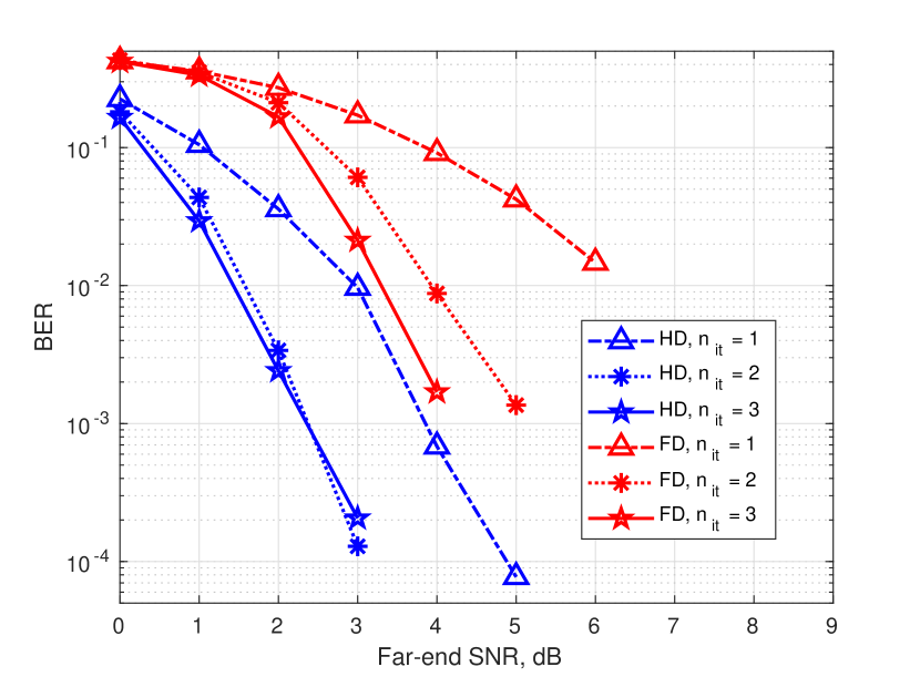
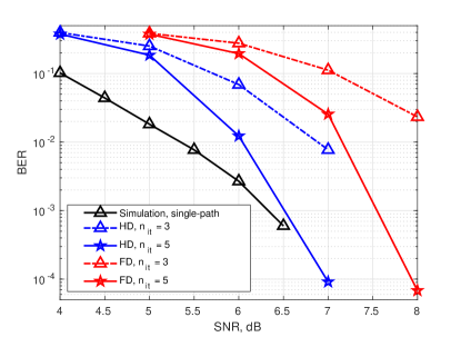
We then investigate the demodulation performance of the Rake-IC combiner with rate-1/2 convolutional code. As the code rate increases, more iterations are required to achieve the best BER performance. As can be seen in Fig. 14, the performance in the HD experiment approaches the single-path benchmark in four iterations. In the FD experiments, the performance is still comparable with that in the HD experiments and with the single-path HD benchmark; the loss to the benchmark is about 1 dB at low BERs.
Finally, the demodulation performance of the Rake-IC combiner with rate-2/3 convolutional code is shown in Fig 15. Now, five iterations are required to approach the single-path benchmark in the HD experiments. The performance gap between the FD and HD transmission, after five iterations, is about 1 dB at low BERs.
V Conclusions
In this paper, an FD UWA communication system with turbo iterations and the adaptive Rake-IC combiner has been proposed. By performing the near-end SIC and far-end data demodulation in an iterative way, the influence of the far-end signal on the SIC performance has been reduced. The use of the adaptive Rake-IC combiner improves the demodulation performance in time-varying multipath channels compared to the conventional Rake combiner. The performance of the FD UWA system has been investigated and compared with the HD counterpart in lake experiments with different code rates. As demonstrated by the experimental results, the proposed FD UWA system with the Rake-IC combiner achieves good demodulation performance in all the experiments.
References
- [1] M. Stojanovic and J. Preisig, “Underwater acoustic communication channels: Propagation models and statistical characterization,” IEEE Communications Magazine, vol. 47, no. 1, pp. 84–89, 2009.
- [2] J. I. Choi, M. Jain, K. Srinivasan, P. Levis, and S. Katti, “Achieving single channel, full duplex wireless communication,” in the 16th Annual International Conference on Mobile Computing and Networking, Chicago, Illinois, USA, 2010, pp. 1–12.
- [3] M. Duarte and A. Sabharwal, “Full-duplex wireless communications using off-the-shelf radios: Feasibility and first results,” in the 44th Asilomar Conference on Signals, Systems and Computers, Pacific Grove, California, USA, 2010, pp. 1558–1562.
- [4] M. Jain, J. I. Choi, T. Kim, D. Bharadia, S. Seth, K. Srinivasan, P. Levis, S. Katti, and P. Sinha, “Practical, real-time, full duplex wireless,” in the 17th Annual International Conference on Mobile Computing and Networking, Las Vegas, Nevada, USA, 2011, pp. 301–312.
- [5] M. Duarte, C. Dick, and A. Sabharwal, “Experiment-driven characterization of full-duplex wireless systems,” IEEE Transactions on Wireless Communications, vol. 11, no. 12, pp. 4296–4307, 2012.
- [6] Y.-T. Hsieh, Z. Qi, and D. Pompili, “Full-duplex underwater acoustic communications via self-interference cancellation in space,” Journal of Communications and Networks, 2023.
- [7] Y. Lu, X. Qing, C. Yang, Y. Zhao, S. Wu, and G. Qiao, “Spatial-digital joint self-interference cancellation method for in-band full-duplex underwater acoustic communication,” Frontiers in Marine Science, vol. 9, p. 1015836, 2022.
- [8] B. Henson, L. Shen, and Y. Zakharov, “Full-duplex UAC receiver with two-sensor transducer,” IEEE Transactions on Circuits and Systems II: Express Briefs, vol. 69, no. 12, pp. 4764–4768, 2022.
- [9] G. Qiao, S. Gan, S. Liu, L. Ma, and Z. Sun, “Digital self-interference cancellation for asynchronous in-band full-duplex underwater acoustic communication,” Sensors, vol. 18, no. 6, pp. 1700–1716, 2018.
- [10] G. Qiao, S. Gan, S. Liu, and Q. Song, “Self-interference channel estimation algorithm based on maximum-likelihood estimator in in-band full-duplex underwater acoustic communication system,” IEEE Access, vol. 6, pp. 62 324–62 334, 2018.
- [11] L. Shen, Y. Zakharov, B. Henson, N. Morozs, and P. D. Mitchell, “Adaptive filtering for full-duplex UWA systems with time-varying self-interference channel,” IEEE Access, vol. 8, pp. 187 590–187 604, 2020.
- [12] L. Shen, Y. Zakharov, L. Shi, and B. Henson, “BEM adaptive filtering for SI cancellation in full-duplex underwater acoustic systems,” Signal Processing, vol. 191, pp. 108 366–108 378, 2022.
- [13] L. Shen, B. Henson, Y. Zakharov, and P. Mitchell, “Digital self-interference cancellation for full-duplex underwater acoustic systems,” IEEE Transactions on Circuits and Systems II: Express Briefs, vol. 67, no. 1, pp. 192–196, 2019.
- [14] L. Shen, B. Henson, Y. Zakharov, and P. D. Mitchell, “Adaptive nonlinear equalizer for full-duplex underwater acoustic systems,” IEEE Access, vol. 8, pp. 108 169–108 178, 2020.
- [15] S. Li and R. D. Murch, “Full-duplex wireless communication using transmitter output based echo cancellation,” in IEEE Global Telecommunications Conference-GLOBECOM, Houston, Texas, USA, 2011, pp. 1–5.
- [16] S. Haykin, Adaptive Filter Theory. Prentice Hall, 2002.
- [17] L. Li, A. Song, L. J. Cimini, X.-G. Xia, and C.-C. Shen, “Interference cancellation in in-band full-duplex underwater acoustic systems,” in OCEANS 2015-MTS/IEEE, Washington, DC, 2015, pp. 1–6.
- [18] M. Niedźwiecki, A. Gańcza, L. Shen, and Y. V. Zakharov, “Adaptive identification of sparse underwater acoustic channels with a mix of static and time-varying parameters,” Signal Processing, vol. 200, p. 108664, 2022.
- [19] M. Niedźwiecki, A. Gańcza, L. Shen, and Y. Zakharov, “On bidirectional preestimates and their application to identification of fast time-varying systems,” in IEEE Int. Conf. Acoustics, Speech and Signal Processing (ICASSP), 2023, pp. 1–5.
- [20] L. Shen, B. Henson, and Y. Zakharov, “Full-duplex UWA communication system with two iterations,” in the 6th Underwater Communications and Networking Conference (UComms), Lerici, Italy, 2022, pp. 1–5.
- [21] J. Proakis and M. Salehi, Digital Communications. McGraw-Hill, 2008.
- [22] L. Fathi, G. Jourdain, and M. Arndt, “Hybrid linear equalizer/interference canceller receiver for advanced categories of HSDPA user equipment,” in VDE European Wireless Conference - Enabling Technologies for Wireless Multimedia Communications, 2006, pp. 1–7.
- [23] L. Shen, B. Henson, N. Morozs, Y. Zakharov, and P. D. Mitchell, “Rake receiver with interference cancellation for an underwater acoustic modem,” in Proceedings of the Underwater Acoustics Conference and Exhibition (UACE’23), Kalamata, Greece, 2023, pp. 513–520.
- [24] E. Alameda-Hernandez, D. C. McLernon, M. Ghogho, A. Orozco-Lugo, and M. Lara, “Synchronisation for superimposed training based channel estimation,” Electronics Letters, vol. 41, no. 9, pp. 565–567, 2005.
- [25] Y. V. Zakharov and A. K. Morozov, “OFDM transmission without guard interval in fast-varying underwater acoustic channels,” IEEE Journal of Oceanic Engineering, vol. 40, no. 1, pp. 144–158, 2014.