Rúa de Xoaquín Díaz de Rábago, s/n, 15782 Santiago de Compostela, Spainbbinstitutetext: Instituto de Física Corpuscular (IFIC), CSIC & Universitat de València,
Calle Catedrático José Beltrán, 2, 46980 Paterna, Valencia, Spainccinstitutetext: CINTECX, Universidade de Vigo, DSN, 36310 Vigo, Spainddinstitutetext: Department of Physics, Harvard University, 17 Oxford St, Cambridge, MA 02138, USA
On the determination of the interaction time of GeV neutrinos in large argon gas TPCs
Abstract
Next-generation megawatt-scale neutrino beams open the way to studying neutrino-nucleus scattering resorting, for the first time, to gaseous targets. This could lead to deeper knowledge of neutrino cross sections in the energy region between hundreds of MeV and a few GeV, of interest for the upcoming generation of long-baseline neutrino oscillation experiments. The challenge is, therefore, to accurately track and (especially) time the particles produced in neutrino interactions in large and seamless volumes down to few-MeV energies. We propose to accomplish this through an optically-read time projection chamber (TPC) filled with high-pressure argon and equipped with both tracking and timing functions. In this work, we present a detailed study of the time-tagging capabilities of such a device, based on end-to-end optical simulations that include the effect of photon propagation, photosensor response, dark-count rate and pulse reconstruction. We show that the neutrino interaction time could be reconstructed from the primary-scintillation signal with a precision in the range 1–2.5 ns () for point-like deposits with energies down to 5 MeV, and well below 1 ns for minimum-ionizing particle tracks. A discussion on previous limitations towards such a detection technology, and how they can be realistically overcome in the near future thanks to recent developments in the field, is presented (particularly the strong scintillation yields recently reported for Ar/CF4 mixtures). The performance presented in our analysis seems to be well within reach of next-generation neutrino-oscillation experiments through the instrumentation of the proposed TPC with conventional reflective materials and a SiPM carpet behind a transparent cathode.
1 Introduction
The time projection chamber (TPC) has been at the forefront of particle physics research for the last four decades, finding numerous applications in areas ranging from heavy-ion physics to rare-event searches Nygren:1974nfi ; Hilke:2010zz ; Nygren:2018sjx . In neutrino physics, the liquid argon TPC (LArTPC), originally proposed in the late 1970s Rubbia:1977zz , is now the cornerstone detector technology of the short- Acciarri:2015bmn and long- DUNE:2020lwj baseline neutrino oscillation programs under development in the United States. More recently, gaseous argon TPCs (GArTPCs) have also been proposed as neutrino detectors Andreopoulos:2284748 ; DUNE:2022yni . Their combination of high-resolution tracking, low detection thresholds and powerful particle identification would help improve our knowledge of neutrino-nucleus scattering in the few-GeV region, reducing systematic errors in the new generation of neutrino oscillation experiments.
A key aspect of the design of a GArTPC is that, in contrast to the liquid phase, high-resolution tracking in pure argon gas is not viable due to (i) high electron diffusion, and (ii) low primary ionization per mm combined with a very low avalanche amplification factor (around – Cantini:2014xza ; Tesi:2023 ; Olano:2023 ). Illustratively, at 10 bar and for a typical drift field of 400 V/cm, the ionization spread resulting from a 5 m drift would be cm Pack:1992 .111The subscripts T and L stand, respectively, for the charge spread transverse (perpendicular) or longitudinal (colinear) to the drift field. Such diffusion values are more than one order of magnitude higher than those usually found in state-of-the-art gaseous TPCs, while the gain is at least times lower (see, e.g., ref. Alme:2010ke ). Electron diffusion can be greatly reduced through the addition of a small fraction of a molecular gas NEXT:2018qyk (typically, at the few-percent level or above). This helps as well with the stabilization of the avalanche process Gonzalez-Diaz:2017gxo by either absorbing the very energetic scintillation photons emitted by rare gases or quenching its emission Takahashi:1983 .
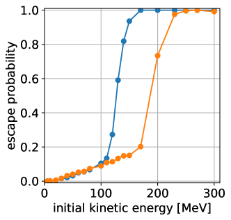
The above creates an apparent technological dilemma: in a GArTPC, good tracking capabilities and usable levels of scintillation seem to be incompatible. In the LArTPCs used as neutrino detectors, the primary-scintillation signal provides the absolute timing of the recorded tracks, which is required to disambiguate their position along the drift direction. In a GArTPC, although one could in principle rely on external instrumentation to time those neutrino interactions through tracks escaping the TPC, that would leave unreconstructed the 3D position of many reactions of interest. Even in the gaseous phase, tracks of up to 100–200 MeV may range-out inside the TPC depending on the conditions (see figure 1). In other words, the main advantage of a GArTPC, its ability to reconstruct low-energy interactions, would be hindered by its inability to time-tag them.
An appealing path forward is to induce wavelength shifting of the argon scintillation directly in the gas, as this process can simultaneously remove the avalanche-destabilizing vacuum-ultraviolet (VUV) photons from argon, while preserving a significant fraction of the scintillation yield. One can anticipate additional advantages like easier light collection and detection away from the VUV, or a faster time response (given the very long time constant of 3.2 µs from the Ar triplet state Amsler:2007gs , responsible for about 80–90% of the argon scintillation emission Santorelli:2020fxn ). If gaseous wavelength-shifting can be accomplished through a molecular species, then the suppression of diffusion to manageable levels as well as the enhancement of the avalanche multiplication factor can be expected too.
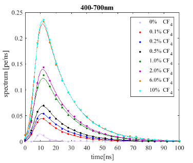
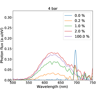
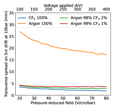
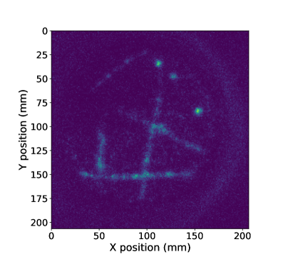
Recently, high wavelength-shifting efficiency has been demonstrated for Ar/CF4 mixtures Amedo:2023far ; AmedoYields:2023 , resulting, for a mere 1% volume fraction of CF4, in scintillation strengths of about 1400 photons per MeV in the range between 400 and 700 nm (figure 2, top row). Such small additive concentrations are an important asset in order to avoid the contamination of the neutrino-Ar scattering data with spurious interactions from other nuclear species. Simulations performed with Pyboltz AlAtoum:2019zpy support the fact that, at 400 V/cm, the strong electron cooling of CF4 would reduce diffusion down to mm for a drift length of 5 m (fig. 2, bottom-left panel), a value lower even than what can be achieved with standard gas mixtures such as Ar/CH4 at 90/10 (P10), for which mm is expected. According to Pyboltz, this performance is preserved in a wide range of drift fields (tens of V/cm/bar in a pressure-reduced representation). Although information on avalanche gain for low-quenched Ar/CF4 mixtures is scarce, values in excess of have been reported in single-wire configuration Deptuch:2007ef , and around in 3-GEM stacks down to CF4 concentrations as low as 2% at around atmospheric pressure DGD:2016 . The latter detector, instrumenting an area of cm2, provided high-quality Brunbauer:2018xzt ; Brunbauer:2018ebn and X-ray Brunbauer:2018nyz images with reliable performance over the course of years, and is still in use at CERN’s Gas Detectors Development laboratory. More recently, muon tracks have been imaged in Ar/CF4 (99/1) at 1 bar by resorting to a double glass-THGEM stack Amedo:2023pmh , (fig. 2 bottom-right panel). The characteristics of CF4 as a wavelength-shifting gas are convenient: it is relatively fast (most of the light is emitted with a time constant of about 15 ns Margato:2013gqa , a feature preserved in the presence of Ar) and its emission spectrum lies largely in the near ultraviolet and visible regions, offering good prospects for detection. It is also highly immune to contaminants: at 1 bar, even a (certainly unrealistic) 3% N2 contamination would cause a tolerable reduction of the CF4 scintillation strength Margato:2012 .
Here, we assess the potential of Ar/CF4 mixtures for time-tagging in GArTPCs. The paper is structured as follows: section 2 describes the detector concept and discusses which photosensor seems the fittest for our purposes given today’s technological landscape; in section 3 we present the Geant4 simulation we have developed to simulate light collection in the GArTPC and discuss the main results for energy threshold, time and energy resolution for various event topologies; section 4 contains a technical discussion on (i) the impact of the photosensor response, digitization scheme and electrical noise, (ii) the performance with Winston cones and, finally, (iii) a simple proposal of an active cryostat aimed at achieving photosensor cooling in high-pressure closed systems, together with first experimental results validating the idea; finally, in section 5 we present a summary of the main results.
2 Detector concept
We will consider a cylindrical TPC with a diameter of 5 m and a length of 5 m, filled with Ar/CF4 (99/1) at a pressure of 10 bar and a temperature of about 293 K, corresponding to a mass of argon of about 1.5 tons. Anode and cathode planes at the ends of the cylinder define a single-drift region. While the dimensions of such a chamber are comparable to those of the ALICE TPC Alme:2010ke ; Lippmann:2014lay , its active mass would exceed that of any existing or past gaseous TPC by at least one order of magnitude. The chosen geometry is inspired in the high-pressure TPC proposal of the DUNE experiment DUNE:2022yni , that arguably sets the standard for future TPCs to be used as active targets in neutrino physics.
Regarding the readout of the primary ionization, we will assume hole-based amplification as in gas electron multipliers (GEMs Sauli:1997qp ; Sauli:2016eeu or THGEMs Bressler:2023wrl ). The choice arises from the fact that, in the proposed concept, it is important to maximize the amount of primary scintillation while screening the one stemming from the avalanche process. Unlike open amplification structures (such as those based on wires Alme:2010ke ), modern hole-based micropattern gas detectors (MPGDs) can accomplish this to a large extent. For instance, quintuple Blatnik:2015bka or dissimilar-pitch Lippmann:2014lay GEM stacks are known to suppress feedback levels with minimal degradation in performance, while aluminium-electrode GEMs Chernyshova:2019 may be used to enhance the collection of primary scintillation from the main TPC volume. Even as other solutions might be developed along the way, we stick in this work to demonstrated concepts.
Regarding the readout of the primary scintillation, we will assume, for simplicity, that photon detection occurs behind a highly transparent cathode plane. Covering the field cage with photosensors is, in principle, possible nEXO:2018ylp , despite additional technical difficulties: charging-up and electric field distortions, need of high voltage insulation and temperature stabilization, complexity of bringing services and reading out signals, and cost. For a tracking TPC in which most of the tracks would exit, precisely, through the field-cage, there is no existing implementation that backs this idea. Therefore, we opted at this point for evaluating a more conventional solution where the field cage is lined with reflective materials (see, e.g., NEXT:2020pbx ; NEXT:2022cmg and references therein).
There are, in principle, several large-area photosensors that could be suitable for the task proposed, including photomultiplier tubes (PMTs), microchannel plates (MCPs), avalanche photodiodes (APDs), CMOS or CCD cameras, and silicon photomultipliers (SiPMs). Examination of the main technical caveats seem to favour one of these options, as long as the discussion is restricted to demonstrated technological solutions:
-
•
PMTs: when it comes to large aperture, there is currently no commercial PMT above 1 inch that is rated for 10 bar Hamamatsu . Moreover, ensuring magnetic-field compatibility inside the intended 0.5 T field would require dedicated R&D. Last, the quantum efficiency (QE) of vacuum photocathodes in the red region of the spectrum is largely below what is achievable with silicon devices, and sits generally below 10%.
-
•
MCPs: compared to PMTs, microchannel plates have better immunity to magnetic fields, but they suffer too from the lack of availability of high pressure devices and low QE in the visible range, as PMTs do. For both PMTs and MCPs, detection of the UV-component of Ar/CF4 might offer a better alternative in case of vacuum photocathodes, but remains to be studied.
-
•
APDs: as shown in section 3, in the present concept the scintillation will be generally down to single-photon levels per sensor, thus making this option non viable.
-
•
CMOS or CCD cameras: with a QE as high as 70% or more in the visible spectrum and coupled to suitable optics, they can image large areas; however, they cannot be realistically used for the small signals expected in our case (hundreds of photoelectrons over the entire readout plane) due to simple solid-angle considerations.
-
•
SiPMs: they can operate under high pressure and high magnetic fields, and their quantum efficiency can reach 30% at 600 nm. Historically, SiPMs have suffered from high dark count rate (DCR); however, improvements over the last decade brought it down to the level of 50–100 at room temperature NepomukOtte:2016ktf ; HamamatsuMPPC:2023 , with ongoing efforts to bring it even further down ECFA:2021 . SiPMs are typically small, and hence not optimal for large-area coverage unless several channels can be combined. Their large gain facilitates this process, and signal-to-noise ratios better than 10 have been achieved, for instance, ganging together twenty-four mm2 SiPMs DIncecco:2017bau .
In summary, an array of SiPMs tiling the cathode could, realistically, instrument the proposed TPC as long as the photosensors’ DCR can be kept at tolerable levels. A common solution involves operation at low temperature, as the DCR is reduced by about an order of magnitude every 25 \celsius NepomukOtte:2016ktf ; HamamatsuMPPC:2023 :
| (1) |
As will be shown in section 3, temperatures around seem sufficient, in our case, for achieving the target performance. These moderately-low local temperatures are not unknown to particle physics instrumentation, even with the rest of the detector operating comfortably at room temperature (e.g., PANDA:2008rpr ). Ongoing studies point to the fact that two PMMA windows — one at the cathode and another one next to the photosensors — would suffice at providing thermal insulation between the active volume of the TPC and the SiPM plane, keeping the cooling power at reasonable levels (see section 4). For the evaluation of the detector performance, we consider as a prospective SiPM the 14160/14161 series by Hamamatsu, with a photosensor arrangement in square tiles of 35 35 cm2 at a pitch of 40 cm, leading to a maximum fill factor of . The additional 5 cm provides space for the frames of the cryostat assembly, greatly reducing the thermal stress on the PMMA window. Conservatively, the reference simulations presented here have been done for half of the maximum fill factor estimated this way (i.e., , 7.5 m2 photosensor area).
3 Detector performance
3.1 Simulation
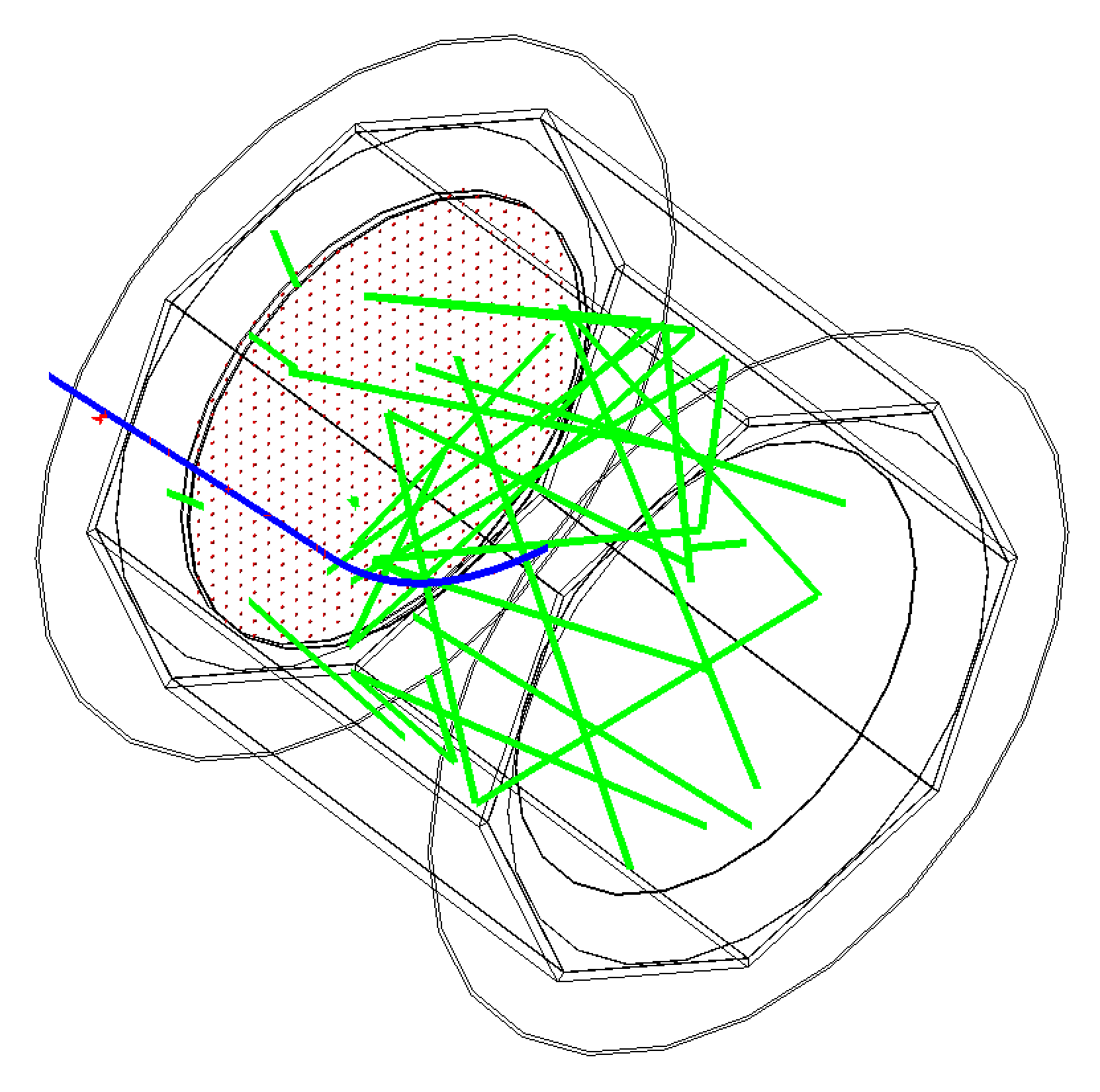
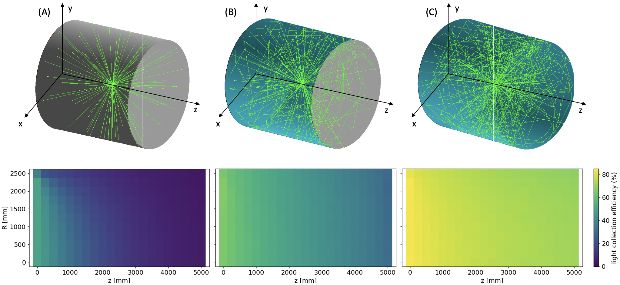
We evaluated the expected performance of the TPC concept described above by means of a Geant4 Allison:2016lfl ; Allison:2006ve ; GEANT4:2002zbu end-to-end simulation that covers from the generation and transport of particles interacting in the detector, through to the production of the primary scintillation photons (and ionization electrons), and, finally, their tracing (collection), amplification and conversion into electric signals. It implements a detailed optical model of the TPC geometry (see figure 3), for which we will consider three main configurations (see figure 4, top row): (A) no reflectors; (B) a PTFE-lined field cage (with exposed field shapers, to minimize charging-up) and a fully-absorbing anode; (C) a PTFE-lined field cage and an anode based on aluminized GEMs.
The primary scintillation spectrum of Ar/CF4 mixtures Amedo:2023far follows closely the one of pure CF4 Morozov:2010 , with three main emissions: two in the UV range (230 nm and 280 nm), attributed to CF transitions, and one in the visible range (630 nm), attributed to a CF transition. Given the better prospects of the visible emission for the detection of low-energy/highly-ionizing radiation Amedo:2023far , only this latter component will be considered in the following. The scintillation time profile for Ar/CF4 gas (at 99/1, 10 bar) was taken from the same work (fig. 2, top-left panel). The effective reflectivity of the PTFE-covered drift wall, which assumes aluminium field spacers as inserts in a 20:1 ratio (95 fill factor), is 94.5%. This effective value results from the weighted reflectivity of the PTFE, Janecek:2012 ; NEXT:2020pbx , and of the aluminium, Lindseth:1999ole , in the wavelength range of 550–700 nm. The effective reflectivity of the GEM-based anode depends on the ratio of the hole diameter to the hole pitch. Taking the large-pitch GEMs from the ALICE TPC Lippmann:2014lay as a reference (70 µm hole diameter, 280 µm pitch), the effective GEM reflectivity in case of aluminium electrodes may be up to . For more conventional GEMs (70 µm hole diameter, 140 µm pitch), the resulting reflectivity is .
3.2 Light collection efficiency
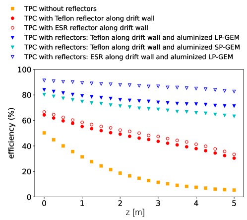
Using our Geant4 simulation, we computed the light collection efficiency () of the detector, defined as the number of photons reaching the photosensors (i.e., excluding their photon detection efficiency) divided by the number of generated ones. It is shown as a function of cylindrical coordinates (radial and axial position) in figure 4 for the three TPC configurations listed above. To simplify the discussion, figure 5 shows for different positions of a point source placed along the central axis of the TPC. The collection efficiency decreases fast towards the anode (higher ) in the absence of reflectors (square data points), flattening when reflectors are included in the field cage (red circles) and at the anode (blue triangles). Differences in obtained by replacing Teflon (a brand name for PTFE) with specular reflector film (ESR) — with average reflectance around 98% in our range of interest; see, e.g., refs. Janecek:2012 ; Okumura:2017qvd — or using either large-pitch (LP) aluminized GEMs (dark blue triangles) or conventional standard-pitch (SP) ones (light blue triangles) are all well within 10 percentage points. Hence, without resorting to special techniques, light collection values in the range 70–90% may be reached over the entire chamber, showcasing the convenience of using visible light for detection.
The average number of photoelectrons () expected from a physics signal is given, approximately, by the following expression:
| (2) |
where (as discussed in section 1) is the assumed scintillation yield in the visible range for Ar/CF4 (99/1) at 10 bar, that is, the average number of photons generated by a primary particle per unit of deposited energy; is the light collection efficiency; is the optical transmission of the two PMMA windows in front of the photosensors; is the fill factor of the SiPM array; and is the average photon detection efficiency (PDE) of the SiPMs in response to the visible component of Ar/CF4. For a point-like event (e.g., a few MeV proton track) in the center of a Teflon-lined TPC (configuration B), is obtained (red solid circles) and, hence:
| (3) |
ranging between 38 and 71 for events in the vicinity of anode and cathode, respectively.
3.3 Time response and pulse reconstruction
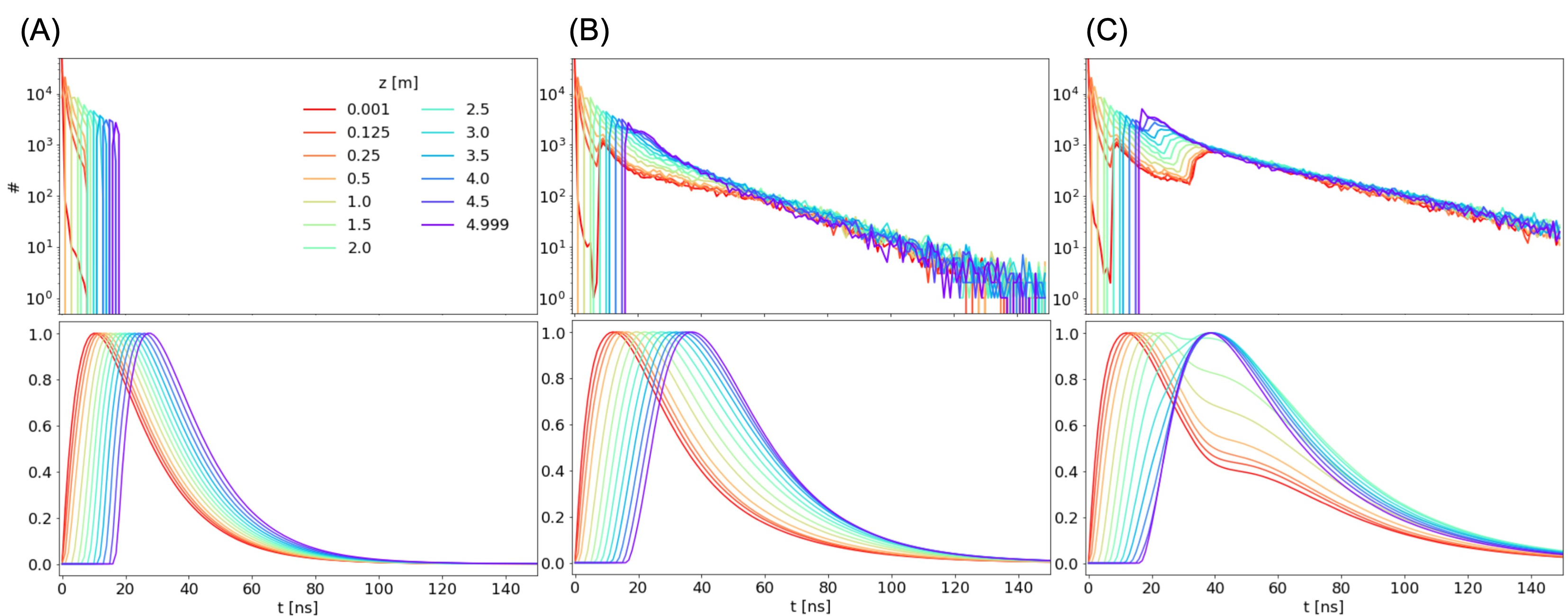
The time response of the TPC results from the time profile of the gas scintillation (fig. 2, top-left panel) coupled to the distribution of arrival times at the photosensor including all reflections. Geant4-simulated time profiles for point-like energy deposits are shown in figure 6 for the configuration without reflectors (A), reflective field-cage (B) and reflective field-cage and anode (C), for different positions of the light source within the chamber. The top-row panels show the time profiles from photon-tracing, while the bottom row shows the full TPC response including the gas scintillation profile (and arbitrarily normalized to one).
In the following, time and energy resolution will be assessed through an event-by-event analysis, performing a fit of the simulated pulses to signal templates (obtained from high-statistics simulations as in figure 6), and leaving the pulse time and amplitude free. It is shown later in section 4.1 that a 4–5 ns sampling (about twice the Nyquist sampling criteria in present conditions) preserves the pulse information, and it has been chosen hereafter. To avoid discretization artifacts, the time sampling is set to start asynchronously, event by event.
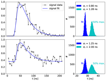
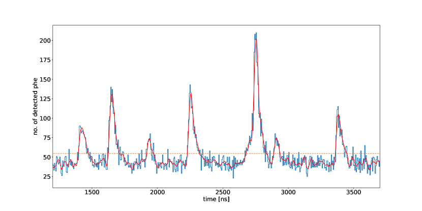
Examples from the fitting procedure for 5 MeV deposits under different dark-count levels are shown in figure 7 (left), which also provides (right panel) the distribution of reconstructed pulse-times obtained from the fit. It should be noted that, in the absence of experimental data, it is difficult to evaluate (and probably futile) the extent to which the shape of the pulse must be known prior to performing the peak-fitting routine. However, as suggested by fig. 6, and confirmed later for extended tracks, the TPC concept described here leads to very similar scintillation pulses for any particle type and position within the chamber. As a worse-case scenario, fig. 7 shows as well the distribution of reconstructed times when considering a shape-independent estimate (in this case, the time at 50 % of the signal maximum). For reference, in configurations A and B, a simpler template based on a bi-exponential signal convoluted with a Gaussian response of width and zero mean ( was employed, too:
| (4) |
This lead to very similar results compared to the exact template.
3.4 Detection threshold
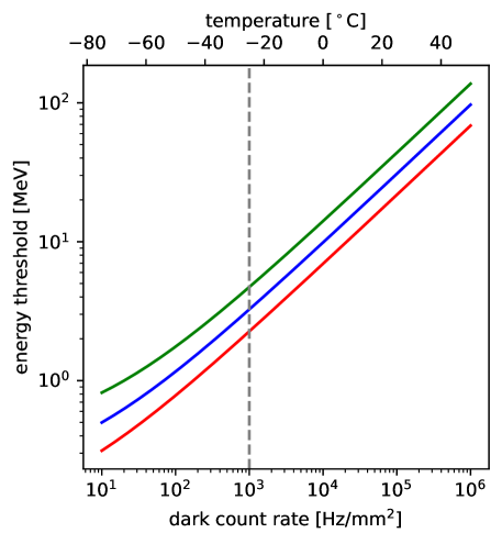
The minimum particle energy needed to enable detection of the primary scintillation signal can be estimated by defining the 5 sensitivity of the SiPM array as the average upper limit (computed here using the Feldman-Cousins frequentist prescription) that would be obtained by an ensemble of measurements with the expected background (the photosensor’s DCR) and no true signal. Figure 8 shows the energy threshold as a function of the DCR, for an event occurring at around mid-chamber in configuration B (Teflon-lined TPC), and different photosensor coverage.
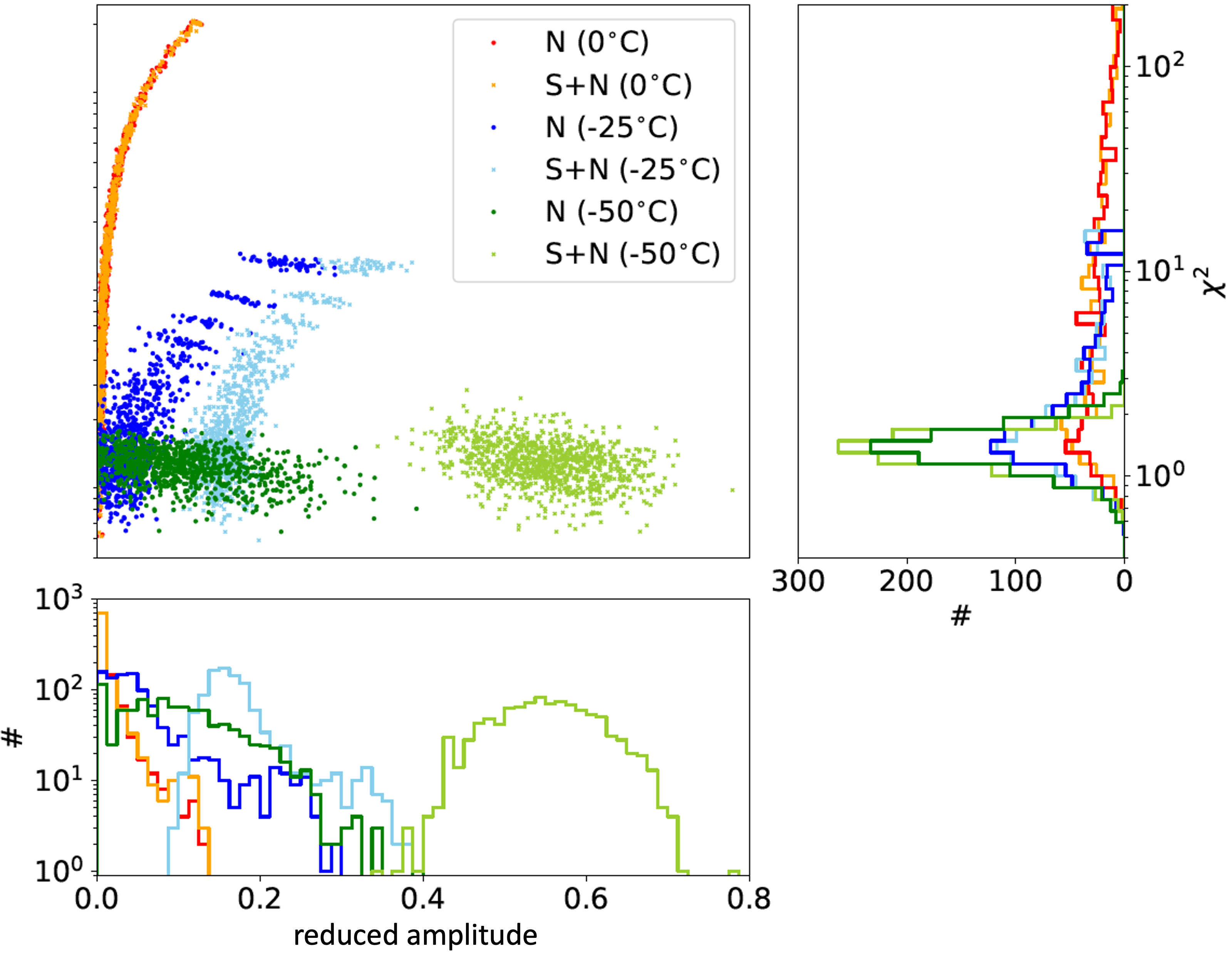
Another way to analyze the situation, without any prior on the arrival time of the pulse, is to consider how the reconstruction performs both on a baseline given by dark rate alone and on an actual pulse superimposed on such a baseline (chosen to be 200 ns wide). The obtained vs amplitude plots allow determining when a signal can be confidently identified (fig. 9): for 5 MeV deposits at the center of a Teflon-lined TPC and a temperature of around \celsius, both signal and baseline events can be well separated (dark and light-blue dots), becoming indistinguishable at C (red and yellow dots). Going down to \celsius, the two distributions become perfectly separated even when considering the amplitude alone.
3.5 Time and energy resolution for point-like tracks
The quality of the pulse-reconstruction procedure could be judged from the accuracy with which the event energy and time can be retrieved. The top panel of Figure 10 shows the spread () of the time distribution, while the bottom panel shows the relative spread (/mean) of the amplitudes obtained from the pulse fit, as a function of the event energy. In both cases, a point-like event at mid-chamber is considered, in a Teflon-lined TPC (B). In the background-dominated region the performance improves as and tends asymptotically to , point at which all curves merge.
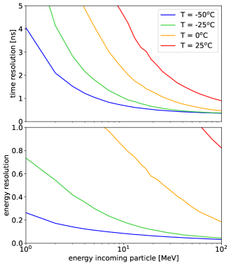
Energy resolution is an important figure in a high multiplicity environment, given that energy information is one of the criteria for matching scintillation and ionization signals in order to assign the time of the interaction to an event. The energy resolution from the ionization signal plays little role, as it is expected to be much better than in the scintillation channel: it improves approximately with the square root of the number of detected carriers, that is more than one order of magnitude higher in the ionization channel than in the scintillation one, in the gas conditions discussed. Considering for illustration the average energy lost by a high-energy electron or muon stemming from a charged-current interaction (about 50 MeV on a 5 m path in argon at 10 bar), figure 10 (bottom) indicates that 7% variations in energy loss in the chamber would be identified and correctly assigned. For low-energy hadrons fully contained in the TPC and without accompanying lepton (e.g., from a neutral-current or neutron interaction), the energy resolution level amounts to 18% at 10 MeV. The ability to do pulse reconstruction in a high multiplicity environment is discussed later in text.
When the matching between ionization and scintillation signals can be accomplished for an interaction inside the TPC, the time retrieved from the latter enables different capabilities, depending on the achievable resolution: (i) performing spill-association, (ii) -determination ( cm/s -scale in gas) and (iii) vertex assignment of neutral events (expectedly, the shortest time scale of practical use). In particular, the study in DUNE:2021tad indicates that neutrons from neutral-current interactions can be well assigned to the interaction vertex if their time-of-flight can be measured to ns accuracy. Figure 10 (top panel) indicates that this time-resolution value may be reached for MeV energy deposits at mid-chamber, if the SiPM plane is cooled down to \celsius. Focusing on this observable, fig. 11 presents the time resolution as a function of the DCR (bottom axis), and the corresponding operating temperature of the SiPMs (top axis), for the three configurations discussed. The study has been done for point-like deposits of 5 MeV (a bit above the energy threshold estimated in previous sections). The dashed vertical line indicates the proposed operating temperature ( \celsius).
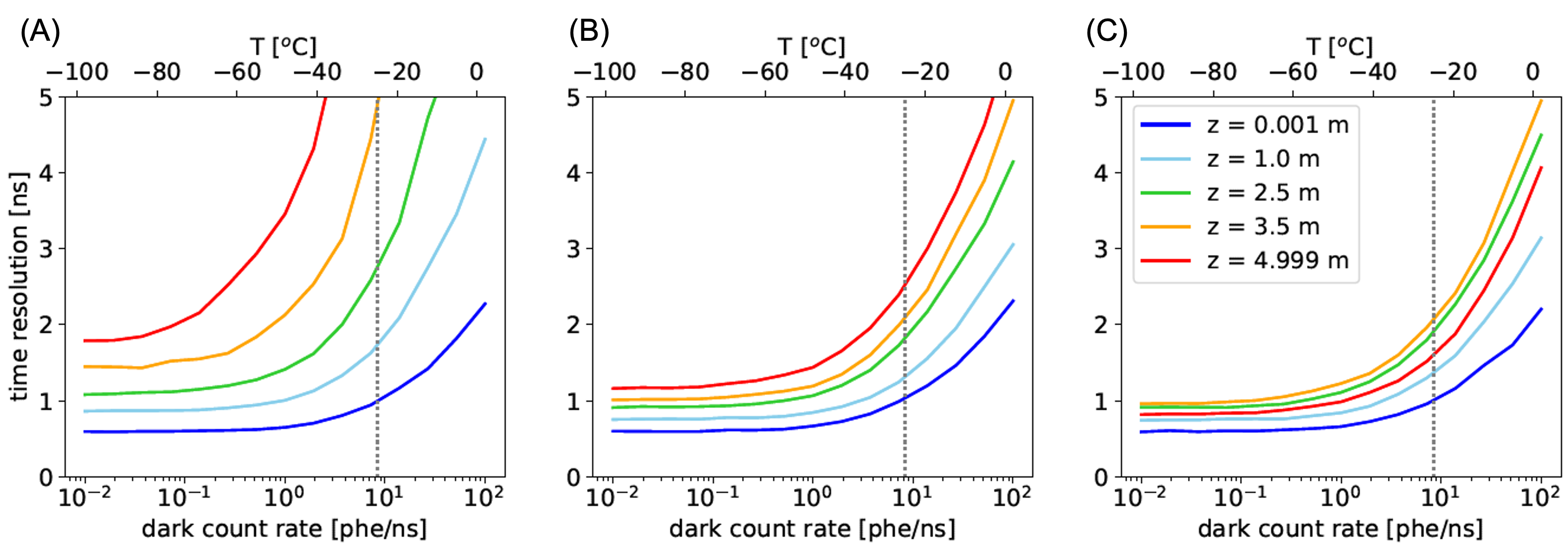
It can be noted that, from the point of view of the time resolution, the addition of a reflector at the anode is of little advantage as the anode-reflected light contributes little to timing except for events close to the anode (red line). When using reflectors, time resolution is situated in the range 1–2.5 ns at \celsius, whereas obtaining a comparable performance in the absence of them would require operation close to \celsius. An improvement of about a factor of 2 can be obtained for operation at \celsius in configurations B and C (centre and right panels in fig. 11), a performance that cannot be matched in the absence of reflectors no matter the operating temperature (left plot in fig. 11).
3.6 Response to extended tracks
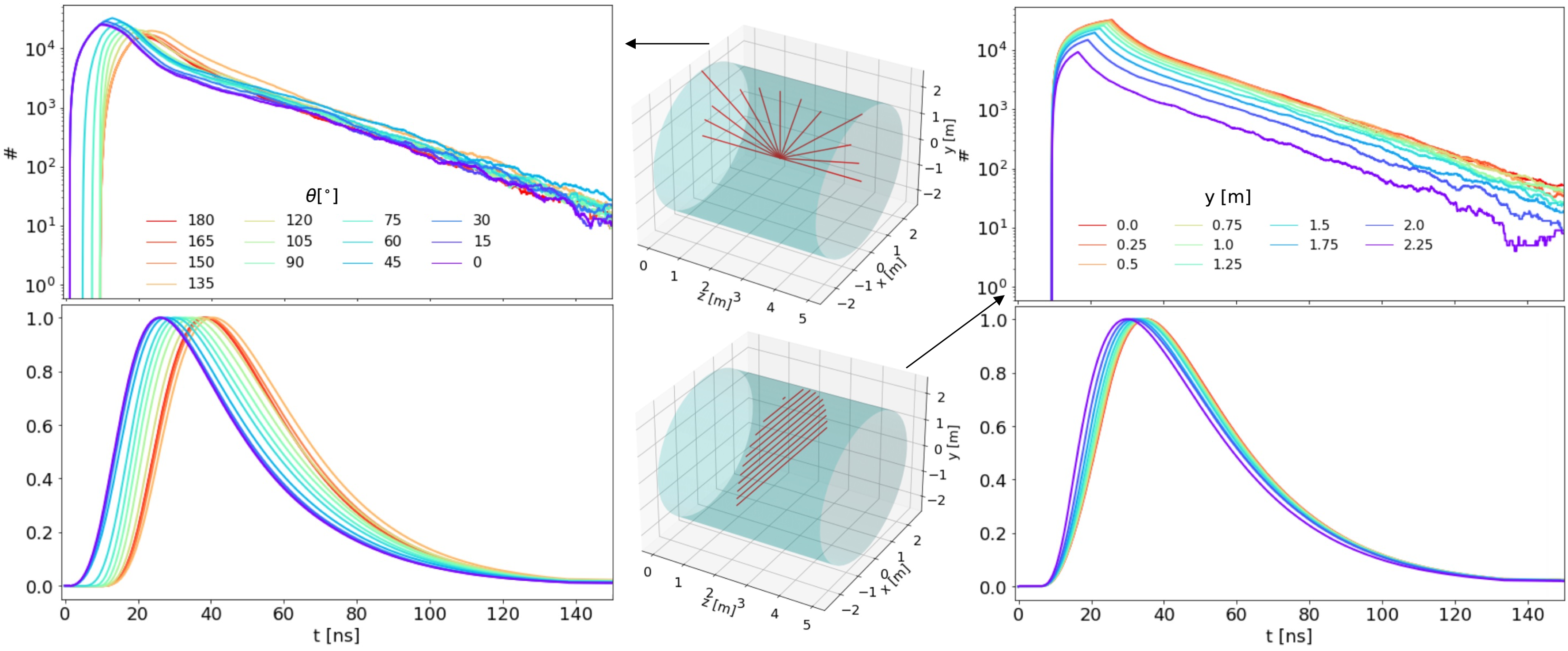
Background muons from neutrino interactions in the rock upstream of the TPC can be expected, entering it at different heights () and values of the drift coordinate (). On the other hand, leptons produced inside the chamber from charged-current interactions will be emitted at vastly different angles and interaction points. We choose such external and internal muons as our study case. Illustratively, figure 12 shows the simulated time distributions before (top panel) and after (bottom) including the time profile of the Ar/CF4 scintillation. Configuration B (Teflon-lined field cage) has been chosen again for our investigations. For internal muons, tracks have been generated at mid-chamber in varying angles (left), whereas for external muons different track heights are considered, parallel to the cathode plane and at the middle of the TPC (right). Even as the Geant4 pulses are widened due to the time elapsed by the muon crossing the chamber, the scintillation profile is still the dominant effect in the final pulse shapes, that are hence very similar to the ones obtained for point-like particles in figure 6.
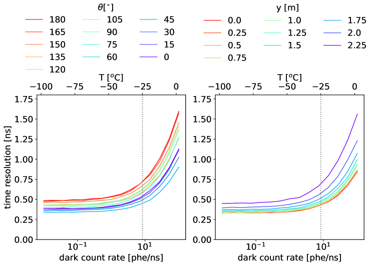
Following the procedure employed in previous sections, the resolution in the reconstruction of the interaction time has been obtained for typical topologies corresponding both to internal and external muons. The results in fig. 13 indicate that a sub-ns time resolution can be obtained in all cases, in the range 0.45–0.75 ns, if the SiPM plane is operated at around \celsius. This is a remarkable result, given the different event topologies and scintillation yields, as well as the delay arising from light reflection in a volume in which light needs 15 ns to cross it side to side.
3.7 In-spill reconstruction for high event multiplicities
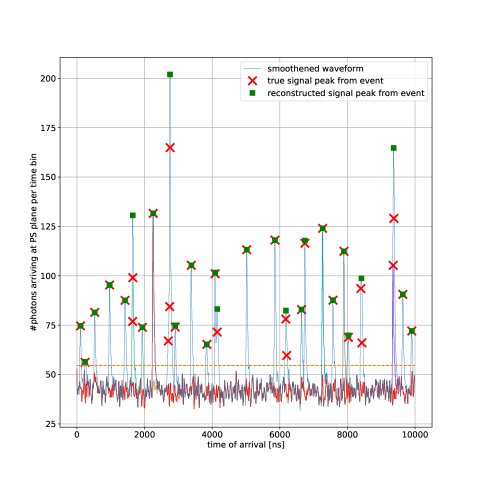
The ability to reconstruct multiple events per beam spill depends on the width of the primary scintillation pulse, whose largest contribution comes from the scintillation time profile of Ar/CF4, about 25 ns FWHM. To evaluate the reconstruction capabilities at high multiplicities, 10 to 100 muons with an energy of 1 GeV have been simulated, within a time window of 10 µs. They are assumed to cross the detector from the upstream direction, within an uniform irradiation field (i.e., they are external muons, according to the convention introduced earlier).
Before the waveform is scanned for peaks, a Savitzky-Golay filter is applied to reduce noise coming from the dark count (fig. 14 shows a zoomed section of the waveform). Peaks are searched for through an algorithm that uses a set of conditions on the signal shape, such as peak height, prominence and width. The height also serves as the signal threshold, which has been set to phe (approximately 1 MeV), where is the product of the average DCR per ns (at \celsius) times the sampling bin, which has been set to 5 ns for this study. Further, a peak candidate is required to have a prominence of 4.1 phe and a width of more than 2 ns, measured at 80% relative distance to the peak. With these conditions, the purity of the peak-finding algorithm reaches 100% well up to 100 muons per spill, with the efficiency remaining above 80% for a multiplicity of muons (fig. 15). These efficiency numbers are roughly compatible with a baseline occupancy estimated from the width of the scintillation pulses of about .
From fig. 15, it is clear that, with the energy resolution values estimated previously for muons, the assignment of the reconstructed pulses to the ionization/track counterpart will become problematic for multiplicities of the order of few 10’s every 10 µs. One might anticipate the use of any residual pulse-shape information or spatial correlations between the ionization and scintillation signals to perform the matching, as well as external time-tagging (if available), but the result of this procedure is setup-dependent and therefore beyond the scope of this study. On the other hand, for neutrino interactions inside the TPC, that are the subject of this work, we expect that the fluctuations of the hadronic component in both neutral and charged current interactions, as well as the variations stemming from the different interaction points, would yield a much larger range of event energies and topologies, simplifying the matching between the scintillation and ionization signals compared to a field of external muons.
4 Technical aspects
4.1 Photosensor response function and digitization
The photosensor response function (), signal-to-electronic-noise () and sampling time () can modify the performance presented in previous section. In order to address this, we consider light pulses from a canonical 5 MeV deposit in configuration B (Teflon-lined TPC) as before, this time at a position close to the cathode (blue line in fig. 11), to set the time scale precisely at 1 ns. Extending over previous analysis the is now introduced as a convolution over the Geant4-generated pulses, and the waveform template used for the fit includes the convolution with the as well. The decision to refer to the 1 ns landmark is partly arbitrary, however based on the observation that preserving time resolution preserves energy resolution and energy thresholds too.
We envisage SiPM ‘ganging’ DIncecco:2017bau in order to cover, in an affordable manner, an area of at least 7.5 m2 (38% coverage). In such a case, the depends on the parameters of the feedback and zero-pole cancellation loops of the amplifying electronics, and the equivalent SiPM-capacitance at its input. We consider response functions that can be realistically obtained when ganging 16 channels, as per an ongoing design based on LTSpice, including the ‘Corsi parameters’ for model S14161-6050HS (Hamamatsu) Corsi1 ; Corsi2 , following parallel passive ganging () and active summing (). The chosen 1” footprint of the sensor anticipates a lump sum of 12000 readout channels.
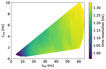
In simulation, a bi-exponential function of the type introduced in eq. (4) allows a good description of the , with two extreme cases being considered in the following: ‘fast’, where ns and ns; and ‘slow’, where ns and ns (defined from 10% to 90%). For illustration, fig. 16 provides the time resolution over a range of , values (sampled by Monte Carlo) including those two scenarios. Maximum variations stay well within a 30%. The small effect observed underlines the fact that the scintillation response of Ar/CF4, together with the delays due to light reflections in the TPC, dominate over the electronic response in the range of s considered.
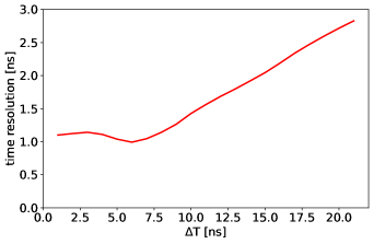
Another critical study is the determination of the optimum sampling time, that has a direct impact on the digitizing electronics, multiplexing strategy and cost. Again, as in previous section, the start time of the sampling process relative to the pulse has been randomized within a time bin, to mimic an asynchronous sampling. Fig. 17 shows that the time resolution is preserved for a time sampling corresponding to 7 ns, that motivates the value of ns chosen throughout the text.
Finally, we evaluate the impact of the electronic noise in the pulse reconstruction. We assumed a white-noise spectrum with a normal amplitude distribution centered around 0, whose -value is referred to as . The simulated pulses are reconstructed after smearing the amplitude in each 4 ns time-bin, following this noise model. The time resolution as a function of the ratio of the signal amplitude to noise () is shown in fig. 18. With continuous lines we present the performance when adding all electronic channels (totalling 12000 for the fill factor of discussed in text, 16-fold ganging, and assuming our 1 squared-inch baseline S14161-6050HS SiPM-sensor). With discontinuous lines we show the result of adding only channels that fired at a particular time.
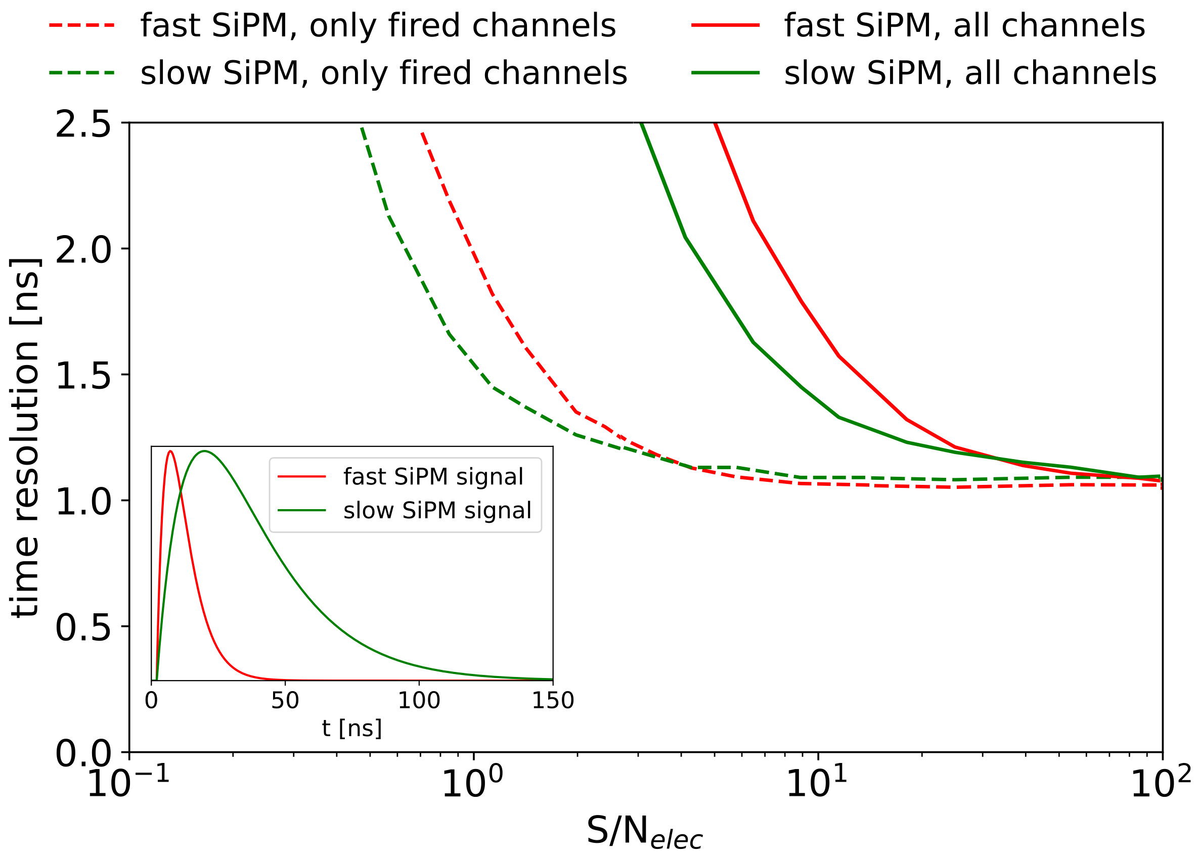
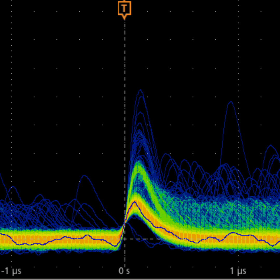
As the dark-rate occupancy in a 200 ns window is only about 3.5%/channel at \celsius, single-photon reconstruction should remain essentially unbiased, and a threshold may be in principle applied to every channel to select only those that fired in the given time window, if signal-to-noise allows. A signal-to-noise ratio around 5-10 should easily allow single-photon detection with a threshold at – over the noise level and, according to fig. 18-left, it should also keep the pulse-reconstruction (time resolution) of 5 MeV deposits largely unaffected. This seems well within reach of current technology as signal-to-noise ratios above 10 have been reported on areas similar to the ones discussed here DIncecco:2017bau . In case of incoherently adding all channels, on the other hand, a signal-to-noise value as high as 50 would be in principle needed to maintain good reconstruction down to 5 MeV energies (continuous lines in fig. 18-left), that seems extremely challenging. Clearly, any form of common noise should be suppressed, and differential or pseudo-differential readouts seem a must at the proposed scale. Fig. 18-right shows, for illustration, preliminary results obtained in conditions comparable to the ones discussed in text, for the same photo-sensor type and a ganging. An oscillogram of the dark rate pulses in persistency mode is presented, with the single, double and triple photon peaks being clearly visible. Only one of the two legs of the pseudo-differential outputs of the development board has been read out.
4.2 Light collectors
Even for an isotropic point-like light source, a hollow cylindrical reflector causes a bias in the landing angles on its endcaps, towards perpendicular incidence: the further the source is from the endcaps, the more likely a photon will land close to the normal (‘success bias’). This observation opens the possibility to use conventional light collectors to reduce the active area of the photocathode, potentially increasing the signal to DCR ratio and reducing cost.
A light collector would need to be optimized, ideally, for the most relevant positions of an event within the chamber. However, in a neutrino TPC that is expected to operate under highly-homogeneous neutrino and muon fields, the required depth-of-field of any light collection system corresponds to the TPC itself. Thus, the following simplifying assumptions have been made: (i) all light collectors are assumed to be identical, (ii) as the angular distribution of the landing photons was found to be rather independent from the radial position of the source, we consider photon sources distributed homogeneously over disks placed at different -distances from the photocathode. As usual, simulations in configuration B (Teflon-lined TPC) were chosen for reference.
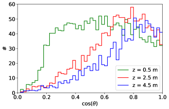
In the above conditions the aforementioned focusing effect is apparent in fig. 19, as events far from the photocathode show a relatively narrow distribution close to perpendicular incidence () while the distribution of events closer to the photocathode resembles isotropic emission down to some cutoff angle (coming from the photocathode size). This is indeed an appealing situation as it can be anticipated that the light collector at the photosensor plane will perform at its best when the light collection of the TPC is lower, and vice-versa.
We choose a classical Winston cone as an illustrative example since any other non-imaging optics is expected to follow closely the conclusions obtained for it. The critical angle defines the cone geometry as WinCone :
| (5) |
with referring to the area of the cone’s front face (‘window’), referring to the area of the cone’s rear face (‘photosensor’) and being the refraction index of the cone’s material. A good compromise between the light removed by the angular cut, the size of the Winston cone and the reduction in photosensor area seems to exist at around . We implement this condition through a PMMA-based Winston cone (), yielding a ratio / of 3. If aiming at (as in the concept proposed here, based on the S14161-6050HS SiPM model), a critical angle of implies that the length of the PMMA cone would be about 20 cm (and 12000 such cones would be necessary).
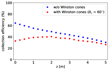
The total light collection efficiency of the TPC (configuration B) with and without Winston cones is shown in fig. 20 as a function of the distance of the source to the photosensor plane, in the ideal limit where transmission and reflection losses in the cone are neglected. As anticipated, the use of Winston cones makes the light collection much flatter overall, at the 30-40% level (red circles). Although, in view of the potential reduction of the active area of the photocathode ( in this case) this result is encouraging, it must be certainly taken with a grain of salt: the actual performance of such a light collector in terms of light transmission and reflectivity will require experimental verification. Additional gains are expected, on the other hand, for materials with higher refraction index such as sapphire.
4.3 Photosensor cooling
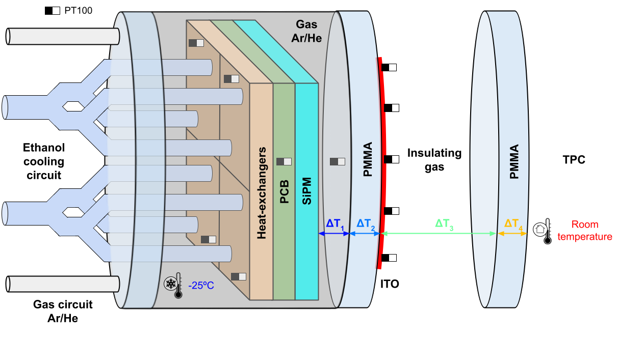
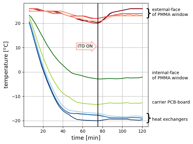
A temperature of \celsius is not alien to the operation of silicon-based photosensors PANDA:2008rpr and, with due precautions, it is high enough so as not to expect strong tin pest effects on the auxiliary electronic boards. Although several cooling strategies are possible, we discuss briefly a simple implementation that avoids the use of large vacuum vessels, and that might be practical when targeting operation near a pressurized system, at a modest power consumption. Given the necessity to avoid temperature gradients in the TPC, a combination of passive insulation and a mild active heating of the external window surface is proposed. Passive insulation could be enabled by 5 mm of pressurized Ar gas and a 20 mm-thick PMMA window, coated with an indium-tin-oxide (ITO) conductive film on its external surface, as shown in fig. 21 (top). The presence of a second PMMA window at the cathode plane ensures a buffer gas region for homogenization of residual temperature gradients over the windows. Fig. 21 (bottom) shows the experimental results for a 10 cm-diameter cryostat designed according to these principles, and cooled down to \celsius through an ethanol chiller. Upon turning the ITO on, the internal cooling power can be balanced and the system returned to stationary conditions, with a power consumption of about 100 W/m2. Over the entire photosensor region, this would amount to a modest 750 W (to which the electronics power needs to be added).
5 Summary of main results and conclusions
This work presents a feasibility analysis of the reconstructibility of the primary scintillation signal (‘’) in a 10 bar TPC based on Ar/CF4 (99/1), with capacity to house up to 1 ton of argon (5 m-height, 5 m-diameter). One of the main motivations for such a future system lies on the ability to accurately reconstruct low-energy particles emerging from neutrino interactions, that can not be well resolved by conventional means neither in condensed phase (too short) nor in pure gas phase (long enough to be resolved but not long enough to allow external time tagging), and thus bias the neutrino-energy estimate. A second motivation is technical: to increase the stand-alone tracking and timing capabilities of the TPC in order to provide independent means of disambiguation of the time and -position of the interactions. A third motivation, that has yet to be demonstrated at high pressures and will be discussed elsewhere, is the possibility to accomplish high-resolution 3D optical imaging of the particle tracks.
With this in mind, a part of our study was devoted to the reconstruction of light pulses from 5 MeV protons, that provides a reasonable proxy for the shortest track that can be reconstructed at the anode (tracking) plane in the gas conditions discussed (see, e.g., DUNE:2021tad ). We conclude that, upon lining the TPC field cage with PTFE/Teflon: i) neutral-current neutrino interactions with visible energy in the range 5-200 MeV as well as ii) charged-current neutrino interactions where the associated lepton would not be time-tagged externally or iii) stranded neutrons scattering off protons in the gas and transferring more than 5 MeV, would show a scintillation counterpart, allowing spill and vertex assignment, and ns-level time-of-flight determination. Additional technical requirements to achieve this are (i) a photosensor coverage of the cathode plane of at least 38% (7.5 m2), (ii) based on a SiPM-array (iii) at C, (iv) the readout grouped (‘ganged’) at least by a factor , probably. Non-withstanding the general academic interest for neutrino generators at understanding hadro-production down to nuclear binding energies, the present knowledge of neutrino-nucleus interactions seems to suggest a more modest energy-scale, around 20 MeV, as that of immediate interest. Two physical cases have been identified in DUNE:2022yni : (i) the reconstruction of the energy spectrum of protons modified due to final state interactions Theo1 ; Theo2 ; Theo3 , and (ii) multi-pion production Theo4 . Due to this (and keeping in mind that our understanding of neutrino interactions with nuclei is evolving) we discuss briefly the response to a 20 MeV hadron. In fact, in such a scenario the Teflon reflector around the field cage might not be necessary as such an energy would be above threshold for almost the entire chamber, with a time resolution below 2 ns. In the presence of Teflon-lining, a very modest 10% photosensor coverage would suffice to provide similar performances. If keeping the teflon lining and the proposed 38% coverage, operation of the photosensor plane close to C would become possible. Approaching an MeV threshold, on the other hand, will certainly require of all three assets (coverage, lining and cooling) simultaneously.
Finally, given that the reconstruction of leptons from charged-current interactions is essential for neutrino-oscillation experiments, we summarize the detector performance for ‘internal’ and ‘external’ muons. In this sense, and although for GeV-neutrino energies it can be expected that lepton time-tagging could be done with external detectors in most cases, the obtained results support the fact that a time-of-flight measurement of those (or any other minimum ionizing track) down to half a ns on a lever-arm of few meters is in principle possible. Conversely, for a typical drift velocity of the ionization electrons of cm/µs, an absolute -positioning within 30 µm can be anticipated.
Our work also provides a realistic, yet largely conceptual, path towards a practical implementation of the proposed photosensor system, involving the possible use of SiPM ganging, active cooling and Winston cones.
Acknowledgements
This research has received financial support from Xunta de Galicia (Centro singular de investigación de Galicia accreditation 2019-2022), and by the “María de Maeztu” Units of Excellence program MDM-2016-0692. DGD was supported by the Ramón y Cajal program (Spain) under contract number RYC-2015-18820. This research was also partly funded by the Spanish Ministry (‘Proyectos de Generación de Conocimiento’, PID2021-125028OB-C21).
Special thanks must be given to Alan Bross, Carlos Escobar and Adam Para (Fermilab) for encouragement and many insightful discussions.
References
- (1) D.R. Nygren, The Time Projection Chamber: A new 4 detector for charged particles, Tech. Rep. PEP-144 (1974).
- (2) H.J. Hilke, Time projection chambers, Rept. Prog. Phys. 73 (2010) 116201.
- (3) D.R. Nygren, Origin and development of the TPC idea, Nucl. Instrum. Meth. A 907 (2018) 22.
- (4) C. Rubbia, The liquid-argon time projection chamber: a new concept for neutrino detectors, Tech. Rep. CERN-EP-INT-77-8, CERN, Geneva (1977).
- (5) ICARUS-WA104, LAr1-ND and MicroBooNE collaboration, A Proposal for a Three Detector Short-Baseline Neutrino Oscillation Program in the Fermilab Booster Neutrino Beam, 1503.01520.
- (6) DUNE collaboration, Deep Underground Neutrino Experiment (DUNE), Far Detector Technical Design Report, Volume I Introduction to DUNE, JINST 15 (2020) T08008 [2002.02967].
- (7) C. Andreopoulos et al., Proposal to Measure Hadron Scattering with a Gaseous High Pressure TPC for Neutrino Oscillation Measurements, Tech. Rep. CERN-SPSC-2017-030, SPSC-P-355, CERN, Geneva (2017).
- (8) DUNE collaboration, A Gaseous Argon-Based Near Detector to Enhance the Physics Capabilities of DUNE, 2203.06281.
- (9) C. Cantini et al., Performance study of the effective gain of the double phase liquid Argon LEM Time Projection Chamber, JINST 10 (2015) P03017 [1412.4402].
- (10) A. Tesi, S. Leardini et al., The cryogenic RWELL: a stable charge multiplier for dual-phase liquid argon detectors, Eur. Phys. J. C 83 (2023) 979.
- (11) L. Olano-Vegas, I. Pardo, S. Leardini, M. Morales et al., Development of Fe2O3/YSZ ceramic plates for cryogenic operation of resistive-protected gaseous detectors, Front. Detect. Sci. Technol. 1 (2023) 1234229.
- (12) J.L. Pack, R.E. Voshall, A.V. Phelps and L.E. Kline, Longitudinal electron diffusion coefficients in gases: Noble gases, J. Appl. Phys. 71 (1992) 5363.
- (13) J. Alme et al., The ALICE TPC, a large 3-dimensional tracking device with fast readout for ultra-high multiplicity events, Nucl. Instrum. Meth. A 622 (2010) 316 [1001.1950].
- (14) NEXT collaboration, Electroluminescence TPCs at the Thermal Diffusion Limit, JHEP 01 (2019) 027 [1806.05891].
- (15) D. González-Díaz, F. Monrabal and S. Murphy, Gaseous and dual-phase time projection chambers for imaging rare processes, Nucl. Instrum. Meth. A 878 (2018) 200 [1710.01018].
- (16) T. Takahashi, S. Himi, M. Suzuki, J.-Z. Ruan(Gen) and S. Kubota, Emission spectra from Ar-Xe, Ar-Kr, Ar-N2, Ar-CH4, Ar-CO2 and Xe-N2 gas scintillation proportional counters, Nucl. Instrum. Meth. 205 (1983) 591.
- (17) J. Allison et al., Recent developments in Geant4, Nucl. Instrum. Meth. A 835 (2016) 186.
- (18) J. Allison et al., Geant4 developments and applications, IEEE Trans. Nucl. Sci. 53 (2006) 270.
- (19) Geant4 collaboration, Geant4—a simulation toolkit, Nucl. Instrum. Meth. A 506 (2003) 250.
- (20) C. Amsler, V. Boccone, A. Buchler, R. Chandrasekharan, C. Regenfus and J. Rochet, Luminescence quenching of the triplet excimer state by air traces in gaseous argon, JINST 3 (2008) P02001 [0708.2621].
- (21) R. Santorelli, E. Sanchez Garcia, P.G. Abia, D. González-Díaz, R.L. Manzano, J.J.M. Morales et al., Spectroscopic analysis of the gaseous argon scintillation with a wavelength sensitive particle detector, Eur. Phys. J. C 81 (2021) 622 [2012.08262].
- (22) P. Amedo, S. Leardini, A. Saá-Hernández and D. González-Díaz, Primary scintillation yields induced by particles in gas mixtures of Argon/CF4 at 10 bar, (in preparation).
- (23) P. Amedo, D. González-Díaz, F.M. Brunbauer, D.J. Fernández-Posada, E. Oliveri and L. Ropelewski, Observation of strong wavelength-shifting in the argon-tetrafluoromethane system, Front. Detect. Sci. Technol. 1 (2023) 1282854 [2306.09919].
- (24) B. Al Atoum, S.F. Biagi, D. González-Díaz, B.J.P. Jones and A.D. McDonald, Electron transport in gaseous detectors with a Python-based Monte Carlo simulation code, Comput. Phys. Commun. 254 (2020) 107357 [1910.06983].
- (25) P. Amedo, R. Hafeji, A. Roberts, A. Lowe, S. Ravinthiran, S. Leardini et al., Scintillation of Ar/CF4 mixtures: glass-THGEM characterization with 1% CF4 at 1-1.5 bar, Submitted to JINST (2023) [2312.07503].
- (26) M. Deptuch and T.Z. Kowalski, Gas multiplication process in mixtures based on Ar, CO-2, CF-4, Nucl. Instrum. Meth. A 572 (2007) 184.
- (27) C. Bault, A. Beschi, F. Brunbauer, D. González-Díaz, H. Muller, E. Oliveri et al., A survey on GEM-based readouts and gas mixtures for optical TPCs, in The 14th Vienna Conference on Instrumentation (VCI2016), 2016, https://indi.to/fVcZS.
- (28) F.M. Brunbauer, G. Galgóczi, D. Gonzalez Diaz, E. Oliveri, F. Resnati, L. Ropelewski et al., Live event reconstruction in an optically read out GEM-based TPC, Nucl. Instrum. Meth. A 886 (2018) 24.
- (29) F.M. Brunbauer, F. Garcia, T. Korkalainen, A. Lugstein, M. Lupberger, E. Oliveri et al., Combined optical and electronic readout for event reconstruction in a GEM-based TPC, IEEE Trans. Nucl. Sci. 65 (2018) 913.
- (30) F.M. Brunbauer, M. Lupberger, E. Oliveri, F. Resnati, L. Ropelewski, C. Streli et al., Radiation imaging with optically read out GEM-based detectors, JINST 13 (2018) T02006.
- (31) L.M.S. Margato, A. Morozov, M.M.F.R. Fraga, L. Pereira and F.A.F. Fraga, Effective decay time of CF4 secondary scintillation, JINST 8 (2013) P07008.
- (32) L. Margato, A. Morozov, L. Pereira, M. Fraga and F. Fraga, Effect of the gas contamination on CF4 primary and secondary scintillation, Nucl. Instr. Meth. A 695 (2012) 425.
- (33) ALICE collaboration, Upgrade of the ALICE Time Projection Chamber, Tech. Rep. CERN-LHCC-2013-020, ALICE-TDR-016, CERN, Geneva, Switzerland (2014).
- (34) F. Sauli, GEM: A new concept for electron amplification in gas detectors, Nucl. Instrum. Meth. A 386 (1997) 531.
- (35) F. Sauli, The gas electron multiplier (GEM): Operating principles and applications, Nucl. Instrum. Meth. A 805 (2016) 2.
- (36) S. Bressler, L. Moleri, A. Jash, A. Tesi and D. Zavazieva, The Thick Gas Electron Multiplier and its derivatives: Physics, technologies and applications, Prog. Part. Nucl. Phys. 130 (2023) 104029 [2303.01083].
- (37) M. Blatnik et al., Performance of a Quintuple-GEM Based RICH Detector Prototype, IEEE Trans. Nucl. Sci. 62 (2015) 3256 [1501.03530].
- (38) M. Chernyshova, K. Malinowski, T. Czarski, E. Kowalska-Strzęciwilk, P. Linczuk, A. Wojeński et al., Advantages of Al based GEM detector aimed at plasma soft-semi hard X-ray radiation imaging, Fusion Eng. Des. 146 (2019) 1039.
- (39) nEXO collaboration, nEXO Pre-Conceptual Design Report, 1805.11142.
- (40) NEXT collaboration, Dependence of polytetrafluoroethylene reflectance on thickness at visible and ultraviolet wavelengths in air, JINST 15 (2020) P11031 [2007.06626].
- (41) NEXT collaboration, Reflectance and fluorescence characteristics of PTFE coated with TPB at visible, UV, and VUV as a function of thickness, JINST 18 (2023) P03016 [2211.05024].
- (42) Hamamatsu Photonics Spain. Private communication, 2022.
- (43) A. Nepomuk Otte, D. Garcia, T. Nguyen and D. Purushotham, Characterization of Three High Efficiency and Blue Sensitive Silicon Photomultipliers, Nucl. Instrum. Meth. A 846 (2017) 106 [1606.05186].
- (44) MPPC—Technical Note, Tech. Rep. KAPD9008E02, Hamamatsu Photonics K.K. (September, 2023).
- (45) ECFA Detector R&D Roadmap Process Group, The 2021 ECFA detector research and development roadmap, Tech. Rep. CERN-ESU-017, CERN, Geneva, Switzerland (2020).
- (46) M. D’Incecco, C. Galbiati, G.K. Giovanetti, G. Korga, X. Li, A. Mandarano et al., Development of a Novel Single-Channel, 24 cm2, SiPM-Based, Cryogenic Photodetector, IEEE Trans. Nucl. Sci. 65 (2017) 591 [1706.04220].
- (47) PANDA collaboration, Technical Design Report for PANDA Electromagnetic Calorimeter (EMC), 0810.1216.
- (48) A. Morozov, M.M.F.R. Fraga, L. Pereira, L.M.S. Margato, S.T.G. Fetal, B. Guerard et al., Photon yield for ultraviolet and visible emission from CF4 excited with -particles, Nucl. Instrum. Meth. B 268 (2010) 1456.
- (49) M. Janecek, Reflectivity spectra for commonly used reflectors, IEEE Trans. Nucl. Sci. 59 (2012) 490.
- (50) I. Lindseth, A. Bardal and R. Spooren, Reflectance measurements of aluminium surfaces using integrating spheres, Opt. Lasers Eng. 32 (1999) 419.
- (51) A. Okumura et al., Prototyping Hexagonal Light Concentrators Using High-Reflectance Specular Films for the Large-Sized Telescopes of the Cherenkov Telescope Array, JINST 12 (2017) P12008 [1711.02367].
- (52) DUNE collaboration, Deep Underground Neutrino Experiment (DUNE) Near Detector Conceptual Design Report, Instruments 5 (2021) 31 [2103.13910].
- (53) F. Corsi et al., Electrical Characterization of Silicon Photo-Multiplier Detectors for Optimal Front-End Design, IEEE Nucl. Sci. Symp. Conf. Rec. (2006) 1276.
- (54) F. Corsi et al., Modelling a silicon photomultiplier (SiPM) as a signal source for optimum front-end design, Nucl. Instr. Meth. A 572 (2007) 416.
- (55) R. Winston, J.C. Miñano and P. Benítez, Nonimaging optics, Elsevier (2005).
- (56) J. Nieves, M. Valverde and M.J. Vicente Vacas, Inclusive nucleon emission induced by quasi-elastic neutrino-nucleus interactions, Phys. Rev. C 73 (2006) 025504.
- (57) O. Lalakulich, K. Gallmeister and U. Mosel, Neutrino- and antineutrino-induced reactions with nuclei between 1 and 50 GeV, Phys. Rev. C 86 (2012) 014607.
- (58) U. Mosel, O. Lalakulich and K. Gallmeister, Energy reconstruction in the Long-Baseline Neutrino Experiment, Phys. Rev. Lett. 112 (2014) 151802.
- (59) U. Mosel, O. Lalakulich and K. Gallmeister, Reaction mechanisms at MINERVA, Phys. Rev. D 89 (2014) 093003.