[1]\fnmShubhan P. \surPatni \equalcontThese authors contributed equally to this work.
These authors contributed equally to this work.
[1]\orgdivDepartment of Cybernetics, Faculty of Electrical Engineering, \orgnameCzech Technical University in Prague
2]\orgdivDepartment of Mechanics, Biomechanics and Mechatronics, Faculty of Mechanical Engineering, \orgnameCzech Technical University in Prague
Evaluating online elasticity estimation of soft objects using standard robot grippers
Abstract
Stiffness or elasticity estimation of everyday objects using robot grippers is highly desired for object recognition or classification in application areas like food handling and single-stream object sorting. However, standard robot grippers are not designed for elasticity estimation. In this work, a professional biaxial compression device was used as a control setup to study the accuracy with which material properties can be estimated by two standard parallel jaw grippers and a force/torque sensor mounted at the robot wrist. Using three sets of deformable objects, different parameters were varied to observe their effect on measuring material characteristics: (1) repeated compression cycles, (2) compression speed, and (3) the surface area of the gripper jaws. Gripper effort versus position curves were obtained and transformed into stress/strain curves. The modulus of elasticity was estimated at different strain points. Viscoelasticity was assessed using the energy absorbed in a compression/decompression cycle, the Kelvin-Voigt, and Hunt-Crossley models. Our results can be summarized as follows: (1) better results were obtained with slower compression speeds, while additional compression cycles or surface area did not improve estimation; (2) the robot grippers, even after calibration, were found to have a limited capability of delivering accurate estimates of absolute values of Young’s modulus and viscoelasticity; (3) relative ordering of material characteristics was largely consistent across different grippers; (4) despite the nonlinear characteristics of deformable objects, fitting linear stress/strain approximations led to more stable results than local estimates of Young’s modulus; (5) to assess viscoelasticity, the Hunt-Crossley model worked best. Finally, we show that a two-dimensional space representing elasticity and viscoelasticity estimates is advantageous for the discrimination of deformable objects. A single-grasp, online, classification and sorting of such objects is thus possible. An additional contribution is the dataset and data processing codes that we make publicly available.
keywords:
Material property estimation; Deformable objects; Haptic object exploration1 Introduction
Although visual object recognition has seen tremendous progress in recent years, not all object properties can be perceived using distal sensing. In particular, physical object properties like stiffness, roughness, or mass are better perceived through manipulation. Object recognition from haptic exploration can be more robust as it is insensitive to lighting conditions and object attributes that may be irrelevant (e.g. color). Estimating and interpreting these properties are desirable in many application areas such as single-stream object picking for manufacture [1, 2] or recycling. Plastic, paper, and metal differ significantly in their material properties and sorting them through manipulation holds great promise [3]. Further, in application areas such as virtual/augmented reality [4], medical diagnosis through palpation of subcutaneous tissue [5], and during tele-operation for navigating unknown environments, deformable objects need to be perceived and handled.
Sanchez et al. [6] provide a survey of robotic manipulation and sensing of deformable objects. Objects are considered deformable if they have no compression strength (ropes and clothes) or have a large strain111For linear elasticity, this implies small Young’s modulus, e.g. less than 10000 kPa.. Additionally, classification based on geometry is presented. In this work, we leave objects of Type I-III (linear, planar, cloth-like) aside and focus on Type IV: triparametric objects—solid objects such as sponges or plush toys, which are also the least researched object type [6]. Computational costs when simulating these interactions are enormous.
In this work, we specifically focus on material elasticity and viscoelasticity, and to what extent it can be estimated online using common robot equipment like 2-finger grippers. Grippers are designed for grasping rather than stiffness estimation, and often lack tactile sensors at the fingertips, hence their ability to provide accurate estimates of physical quantities like the modulus of elasticity is limited. With the help of a professional biaxial compression testing device, we systematically assess the performance of these grippers and a force sensor at the robot wrist, under different settings.
This article is structured as follows. After reviewing related work, the essentials of physics of deformation are explained (Section 3). Sample objects and the measuring devices are described in Section 4, followed by Experiments and Results. We close with Conclusion, Discussion, and Future work.
The dataset including raw as well as processed data collected during the experiments in this work is publicly available [7, 8]. An accompanying video is available here: https://youtu.be/FCNV24ZcOnM.
2 Related work
Recent surveys of haptic or tactile robot perception are provided by [9, 10]. Li et al. [9] list the object and material properties that can be extracted via tactile perception: stiffness, friction, surface texture, thermal conductivity, and adhesion. However, Luo et al. [10] point out a gap between rapid development of tactile sensing hardware and insufficient knowledge about how to interpret the sensory information obtained. In this paper, we try to reduce this gap by exploring the data streamed from the sensors and extracting material properties that may improve the interactions between robots and objects. We focus on stiffness/elasticity and how it can be perceived through a pinch grasp (squeezing). For deformable objects, the same action also allows us to perceive another material property: viscoelasticity. The next subsections provide an overview of the latest research in estimating stiffness and viscoelasticity in a robotic setup, i.e. without the use of industrial precision measurement instruments but rather with sensors commonly integrated with robots—RGB-D cameras and tactile sensors that measure reaction force.
2.1 Object Discrimination from Tactile Feedback
Spiers et al. [11] used a two-finger compliant gripper with force sensors to classify objects of various shapes, sizes, and stiffness. Random forests were used for classification and the importance of different extracted features was evaluated. Delgado et al. [12] used the Shadow Hand to grasp deformable objects and computed the deformability ratio to infer the maximum force allowed to be exerted on the object. Hosoda and Iwase [13] used a human-like robot hand with artificial muscles and soft skin with tactile receptors as input to a recurrent neural network with context nodes for object classification. Industrial research in the area is focused towards recognising objects for improved grasping and manipulation. Gemici and Saxena [14] learned haptic representations of food items. Four actions were used to explore 6 object characteristics (hardness, plasticity, elasticity, tensile strength, adhesiveness, brittleness). Scimeca et al. [15] used a 2-finger gripper for mango ripeness estimation. Chin et al. [3] implemented a custom-made soft 2-finger gripper with pressure and strain sensors to automated recycling separation (paper, plastic, metal). Finally, most related to this work, Wang et al. [16] used the deformation cues from pinch grasps of different soft objects to classify them using Functional Principal Component Analysis (FPCA features).
2.2 Estimating Elasticity
Smardzewski et al. [17] employ a professional axial compression device for estimating the compressive modulus of elasticity, in line with the corresponding standards [18]. Such measurement is very different from practical robotics because of the speed of testing, the precision of the feedback, and the varying shapes and sizes of objects. Some works employ the Finite Element Method (FEM) to model the object based on deformation data. Frank et al. [19] estimated the stiffness by capturing the object via RGB-D camera, creating a three dimensional finite element mesh in simulation software, and then numerically optimizing the stiffness parameter of the mesh by minimizing the error between the simulated and observed deformations. This process was developed upon further in [20] which used the simulated model and obtained stiffness to compute the input force for any given deformation. Visual and haptic information was also combined in [21] to estimate mechanical parameters of soft tissue. Longhini et al. [22] used visual tracking of marker nodes placed on the surface of the deforming object to learn deformation models of various textiles for control and manipulation. Stress-strain models were used to gain information about deformable materials without explicitly extracting stiffness/elasticity values in [23]. Narang et al. [24] used feedback from the BioTac tactile sensor as input to a multi-layer perceptron network predict the deformation of the target object in simulation. The network was trained to convert feedback to deformation and vice versa via a latent space representation. This solution was applied to a medical scenario in [25] for estimating the variable stiffness of soft tissue. However, the finite element method comprises of optimizing the target parameter for a large number of nodes. It is computationally time consuming and cannot be employed for quick, online estimation. Further, these articles use the ‘poking’ action by pressing the object against a wall with a fingertip, while in this work, we employ ‘squeezing’ or pinching between the gripper jaws. Zaidi et al. [26] employed a fingertip contact model that also simulates the deformation of the target object. The stiffness and damping are computed at the contact point and used as parameters in the deformation simulation to estimate grasp stability. Haddadi et al. [27] used the Hunt-Crossley Dynamic model for real-time identification of contact environments. This method is quicker as compared to finite element methods because it regards the object as a whole rather than as a mesh of a large number of nodes. Only three parameters have to be computed from collected force vs. deformation data. Further, no visual mode is applied, the feedback is only from the gripper and attached force sensors. Bednarek et al. [28] did not use a robotic hand or gripper, but instead use a spherical tip with the OptoForce 3-axis optical force sensor. The time series from this sensor is processed using an LSTM employed for material classification. Yao et al. [29] used the compression action to create three-dimensional stiffness maps of household objects.
2.3 Our Contribution
The focus of this work is to investigate how much can be learned about objects from a few grasping/squeezing actions. The contributions of this work over the state of the art are the following.
-
1.
We use three different robotic devices (two parallel jaw grippers and one force/torque sensor at the robot flange) and systematically study the effect of the characteristics of the device itself and different parameters of the object compression process on the quality of the mechanical response curves.
-
2.
We test a large set of deformable objects and employ a professional biaxial compression device to provide control values.
-
3.
We assess the potential and limitations of robot grippers to gauge material elasticity—absolute values of Young modulus as well as relative ordering of objects by their elasticity.
-
4.
We study the viscolelastic properties of the objects through compression and decompression cycles at different speeds.
-
5.
The collected dataset including the code for data processing is made publicly available.
Finally, we draw conclusions that generalize beyond the specific devices used here and provide guidelines for practical elasticity estimation and deformable object discrimination using ordinary robot grippers.
3 Physics of deformation
3.1 Elasticity
If a force is exerted on an object, the object deforms and it’s dimensions change.222This section draws on [30, Ch. 9] Depending on the direction of the force, the object either compresses or elongates. In this work, we focus on axial compression as this mode of testing objects/materials applies to robot grippers. If the amount of compression, , is small compared to the length of the object, is proportional to the force exerted. This is sometimes referred to as Hooke’s law and can be written as
| (1) |
where F represents the force applied on the object, is the change in length, and k is a proportionality constant. This linear relationship is a good approximation for many common materials, but applies only up to a certain called the proportional limit. With additional compression, the linear relationship does not hold anymore, but up to the elastic limit, if the force is released, the object still fully returns to its original dimensions. The strain is the ratio of the change in length to the original length . It is proportional to the force applied and the original length, but also inversely proportional to the cross-sectional area. To eliminate the object’s size or shape, a constant of proportionality that depends only on the object material is desired. This is the elastic modulus or Young’s modulus, E:
| (2) |
where stress is the force (F) per unit area (A) and has thus units , or Pascals. For the soft materials in this work, we will use kiloPascals (kPa). Strain is a dimensionless quantity (no units).
3.2 Viscoelasticity
Soft objects like the polyurethane foams, for example, have an elastic component and a viscoelastic component. Due to molecular rearrangement, energy as heat is dissipated when a load is is applied and then removed, i.e. during a compression and decompression cycle. The strain rate is also time-dependent. These properties can be characterized by the hysteresis in the stress-strain curve or by models taking into account both elasticity and viscosity. These will be detailed below.
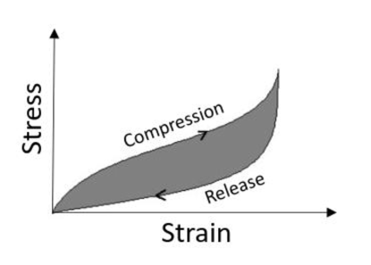
3.2.1 Calculating Viscoelasticity from Loop Enclosed Area
The “paths” for compression and decompression on the stress/strain plot are different for deformable objects. There is an area enclosed by these paths—the hysteresis loop—which corresponds to the amount of energy lost (as heat) as shown in Fig. 1. By plotting the energy lost versus the speed of compression/release we can obtain the viscoelastic coefficient .
3.2.2 Kelvin-Voigt Model
The Kelvin-Voigt model is a simple model that views every object as a spring and damper system arranged in parallel. The equation used to describe objects is a linear second order differential equation:
| (3) |
where is the applied force, is the stiffness/elasticity parameter, is the damping/hysteresis parameter, (t) and (t) are the deformation and rate of deformation respectively. Once a cycle of compression and release data has been collected in the form of deformation and force feedback, this data can be fit into Eqn. (3) using multi-variable linear regression to obtain values of and .
3.2.3 Hunt-Crossley Model
The Hunt-Crossley model expands upon the simple Kelvin-Voigt model by adding nonlinear power terms to the stiffness and damping components. Eqn. (3) is modified as
| (4) |
The added power terms accommodate the nonlinearities of the material. The term is a new parameter obtained as a result of the model. Since it is an exponential, instead of fitting data on this equation, we fit data on the logarithmic form:
| (5) |
4 Experimental setup
The set of object samples is described, followed by the robot grippers and a professional measuring device. Additional details about the experimental procedure and how the robot grippers were commanded can be found in a student thesis [31]. The code used to command the grippers and preprocess data is available at [32].
4.1 Objects set
We considered two sets of deformable objects. The first set, cubes and dice, consisted of 7 cuboid objects with a different size and degree of softness. The second set, polyurethane foams set, consisted of 20 polyurethane foam blocks of similar size, along with reference values for elasticity and density provided by the manufacturer. For all the objects used, the deformation can be regarded as elastic—objects returned to their undeformed shapes once the external force is removed. For some objects, this recovery was slow and they can be regarded as viscoelastic.
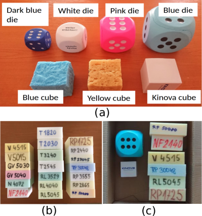
Cubes and dice set
This set of 7 soft objects is visualized in Fig.2(a) together with their names. Their dimensions are listed in Table 1. The “blue cube” is composed of the same material like the “blue die”—it has been cut out from another exemplar of the same object. “White die”, “kinova cube”, yellow cube”, and “blue cube” have roughly same dimensions but different material composition. The dataset was deliberately designed in this way such that the effects of material elasticity and object shape and size would be apparent in the results.
| Description | Dimensions [mm] |
|---|---|
| Kinova cube | 56x56x56 |
| Blue cube | 56x56x56 |
| Yellow cube | 56x56x56 |
| Blue die | 90x90x90 |
| White die | 59x59x59 |
| Pink die | 75x75x75 |
| Darkblue die | 43x43x43 |
Polyurethane foams set
To complement the “ordinary objects set”, we tested on another set of objects: 20 polyurethane foams (Fig.2(b)). These were samples provided by a manufacturer of mattresses and other foam products. The set includes hard insulation foams, memory foams, mattress foams and soundproof foams. Compared to the ordinary soft objects, “cubes and dice”, this dataset is much more uniform—both in terms of object dimensions and elasticity. The first two letters code for the standardized material type. For example, “RP” stands for Richfoam Polyether (STANDARD 100 by OEKO-TEX); the “T” series are polyurethane foams used to make furniture (hyper elastic polyurethane furniture foams [17]). Additionally, the complete code also contains density and one measure of the material’s elasticity: the compression stress value at 40% compression ( [18]) – see Table 2. However, we could not directly use these elasticity values as reference because the testing conditions prescribed by the ISO standard [18] cannot be met with robot grippers; moreover, these values have been obtained from samples tested within 72 hours after manufacture.
| Label | Dimensions [mm] | Density | |
|---|---|---|---|
| V4515 | 118x120x40 | 45 | 1.5 |
| V5015 | 119x120x42 | 50 | 1.5 |
| GV5030 | 118x119x40 | 50 | 3.0 |
| GV5040 | 118x118x39 | 50 | 4.0 |
| N4072 | 118x117x37 | 40 | 7.2 |
| NF2140 | 105x100x50 | 21 | 4.0 |
| T1820 | 125x125x50 | 18 | 2.0 |
| T2030 | 125x120x40 | 20 | 3.0 |
| T3240 | 123x123x50 | 32 | 4.0 |
| T2545 | 125x125x50 | 25 | 4.5 |
| RL3529 | 119x118x40 | 35 | 2.9 |
| RL4040 | 117x120x40 | 40 | 4.0 |
| RL5045 | 118x118x39 | 50 | 4.5 |
| RP1725 | 118x120x41 | 17 | 2.5 |
| RP2440 | 118x120x38 | 24 | 4.0 |
| RP27045 | 117x119x39 | 270 | 4.5 |
| RP30048 | 123x121x39 | 300 | 4.8 |
| RP3555 | 117x119x39 | 35 | 5.5 |
| RP2865 | 118x118x38 | 28 | 6.5 |
| RP50080 | 121x118x39 | 500 | 8.0 |
| \botrule |
Mixed set
Due to the reasons cited above, we need to obtain reference or control values for elasticity that the materials show in real time rather than their properties at manufacture time. An additional object set was formed from the previous sets, taking two “cubes and dice” (“Blue die” and “Kinova cube”) and 6 polyurethane foams – Fig.2(c). This set of 8 objects was tested on a professional biaxial compression setup (Section 4.4) to provide a reference for the measurements using robot grippers.
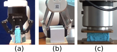
4.2 Robot setups
For experimentation, the following robotic setups are used: the Universal Robot UR10 with the OnRobot RG6 gripper and the Kinova Gen3 robotic arm with the Robotiq 2F-85 gripper. In addition, a force/torque sensor Robotiq FT300 was appended to the UR10 robot as a makeshift third setup.
4.2.1 Robotiq 2F-85
This gripper (Fig.3(a)) has 2 fingers with 85 mm stroke and offers a grip force from 20 N to 235 N. The fingertips dimensions can be approximated to a rectangle of . Velocity control was used during object compression. This is quoted in % of the maximum closing speed.
Action parameters: Four different nominal squeezing speeds were executed: 0.68% (approx. 1.6 mm/s), 14.45% (30 mm/s), 50.85% (80 mm/s), and 100% (131.33 mm/s).
Sensory channels: 2 channels: gripper position (gap between jaws 0–85 mm), motor current (A).
4.2.2 OnRobot RG6
The gripper (Fig.3(b)) has a 160 mm stroke and adjustable force and gripper status feedback (digital and analog). Gripper fingertips’ surface area is . Continuous closing while recording force feedback is not possible—it can only be emulated by incrementally increasing the force threshold.
Action parameters: None. The gripper was commanded to close with 1 mm increments until a certain force threshold was reached. Then, the threshold was incrementally increased. The force range was 25-120 N, with 1 N increments.
Sensory channels: 2 channels: gripper position (gap between jaws 0–160 mm) and flag for force threshold reached, plus the actual threshold (N). Data was collected only at the occasions when force threshold was reached.
4.2.3 Robotiq FT300
The UR10e manipulator is equipped with a Robotiq FT300 force/torque sensor (Fig.3(c)) that has a measuring range and for every axis in Cartesian coordinate system. The sensor noise for the force measurements should be 0.033 %.
Action parameters: None. We pressed the objects with the robot flange against the table with a speed of 30 mm/s.
Sensory channels: 2 channels: position in z-axis (mm) and force in the downward direction (N).
4.3 Gripper calibration
We used a S9M/500 N force transducer (strain gauge) along with a ClipX amplifier system (both from HBM) to calibrate the force feedback from the robotic grippers.
The Robotiq 2F-85 gripper outputs motor current in the range 0-1 A. Measurements were collected by manually operating the gripper as well as using velocity control with the range of speeds used later in the experiments. The relationship of force and current was found to be nonlinear and the best fit obtained was:
| (6) |
where i was the current reading (in Amperes) obtained from the gripper. Additionally, the closing speeds in % had to be calibrated and converted to mm/s (using the gripper position signal).
For the OnRobot RG6 gripper, feedback in Newtons is available. However, we have performed calibration as well and an approximately linear fit was obtained.
| (7) |
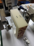
4.4 Professional biaxial compression setup
This setup was deployed to provide reference or control measurements for the “mixed set” of objects (Section 4.1). A biaxial experimental system Zwick/Roell was used (see Fig. 4). Samples were cyclically compressed between two antagonistic actuators, with a position resolution of . The actuator axes were connected to force sensors U9B from HBM with a 0.5 kN range, set to N, suitable for static and dynamic force measurements (accuracy class 0.2; IP67). On every side, a transparent pad of plexiglass was attached, with dimensions mm and mass of 60 g. The sample was placed between the pads and cyclically compressed and decompressed from both sides. Six cycles of compression and decompression were performed for every sample.
Action parameters: Compression speeds: One sample (RP1725) was tested with 1, 1.6, 10 30, 50, 80 mm/s. Remaining samples from the mixed set were tested with 1.6, 30, 50, and 80 mm/s. Decompression speed was the same as compression speed with the exception of sample V4515 which took long to restore its volume—1.6 mm/s decompression was used.
Sensory channels: Force (N) and displacement (mm) at every actuator.
5 Experiments and results
The presentation of experiments starts with plots of mechanical response curves from the different devices in their standard units, followed by a transformation into stress/strain curves. The effect of compression speed and precycling is analyzed. Young modulus estimates are then compared. Finally, viscoelastic property of the objects is studied.
Illustration of some of the experiments is available in the accompanying video.
5.1 Gripper effort and position
We compare the raw plots that can be obtained in the standard operation mode of every robotic device, as shown in Fig. 5 for the cubes and dice. No preprocessing or filtering of the data is applied. On the x-axes, object compression proceeds from right to left, as the gripper width decreases. Contact with the object is not detected and as the objects have different width, the curves corresponding to gripper effort start rising at different locations.
For the Robotiq 2F-85 gripper, 50% compression speed (approx. 79 mm/s) was used. Motor current is plotted against the gripper width. For the OnRobot RG6 gripper, force feedback can be retrieved only during discontinuous object compression with incremental adjustment of the force threshold. During measurements with the FT300 sensor, the robot arm was commanded to press downward against the object with a speed of 30 mm/s.
From Fig. 5, it is apparent that the mechanical response curves from all three devices have similar characteristics. The force/torque sensor (Fig.5(c),(f)) delivers the most clean data. The lines on the OnRobot RG6 plot (Fig.5(b),(e)) are noisy and not monotonic. This is because they were not collected during continuous compression of the objects, but through incremental increasing of the force threshold. The least accurate response curves come from the Robotiq 2F-85 (Fig.5(a),(d)), mainly because there are too few data points (combination of limited sampling rate and high speed of compression).
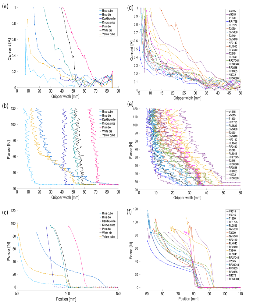
The 20 polyurethane foams constitute a more homogeneous object set, with similar dimensions and a narrower range of elasticity. Similar observations about the precision and continuity of data can be made for the deformable objects set and the polyurethane foams set.
5.2 Stress/strain response curves
To estimate material elasticity, the stress/strain relationship during compression of the material in question needs to be obtained (see Section 3 and Eqn. (2)). The key requirement is to detect the moment of contact of the gripper with the object, which marks the beginning of the stress/strain curve; the gripper width corresponds to . To recognize the moment of contact, the force/effort needs to be measured, which is necessary at any rate to obtain stress. The accuracy of contact detection affects the results and is gripper dependent. Position can typically be measured accurately and thus obtaining strain as is straightforward. To obtain stress as Force/Area, the surface area will be the smaller from the gripper jaws and the side of the object. The crucial part, however, is the (compression) force. If force is not directly available from the gripper, its calibration is necessary (Section 4.3).
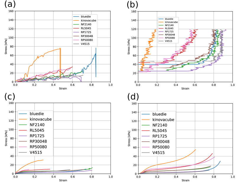
After collecting raw compression data on the robotic setups from both the objects set and the polyurethane foams set, the mixed set of foams and cubes was created (Section 4.1) and tested on a professional biaxial measuring device (Section 4.4). The stress/strain curves are shown in Fig. 6. The curves from the professional setup, Fig.6(d), will serve as reference. We observe that the samples are clustered with the “Kinova cube” being the least elastic material, followed by RL5045 and RP50080 foams. The rest of the samples occupy the bottom of the plot. This clustering is apparent also on the data from the RG6 gripper, Fig.6(b), and the FT300, Fig.6(c); it is less pronounced for the 2F-85 in Fig.6(a). The nonlinear response visible in the feedback recorded by the professional setup is partially preserved in the plots from the other devices. An important observation is the range on the y-axis. The absolute values of stress differ significantly, which limits the possibilities of estimation of the real value of the modulus of elasticity. The 2F-85 values seem most in line with the professional setup; the FT300 is underestimating the stress by approximately a factor of 2; the RG6, on the other hand, is overestimating the stress by the same factor. For estimation of real values of elastic moduli, such discrepancy is problematic.
5.3 Effect of compression speed and precycling
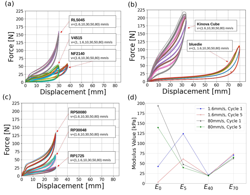
The ISO standard for low-density polymeric materials [18] prescribes that samples be compressed at a speed of 1.67 mm/s and that the stress/strain characteristics should be evaluated during the 4th compression cycle. To assess the effect of these parameters, we first used the biaxial professional setup. The compression and, in this case, also decompression curves for the objects of the mixed set are shown in Fig. 7, (a)-(c). Note that the upper part of every curve corresponds to compression. With higher speeds, the difference between the compression and decompression curve (hysteresis) is bigger. Individual compression cycles (1-6) do not have a significant effect on the overall shape. Fig.7(d) shows how the estimated modulus varies at different values of strain and with compression speed and cycle.
5.4 Young’s modulus
For the materials we tested, the stress/strain curves are nonlinear. Therefore, the modulus of elasticity will be different at different points on the curve. Thus, we estimate at different values of strain (0%, 5%, 40%, and 70%) by locally estimating the gradient, and a “linear” modulus that assumes the whole curve is linear.
5.4.1 Estimating Young’s Modulus from robot gripper data
From the professional setup, we obtain on average 4000 points per compression-and-release cycle. In comparison, the data from the robot grippers—OnRobot RG6 and Robotiq 2F-85—consists of only 200-300 points per cycle. Thus, the feedback from the grippers is sparse and visibly discrete in nature. Further, signal noise is significant. This noise may arise because of factors such as rough initial contact and release or resistance from the opposite jaw. Hence, prior to modulus estimation, the feedback is filtered using the Savitzky-Golay filter which smooths data using least-squares polynomial fitting on smaller window sizes. For the analysis of OnRobot RG6 data in this section, calibrated force values (Section 4.3) are used.
To find the modulus at any chosen strain percentage, we create a neighborhood around the strain value and find the slope of the best fit line in that neighborhood using scikit-learn’s LinearRegression module. To ensure that the best fit line obtained is actually representative of the slope at the chosen point, we vary window sizes to obtain the highest correlation as a measure. It is observed that this vs. window size variation is consistent in shape for the modulus values obtained at 40% and 70% strains. As shown in Fig.8(a), it can be seen that smaller window sizes have the highest scores at 40% and 70% strain. Alternatively, the scores for the best fit lines near the 0% and 5% strain values are very poor.
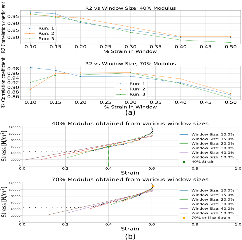
The window size for our best fit lines was fixed at 10% strain on either side. All results obtained from the robotic grippers are based on this window size.
5.4.2 Estimating Young’s Modulus from Professional Setup
We calculate the modulus values from the data from the professional setup. Modulus at 0%, 5%, 40%, and 70% was estimated using linear regression. Also, a “linear” modulus was calculated for the entire curve. For one sample, RP50080, statistical tests (t-test) were conducted to assess whether the compression cycle or the speed affect the modulus estimation. For the moduli at 0% () and 5% (), significant differences between cycle 1 and cycle 5 (p=0.01) were found. For and , no significant differences were found. Statistical tests comparing moduli estimation between slow speeds (1-10 mm/s) and fast speeds (30-50 mm/s) were also conducted and no significant differences were found. See also Fig. 7.
The moduli and moduli for the mixed set of samples are shown in Table 3 (mean over compression speeds, first compression cycle only). The error is presented as a ratio between the standard deviation and the mean. Since the sampling was dense, approximately 2% window on both sides of the desired strain value was sufficient.
| Foam | [kPa] (Err) | [kPa] (Err) |
|---|---|---|
| Blue die | 6.783 (10.0%) | 45.609 (15.2%) |
| Kinova cube | 82.638 (17.9%) | 82.638 (17.9%) |
| NF2140 | 9.756 (10.2%) | 46.047 (18.6%) |
| RL5045 | 26.323 (4.5%) | 116.240 (14.5%) |
| RP1725 | 6.391 (8.6%) | 20.557 (29.0%) |
| RP30048 | 12.439 (5.7%) | 50.479 (20.6%) |
| RP50080 | 20.044 (3.53%) | 75.912 (9.9%) |
| V4515 | 9.952 (27.32%) | 42.400 (30.68%) |
5.4.3 Modulus estimation from all devices
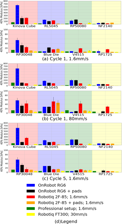
Data from all the different devices and different settings were used for Young modulus estimation on the mixed set sample. Estimations at 0% and 5% strain are not reported here as these were hard to obtain in all but the professional setup due to sparse sampling and presence of noise. At least five compression and decompression cycles were performed with every setting and the moduli were estimated at cycle 1 and cycle 5. Speed was varied for the professional setup and for the Robotiq 2F-85 gripper. In addition, to account for the effect of the surface area of the gripper jaws, the same pads (59 x 59 mm) used in the professional setup were mounted onto the OnRobot RG6 and Robotiq 2F-85 jaws as an additional setting.
The results of Young modulus estimation at 40% strain are shown in Fig. 9. The green bars in every subplot are from the professional setup and serve as reference. The following observations can be made: (1) no robotic device provides an accurate and reliable estimate of Young’s moduli corresponding to the values obtained from the professional setup; (2) adding the pads and thus increasing the surface area for the 2-finger grippers brings the absolute values closer to the reference, but adds noise to the estimation (disrupting the relative ordering of samples by elasticity); (3) the FT300 force sensor provides the most stable estimation, albeit the absolute values of Young’s modulus are significantly lower compared to the reference. This is consistent with the raw strain/stress curves in Fig. 6; (4) there is no clear effect of precycling (5th versus 1st compression cycle); (5) bigger compression speed degrades the estimation for the Robotiq 2F-85 gripper.
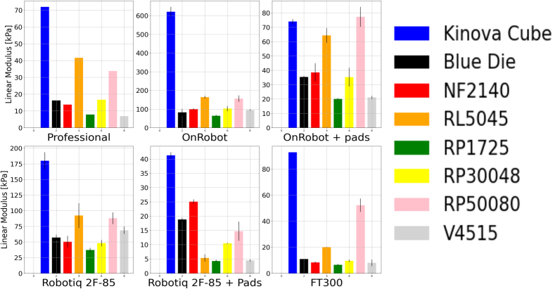
5.4.4 Linear modulus and relative elasticity estimation
The previous sections have shown that the capability of robotic grippers to deliver accurate estimates of Young modulus at different strain values are limited. Due to noise and limited resolution of the devices, local windows for estimation at e.g. 40% and 70% are unreliable. From a practical point of view, relative discrimination of objects based on their elasticity will often suffice. After experimentation, we propose to measure the stress/strain ratio over the whole compression area. This assumption is not correct since the mechanical response curves are clearly nonlinear, but it provides stable results in terms of ordering the samples by their elasticity, largely consistent across the different devices – see Fig. 10 and below:
| (8) |
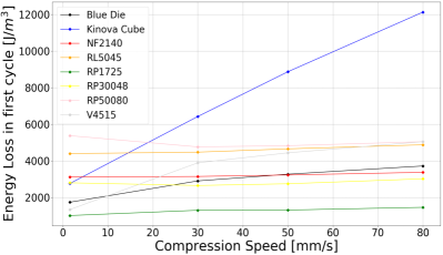
5.5 Viscoelasticity and the hysteresis loop
All the materials composing the mixed set have hysteresis loops (explained in Section 3.2.1) as can be seen in Fig. 7. The amount of energy lost is shown to be linearly proportional the compression speed in Fig. 11. The linear coefficient of the energy lost vs. speed graph is a characteristic of the material, and we label it . The values of this energy loss coefficient obtained from the professional setup are listed for all materials in Table 4. The materials fall approximately into two groups based on the values of . The viscous component is pronounced for the Blue die, Kinova cube, and the V4515 polyurethane foam. The Blue die and Kinova cube differ from the foams in that they are not completely homogeneous—they have a smooth outer shell that encloses the inside of the material and changes the properties. The difference in viscosity of the polyurethane foams may have to do with their porosity. Viscosity can provide and additional dimension next to elasticity to improve discrimination of soft materials.
| Foam | (x )[N.s.] |
|---|---|
| Blue die | 24.717 |
| Kinova cube | 119.487 |
| NF2140 | 3.267 |
| RL5045 | 6.314 |
| RP1725 | 5.392 |
| RP30048 | 2.960 |
| V4515 | 45.812 |
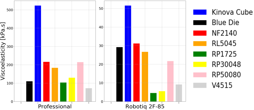
5.6 Measuring viscoelasticity with Robotiq 2F-85 gripper
All the models to characterize the viscous characteristics of the samples introduced in Section 3.2—area inside the hysteresis loop, Kelvin-Voigt model, and Hunt-Crossley model—were applied to the mixed set samples as measured by the Professional setup and the Robotiq 2F-85 gripper.333Note that the OnRobot RG6 gripper cannot be used since continuous object compression with different speeds while recording force feedback is not possible. Both devices were used to compress and release the samples with the following speeds: 1.6, 30, 50, 80 mm/s. To find parameters of the Kelvin-Voigt model and the Hunt-Crossley model, data from the first and fifth cycles for different speeds was fit into Eqn. (3) and Eqn. (4) individually and then averaged.
An overview of the results is in Fig. 12. The correspondence between the viscosity/damping parameter obtained from the professional setup and from the Robotiq 2F-85 gripper is not satisfactory for the area inside the hysteresis loop () and the Kelvin-Voigt model () is not satisfactory. Only the Hunt-Crossley model () provides a reasonable correlation—we will thus use this model in what follows.
5.7 Material discrimination from elasticity and viscoelasticity
Given the limited capabilities of robotic grippers to gauge material elasticity (Sec. 5.4) and viscosity (Sec. 5.6) alone, if the goal is online discrimination of deformable objects, it is advantageous to use both these quantities simultaneously. This is visualized in Fig. 13 with the values obtained from the professional setup and the Robotiq 2F-85 gripper side by side. One can observe that there is a good qualitative match between the two measuring devices and that the second dimension importantly aids the possibility of discriminating the objects. Performing actual classification is not in scope of this work but it is straightforward.

6 Conclusion, Discussion, Future Work
Robot grippers are primarily designed for grasping rather than for haptic estimation of material properties. However, if they could be employed for object discrimination by only squeezing and releasing a sample, it would have important application potential in areas like food handling and single-stream garbage sorting. In this work, we employ two standard industrial robot grippers with force feedback and, for comparison, a force/torque sensor at the robot wrist to press objects against the table. A sample of ordinary cube-like soft objects and a challenging set of polyurethane foams from a mattress manufacturer are tested. A subset of the objects is tested on a professional setup to provide control values.
In terms of gauging stiffness/elasticity, we found the following: (i) the robot grippers, even after calibration of the force feedback, were found to have a limited capability of delivering accurate estimates of absolute values of the modulus of elasticity (Young’s modulus) at different compression levels; (ii) precycling—measuring elasticity not on the first compression cycle but on the fourth or fifth as recommended by standards [18]—did not have a significant effect and hence data from the first compression cycle can be directly used; (iii) slower compression speeds are advantageous for estimation; (iv) relative ordering of the samples, is possible and largely consistent across the devices. Although the mechanical response stress/strain curves of the soft objects are nonlinear, in practice it proved more accurate not to attempt fitting gradients and estimating Young’s modulus at different compression levels. Instead, fitting a single straight line over the whole compression path gave the most stable results.
Soft objects are typically viscoelastic—energy is absorbed in a compression and release cycle. The viscosity, or damping, is dependent on compression speed. These characteristics can also be extracted provided that force can be measured during compression as well as release of the sample. Obtaining data from different gripper nominal speeds improves the estimation. In our case, the Hunt-Crossley model proved the most accurate.
In terms of the robot devices we tested, the Robotiq 2F-85 gripper is limited in its sampling rate, but it has the important capability to be able continuously measure the effort during a compression and release cycle. The effort is in motor current (A) and calibration is necessary to obtain force (N) to estimate the elastic modulus in real physical units. However, even after calibration, such estimation was not accurate. On the other hand, if only relative ordering or discrimination of viscoelastic objects is desired, this device will suffice. The OnRobot RG6 can only measure force when a set threshold is exceeded. The threshold then needs to be reset to continue compression. Such measurement is slow but sufficient to coarsely estimate material elasticity. However, the fact that no measurement during releasing is possible and that speed cannot be varied makes the measurement of viscolelasticity impossible. For comparison, we also show data from pressing an an object with the robot flange and measuring the resistance with a force sensor at the manipulator’s wrist. This proved accurate but may not be applicable in many situations when grasping an object is needed simultaneously with elasticity measurements.
Overall, this work provides a systematic investigation of the feasibility of online haptic discrimination of soft objects based on their viscoelastic properties using standard robot grippers. We provide guidelines, code, and dataset. A 2-finger parallel jaw gripper capable of measuring effort during compression and decompression of the sample is capable of discriminating deformable objects. We show that this is possible even for a challenging sample set like 20 similar polyurethane foams. Combining elasticity and viscoelasticity estimation is advantageous. For this, a couple of compression/decompression cycles at different gripper speeds works best. All the processing we used—detecting contact, obtaining the stress/strain curve, estimating elasticity, and fitting a Hunt-Crossley model—is white-box, simple (compared to finite element method modeling or to deep neural networks), and can work online. In the future, it can be complemented with existing visual-based methods. The viscoelastic properties perceived can be further used to devise appropriate manipulation policies [33, 14].
7 Declarations
Funding This work was co-funded by the European Union under the project Robotics and advanced industrial production (reg. no. CZ.02.01.01/00/22_008/0004590). Hynek Chlup is funded under grant no. GA23-06920S by the Czech Science Foundation (GA CR).
Competing Interests Not applicable.
Availibility of Data and Material All raw data is made available in our public data repository.
Code Availibility Code for the analysis of data is made available in our public code repository.
Ethics Approval Not applicable. \bmheadConsent to Participate Not applicable. \bmheadConsent for Publication Not applicable.
Author Contributions All authors contributed to the study conception and design. Material preparation, data collection and analysis were performed by Shubhan P. Patni and Pavel Stoudek. The first draft of the manuscript was written by Shubhan P. Patni and Pavel Stoudek and all authors commented on previous versions of the manuscript. All authors read and approved the final manuscript.
Acknowledgements We would like to thank Karla Stepanova for her inputs, and Bedrich Himmel for assistance with gripper calibration.
References
- \bibcommenthead
- [1] Papadopoulos, G. et al. On deformable object handling: multi-tool end-effector for robotized manipulation and layup of fabrics and composites. The International Journal of Advanced Manufacturing Technology 128, 1675–1687 (2023).
- [2] Zhang, S. & Zhang, Y. Determination method of stable grasping parameters for irregular sheet sorting. The International Journal of Advanced Manufacturing Technology 128, 2075–2085 (2023).
- [3] Chin, L., Lipton, J., Yuen, M. C., Kramer-Bottiglio, R. & Rus, D. Hosoda, K. (ed.) Automated recycling separation enabled by soft robotic material classification. (ed.Hosoda, K.) 2019 2nd IEEE International Conference on Soft Robotics (RoboSoft), 102–107 (IEEE, 2019).
- [4] Liu, L., Zhang, Y., Liu, G. & Xu, W. Variable motion mapping to enhance stiffness discrimination and identification in robot hand teleoperation. Robotics and Computer-Integrated Manufacturing 51, 202–208 (2018).
- [5] Scimeca, L. et al. Action augmentation of tactile perception for soft-body palpation. Soft robotics 9, 280–292 (2022).
- [6] Sanchez, J., Corrales, J.-A., Bouzgarrou, B.-C. & Mezouar, Y. Robotic manipulation and sensing of deformable objects in domestic and industrial applications: a survey. The International Journal of Robotics Research 37, 688–716 (2018).
- [7] Patni, S., Stoudek, P. & Hoffmann, M. Squeezing data and processing for mixed set (2021). URL https://osf.io/gec6s/?view_only=979775a79d934a0083a1b2008544183e.
- [8] Stoudek, P. Raw data from squeezing on deformable objects (2020). URL https://drive.google.com/drive/folders/16sUG-zCwCg5HIF7EbCTBqgsklw7-vOpg?usp=sharing.
- [9] Li, Q. et al. A review of tactile information: Perception and action through touch. IEEE Transactions on Robotics (2020).
- [10] Luo, S., Bimbo, J., Dahiya, R. & Liu, H. Robotic tactile perception of object properties: A review. Mechatronics 48, 54–67 (2017).
- [11] Spiers, A. J., Liarokapis, M. V., Calli, B. & Dollar, A. M. Single-grasp object classification and feature extraction with simple robot hands and tactile sensors. IEEE transactions on haptics 9, 207–220 (2016).
- [12] Delgado, A., Jara, C. A., Mira, D. & Torres, F. Filipe, J. (ed.) A tactile-based grasping strategy for deformable objects’ manipulation and deformability estimation. (ed.Filipe, J.) 12th International Conference on Informatics in Control, Automation and Robotics (ICINCO), 369–374 (IEEE, 2015).
- [13] Hosoda, K. & Iwase, T. Luo, R. (ed.) Robust haptic recognition by anthropomorphic bionic hand through dynamic interaction. (ed.Luo, R.) 2010 IEEE/RSJ International Conference on Intelligent Robots and Systems, 1236–1241 (IEEE, 2010).
- [14] Gemici, M. C. & Saxena, A. Lynch, K. (ed.) Learning haptic representation for manipulating deformable food objects. (ed.Lynch, K.) 2014 IEEE/RSJ International Conference on Intelligent Robots and Systems, 638–645 (IEEE, 2014).
- [15] Scimeca, L. et al. Dudek, G. (ed.) Non-destructive robotic assessment of mango ripeness via multi-point soft haptics. (ed.Dudek, G.) 2019 International Conference on Robotics and Automation (ICRA), 1821–1826 (IEEE, 2019).
- [16] Wang, L., Li, Q., Lam, J. & Wang, Z. Tactual recognition of soft objects from deformation cues. IEEE Robotics and Automation Letters 7, 96–103 (2022).
- [17] Smardzewski, J., Grbac, I. & Prekrat, S. Nonlinear mechanics of hyper elastic polyurethane furniture foams. Drvna industrija: Znanstveni časopis za pitanja drvne tehnologije 59, 23–28 (2008).
- [18] Polymeric materials, cellular flexible – Determination of stress-strain characteristics in compression, Part 1: Low-density materials (1986). URL https://www.iso.org/obp/ui/#iso:std:iso:3386:-1:ed-2:v1:en.
- [19] Frank, B., Schmedding, R., Stachniss, C., Teschner, M. & Burgard, W. Luo, R. (ed.) Learning the elasticity parameters of deformable objects with a manipulation robot. (ed.Luo, R.) 2010 IEEE/RSJ International Conference on Intelligent Robots and Systems, 1877–1883 (IEEE, 2010).
- [20] Sengupta, A., Lagneau, R., Krupa, A., Marchand, E. & Marchal, M. Regnier, S. (ed.) Simultaneous tracking and elasticity parameter estimation of deformable objects. (ed.Regnier, S.) 2020 IEEE International Conference on Robotics and Automation (ICRA), 10038–10044 (IEEE, 2020).
- [21] Boonvisut, P. & Çavuşoğlu, M. C. Estimation of soft tissue mechanical parameters from robotic manipulation data. IEEE/ASME Transactions on Mechatronics 18, 1602–1611 (2012).
- [22] Longhini, A. et al. Althoefer, K. (ed.) Edo-net: Learning elastic properties of deformable objects from graph dynamics. (ed.Althoefer, K.) 2023 IEEE International Conference on Robotics and Automation (ICRA 2023), 3875–3881 (2023).
- [23] Longhini, A. et al. Althoefer, K. (ed.) Elastic context: Encoding elasticity for data-driven models of textiles. (ed.Althoefer, K.) 2023 IEEE International Conference on Robotics and Automation (ICRA 2023), 1764–1770 (2023).
- [24] Narang, Y., Sundaralingam, B., Macklin, M., Mousavian, A. & Fox, D. Sim-to-real for robotic tactile sensing via physics-based simulation and learned latent projections. arXiv preprint arXiv:2103.16747 (2021).
- [25] Bickel, B. et al. Capture and modeling of non-linear heterogeneous soft tissue. ACM Transactions on Graphics (TOG) 28, 1–9 (2009).
- [26] Zaidi, L., Corrales, J. A., Bouzgarrou, B. C., Mezouar, Y. & Sabourin, L. Model-based strategy for grasping 3d deformable objects using a multi-fingered robotic hand. Robotics and Autonomous Systems 95, 196–206 (2017).
- [27] Haddadi, A. & Hashtrudi-Zaad, K. Real-time identification of hunt–crossley dynamic models of contact environments. IEEE Transactions on Robotics 28, 555–566 (2012).
- [28] Bednarek, J., Bednarek, M., Kicki, P. & Walas, K. Hosoda, K. (ed.) Robotic touch: Classification of materials for manipulation and walking. (ed.Hosoda, K.) 2019 2nd IEEE International Conference on Soft Robotics (RoboSoft), 527–533 (IEEE, 2019).
- [29] Yao, S. & Hauser, K. Althoefer, K. (ed.) Estimating tactile models of heterogeneous deformable objects in real time. (ed.Althoefer, K.) 2023 IEEE International Conference on Robotics and Automation (ICRA 2023), 12583–12589 (2023).
- [30] Giancoli, D. C. Physics Fourth edn (Prentice-Hall International, 1995).
- [31] Stoudek, P. Extracting material properties of objects from haptic exploration using multiple robotic grippers. Master’s thesis, Czech Technical University, Faculty of Electrical Engineering (2020).
- [32] Stoudek, P. & Mareš, M. (2021). URL https://gitlab.fel.cvut.cz/body-schema/ipalm/ipalm-grasping.
- [33] Arriola-Rios, V. E. et al. Modeling of deformable objects for robotic manipulation: A tutorial and review. Frontiers in Robotics and AI 7, 82 (2020).