Also at ]Interdisciplinary Centre of Energy Sciences, Indian Institute of Science, Bengaluru, 560012, India.
Dynamics of Soap Bubble Inflation
Abstract
Bubbles have always captivated our curiosity with their aesthetics and complexities alike. While the act of blowing bubbles is familiar to everyone, the underlying physics of these fleeting spheres often eludes reasoning. In this letter, we discuss the dynamics of inflating a soap bubble using controlled airflow through a film-coated nozzle. We assess and predict the rate of inflation by varying the source pressure. Visualising the previously unexplored internal flow reveals that air enters the bubble as a round jet, emerging from the nozzle opening and impinges on the expanding concave bubble interface to form a toroidal vortex. Several scaling laws of the associated vortical flow spanning the entire bubble and the vortex core are reported. The observed dynamics of this bubble-confined vortex ring formation indicate universality in certain aspects when compared to the free laminar vortex rings.
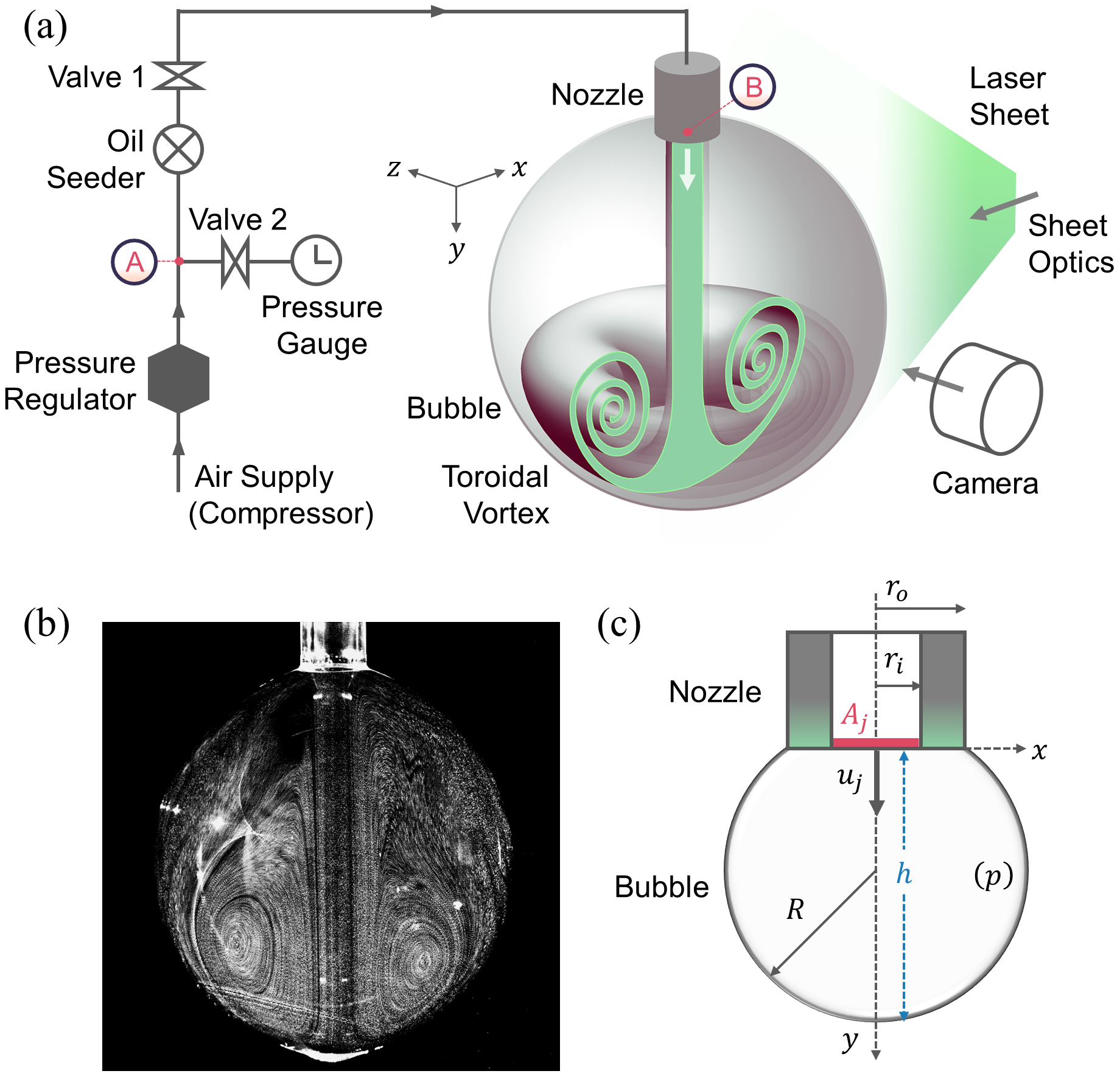
Soap bubbles have been a source of wonder for researchers and the general public alike for generations, yet our continued exploration still unveils nuances that keep us engaged with these iridescent objects [1]. Among these exciting features are the vivid interference patterns [2], bursting films [3], minimal surfaces [4] and even the demonstration of a soap bubble as an optical cavity to generate a laser [5]. This paper specifically delves into the physics of soap bubble inflation, revealing the remarkable flow that happens inside. Notably, the internal flow exhibits a toroidal vortex structure as illustrated in Fig. 1.
The dynamics associated with bubble inflation have been examined from different perspectives throughout the literature. In the most general sense, the soap bubble anatomy consists of a thin film of soap liquid stretching against a gas flow. This soap film is usually pinned or held over an aperture through which the air is introduced, enabling the inflation process. The aperture can be a ring or a wand, where a free jet or stream of gas is used for blowing the bubble [6, 7, 8, 9]. Another possibility is a closed configuration where an opening at the tube end with the gas efflux is the aperture over which the soap film is pinned [10]. These studies primarily focused on the motion or stretching of the soap film. It has been shown that in the case of blowing using a free gas jet, there exists a critical velocity beyond which a bubble forms and detaches from a soap film [6, 7]. Blowing a bubble through a constriction in a fixed mass system depicts an unstable growth of the bubble interface [10]. However, beyond these considerations, the associated internal flow structure of the gas phase being used for inflation is rarely explored or reported.
The soap films were also extended to study two-dimensional flows where the incumbent vortical dynamics were rigorously observed and studied for the flowing film [11, 12] and bubbles [13, 14]. This study, however, focuses on the vortical dynamics of the gas phase flow within a growing soap bubble.
The anatomy of an inflating bubble can be extended to other systems where a membrane or interface is stretched against a fluid flow. This involves problems spanning from filling a simple rubber balloon [15] to the flow focusing within microdroplets [16]. Containers like plastic bottles or glass vessels are produced by blow moulding, i.e. inflating a plug in a mould of a prescribed shape, where flow-induced cooling depends on the internal fluid motion [17]. Soft robotics and medical devices [18] involve controlled inflation and deflation of tubes, balloons or chambers, where a uniform flow and pressure distribution might be necessary. Furthermore, the membrane-based systems involving engulfment flows induced by forced membrane motion will also depict similar flow characteristics. The jellyfish-like locomotion [19, 20], the flow inside the heart chambers [21] or even artificial organs are a few examples.
For the aforementioned systems, the precise knowledge of internal flow dynamics of the fluid phase enclosed within a membrane-like entity is deemed necessary for a better understanding and control of the associated phenomenon. The exact flow conditions will differ vastly from our canonical bubble inflation problem; however, a prominent vortical structure is usually associated, either due to fluid-structure interaction or unsteady inlet flow conditions. This problem thus casts a basis for a class of problems involving a confined, unsteady toroidal vortex continually being fed with a mass flux, unlike the traditional self-propelled free vortex rings, where the feeding is discontinued after it pinches off from the orifice [22, 23].
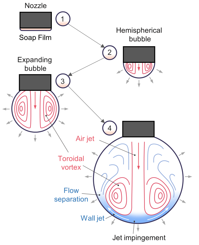
In the current exposition, we consider inflating a soap bubble by expanding a soap film deposited at the tube end opening with air. The first part of the study looks into the dynamics associated with the soap film motion and uses first principles to deduce the scaling laws for the bubble growth rate. The second part delves further into the internal airflow dynamics within this growing bubble. The incoming airflow conforms into a toroidal vortex initially. Eventually, as the bubble grows, air enters as a round jet which impinges on the concave bubble surface, forming a wall jet that eventually separates to form a localized toroidal vortical structure (See Fig. 2, 3 and supplemental movies 1-6).
Experiments: The schematic of the experimental setup is depicted in Fig. 1a. Air supply at a constant pressure from the reservoir is utilised for bubble inflation, where the downstream pressure is controlled using a pressure regulator. A seeder arrangement in line with the flow circuit introduces olive oil droplets of size , which is essential for internal airflow visualisation during bubble blowing. A manometric gauge is used for pressure measurement between the regulator and the seeder. Through valve ’1’ and PU tubes, the output of this apparatus is connected to an acrylic nozzle at the other end having inner and outer diameters of and , respectively. To generate a soap bubble, the nozzle is dipped in a soap solution (Commercial - Bubble Magic) to deposit a soap film at the opening. For repeatability, the nozzle tip is dipped to approximately the same depth of for each run, and the nozzle end is held within a large acrylic enclosure. Valve ’2’ is closed, and valve ’1’ is opened during the inflation process, where the input pressure is pre-adjusted through the regulator. To measure the actual stagnation pressure just after the regulator, valve ’1’ is closed, and valve ’2’ is opened after every run. The pressure measured through the manometer is then considered an equivalent source supply pressure for the system. The air-liquid surface tension of the soap solution was measured using the pendant droplet method, and viscosity was determined using an Anton Paar model rheometer.
The flow visualisation is achieved using a high-speed dual pulsed Nd:YLF laser (pulse energy of 30 mJ, emission wavelength 527 nm, Photonics Inc.), where a laser sheet from a cylindrical lens is passed through the symmetry axis of the bubble and tube system. The images of the illuminated seeded particles for particle image velocimetry (PIV) were captured at 95 frames per second, using a high-speed camera (Photron Mini UX) at a pixel resolution of pixels with a field of view of . The outlines of the bubble interfaces in these images (See Fig. 1b) were used to determine the geometrical parameters like height and radius , considering the bubble to be a spherical cap pinned over the outer edge of the nozzle. The associated nomenclature is depicted in Fig. 1c.
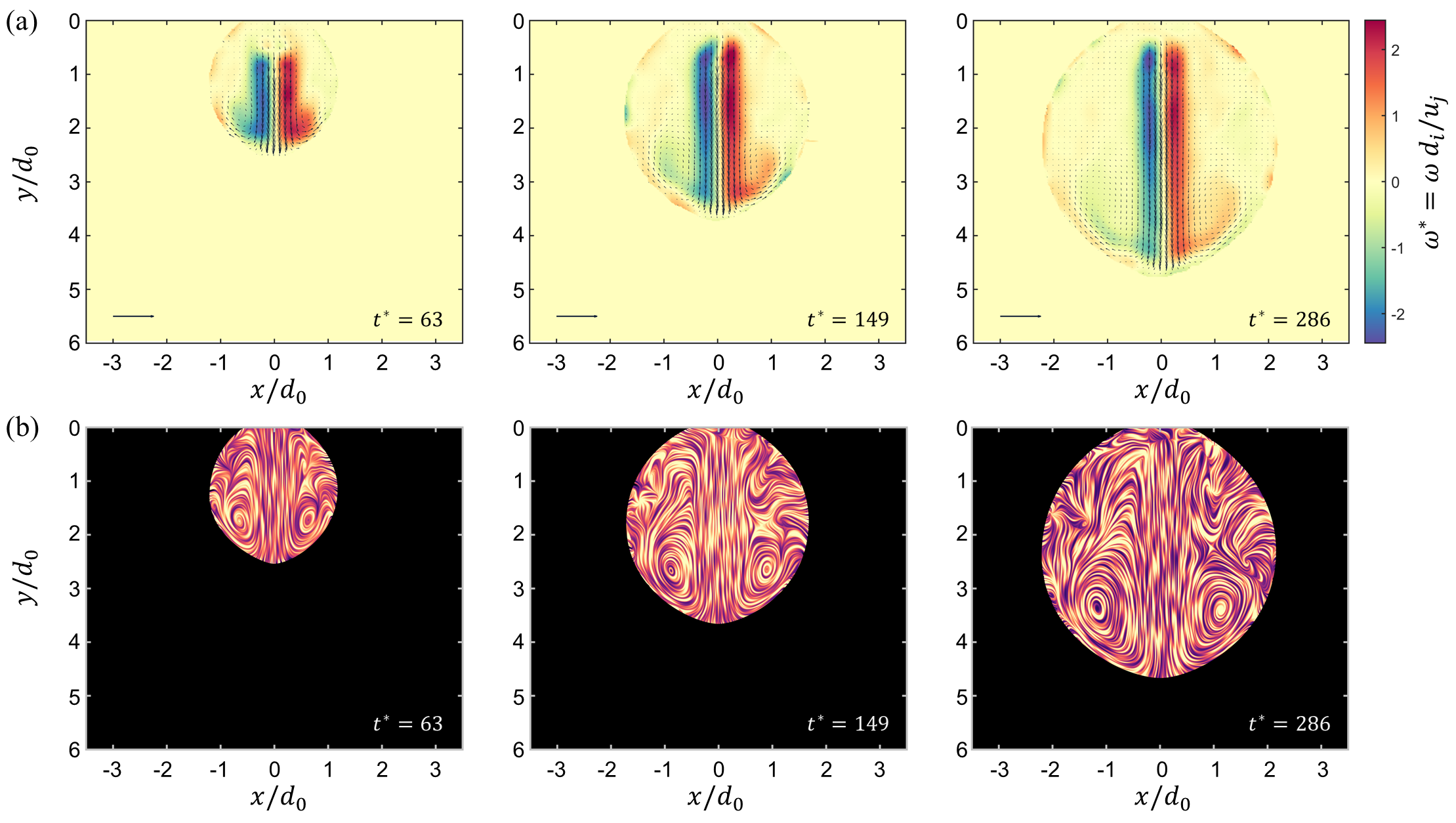
For PIV, the images were post-processed in Davis 8.4 software to obtain the velocity field of the internal flow. This involves a cross-correlation technique with a constant multi-pass interrogation window of size pixels with overlap. The velocity vectors and the vorticity field for a particular source pressure at different normalised time instances are depicted in Fig. 2a (These normalised parameters are defined later). The Line Integral Convolution (LIC) representation [24] depicting streamline-like features in a continuous fashion is illustrated in Fig. 2b. Two counter-rotating vortices are clearly visible in Fig. 2, portraying a dominant toroidal vortex engulfed within the bubble. The internal flowfield hence obtained will be utilised to assess the vorticity dynamics.
A phenomenological sequence of events for the inflation process is depicted in Fig. 3. Bubble inflation is achieved from the tube end with a soap film deposited at the opening. Initially, the incoming air fills the bubble volume, and the flow conforms to the concave confinement within the expanding film. The bubble is eventually hemispherical with a minimum radius of curvature and grows in radius later with further inflation. The internal flow forms a toroidal vortex, which spans the small bubble volume initially. Later, as the bubble grows, the incoming air assumes a round jet form. This laminar jet impinges the soap film at the other end of the bubble, forming a wall jet that moves along the curved inner surface of the bubble. This wall jet eventually separates to form a toroidal vortical structure engulfed within a growing bubble.
Inflation Dynamics: To emulate bubble inflation, a simple model based on Bernoulli’s principle is employed. Applying this between points (A) and (B) (refer Fig. 1a) gives a simple equation for airflow from the source to the bubble as
| (1) |
where is the radius of the bubble considered to be as the spherical cap, is the stagnation gauge pressure at source (measured at (A) in Fig. 1a), is the air density and is the air-soap interface surface tension. The term represents the Laplace pressure and is assumed to be uniform static pressure within the bubble, including the nozzle exit (B) (see Fig. 1a). The average air jet velocity at the nozzle exit can be expressed in terms of the volumetric flow rate and exit area as . is the viscous pressure loss along the pipe and can be expressed as where is the equivalent frictional resistance for the piping system. For a given setup, the experimental parameter should be roughly the same. For a Poiseuille’s pipe flow , where is the air viscosity; and are the effective length and cross-sectional area for the piping system respectively. Eq. 1 can be further simplified to obtain an expression for , which can be equated to the rate of increase in the bubble volume using mass balance. On simplification, the expression for the dimensionless version of the bubble height (See Fig. 1c for bubble and nozzle geometry details) is obtained as
| (2) |
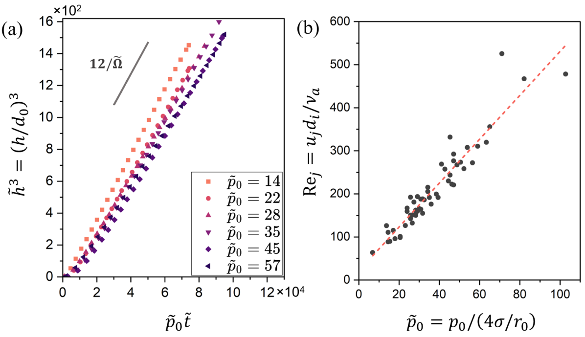
where , with time-scale , and . In the experiments, we observe a linear growth of the bubble volume with time, except for a very short early phase. In the limit of a large bubble , and Eq. 2 approximates to
| (3) |
The experimental data considered in the dimensionless form is hence plotted in Fig. 4a. varies linearly with a modified dimensionless time taking into account the source pressure, as expected from Eq. 3. The curves overlap and the slopes at various pressures assimilate to give a fairly constant , validating our model. Furthermore, as the bubble volume , the slope . The rate of the bubble volume growth was therefore used to evaluate the air jet velocity, which is unsteady only in the early phase of inflation. A steady state is approached as the bubble grows, i.e. the radius increases and the opposing Laplace pressure within the bubble diminishes. Defining the air jet Reynolds number as , from Eq. 3, . The linear correlation is observed in the experimental realisations as depicted in Fig. 4b. From this analysis and experimental observations, we deduce the scaling for the bubble radius with time as for inflation using a constant pressure supply.
Vortical Dynamics: The flow inside the bubble depicts a fascinating toroidal vortex structure as depicted in Fig 2. The vortical flow spans the whole bubble volume and is similar to a Hill’s vortex [25] in the early phase when the bubble is small as depicted in Fig 3. Impingement of the incoming round jet later forms a wall jet at the expanding concave interface, which separates eventually and rolls up to form a vortex localised to the lower part of the bubble as it grows (see Fig 2 and 3). The incoming jet feeds mass to this growing vortex and the bubble as a whole.
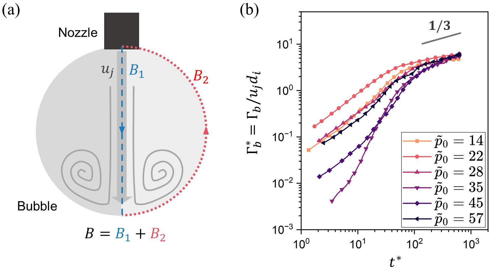
The velocity vector field obtained from PIV is analysed to understand the vortical dynamics associated with the internal flow. The circulation associated with the flow inside the bubble is deduced for the right half within the contour as depicted in Fig. 5a using . The variation of the dimensionless circulation enclosed within bubble with time is depicted in Fig. 5b. We observe the scaling in the later stages of inflation. This can be deduced by dividing the contour into two segments and as depicted in Fig. 5a. Then the circulation can be also expressed as , where it can be shown that and (refer to the Supplemental Material for a detailed discussion). As the height when the bubble is large, this predicts the observed scaling .
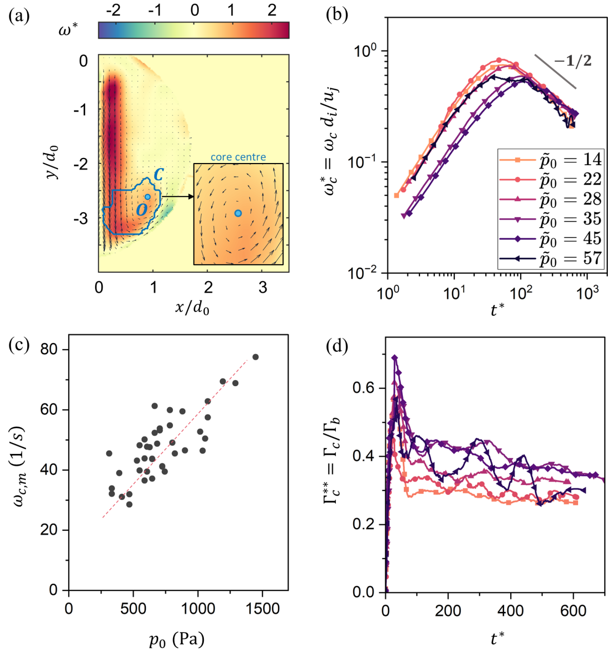
The incoming jet from the nozzle has a dominant shear layer with large vorticity, contributing significantly to the bubble circulation evaluated earlier. In general, a large vorticity value does not necessarily represent a vortex core region [26]. Therefore, the overall bubble circulation may not adequately describe the dynamics associated with the core. The evolution of coherent structures like a vortex core typically governs the interaction dynamics for various flow phenomena including mixing, entrainment, heat transfer, and turbulence. Henceforth, the vortex identification schemes were implemented to isolate the core for further analysis. The criteria [27] was used to identify the location of the prominent core , and the associated core region was determined using swirl strength or criteria [28], as depicted in Fig. 6a. The criteria inspects the relative orientation of velocity vectors in the neighbourhood of a point to identify the core centre, and the criteria determines the core region based on the imaginary part of the eigenvalues of the velocity gradient tensor. A brief discussion of these techniques can be found in the Supplemental material. The core dynamics is assessed through the average vorticity, defined as and circulation . The variation of normalised average core vorticity with time is depicted in Fig. 6b. We observe the scaling . A simple explanation is obtained by scaling vorticity to the velocity gradients where incoming jet velocity serves as a suitable scale along with a characteristic length scale associated with the core such that . The identified core spans the swirling region in the neighbourhood of the core centre (depicted in the inset of Fig. 6a) to the high shear region in the vicinity of the impingement where the jet turns and spreads along the concave soap film. Although from the vector field visualisation, a vortical structure is not apparent in this impingement region, the eigenvalues of velocity gradient tensor (from -criteria), however, predict a dominant rotational component. This unsteady stagnation point flow and the overall recirculatory flow associated with the wall jet separation contribute to core dynamics. Essentially, the wall jet feeds this vortex, and hence, the viscous length scale is suitable to characterise the vortical dynamics of the core [29, 30]. Therefore, , which explains the observed scaling and the peak associated with the core vorticity variation (See Fig. 6b,c).
The core circulation is normalised using the bubble circulation such that . The variation is depicted in Fig. 6d, where it is observed that this dimensionless core circulation approaches a constant value with time, which means that the core circulation eventually follows a scaling law similar to the bubble circulation.
In the initial phase of inflation, core vorticity and circulation depict an increasing trend, which may be accounted for considering the flow confinement. This presumably leads to the rotational flow being concentrated in a small volume available within the bubble. Hence, a coupled growth of bubble size and vortical characteristics is observed until a point where the flow starts to separate. After this, the core vorticity starts to decay. Also, the initial phase is unsteady, with the bottom-most point of the bubble accelerating significantly. In the later stages, the jet impingement is relatively steadier. Also, the average core vorticity of this confined vortex depicts a scaling law independent of the bubble growth rate. The core circulation, when normalised with the overall bubble circulation , depicts a variation qualitatively similar to that of a free vortex ring formation [22, 31]. In earlier studies, this ratio approached a value of for free laminar vortex rings, where the total circulation of the half vortex, including the trailing jet, was used for normalisation. This is similar to what is observed in the current study. Thus, in a sense, the bubble-confined unsteady vortex ring under consideration here also retains these universal characteristics associated with the generation of a free laminar vortex ring. Although the primary source of vorticity generation is the boundary layer at the inner tube walls in the former case, and the wall jet on the bubble interface acts as an additional source in the latter. To have a better understanding of the universality of the vortical dynamics, further research is required into the unsteady phase where the wall jet separation starts and sustains.
Furthermore, the jet impingement here differs from the conventional free jet impingement [32, 33] or vortex impingement [34] studies in terms of the confinement imposed by the bubble interface. The consequences include the imposed entrainment and the vortex interacting with the jet itself. The jet eventually becomes unstable as these effects become prominent for a higher Reynolds number jet. This phenomenon is depicted in the Supplemental material.
Conclusion: In closing, we have discussed the dynamics associated with an inflating soap bubble and the associated internal flow, where we deduce several universal scaling laws associated with the bubble growth and the prominent vortex that forms within. The bubble volume is found to grow linearly in time with the bubble height following the scaling . The bubble circulation follows the scaling and the average core vorticity depicts . The phenomenon occurs prominently due to the round jet impingement with the bubble interface and was investigated within the range . The universality extending from a free vortex ring formation, vortical dynamics of the initial phase and the jet instability induced in the later phases are among the compelling observations that are to be examined further.
Acknowledgments: S. J. Rao and S. Jain would like to thank the Prime Minister Research Fellowship (PMRF) for the financial support. S. Basu would like to thank the support from the Pratt and Whitney Chair professorship.
References
- Boys [1959] C. V. Boys, Soap Bubbles, Their Colours and the Forces which Mold Them (Dover Publications, New York, 1959).
- Lalli and Giusti [2023] N. S. Lalli and A. Giusti, Coherence effects on the interference colors of soap films, Journal of Applied Physics 134, 093103 (2023).
- Lhuissier and Villermaux [2009] H. Lhuissier and E. Villermaux, Soap Films Burst Like Flapping Flags, Physical Review Letters 103, 054501 (2009).
- Giomi and Mahadevan [2012] L. Giomi and L. Mahadevan, Minimal surfaces bounded by elastic lines, Proceedings of the Royal Society A: Mathematical, Physical and Engineering Sciences 468, 1851 (2012).
- Korenjak and Humar [2024] Z. Korenjak and M. Humar, Smectic and Soap Bubble Optofluidic Lasers, Physical Review X 14, 011002 (2024).
- Salkin et al. [2016] L. Salkin, A. Schmit, P. Panizza, and L. Courbin, Generating Soap Bubbles by Blowing on Soap Films, Physical Review Letters 116, 077801 (2016).
- Zhou et al. [2017] M. Zhou, M. Li, Z. Chen, J. Han, and D. Liu, Formation of soap bubbles by gas jet, Applied Physics Letters 111, 241604 (2017).
- Hamlett et al. [2021] C. A. E. Hamlett, D. N. Boniface, A. Salonen, E. Rio, C. Perkins, A. Clark, S. Nyugen, and D. J. Fairhurst, Blowing big bubbles, Soft Matter 17, 2404 (2021).
- Ganedi et al. [2018] L. Ganedi, A. U. Oza, M. Shelley, and L. Ristroph, Equilibrium Shapes and Their Stability for Liquid Films in Fast Flows, Physical Review Letters 121, 094501 (2018).
- Grosjean and Lorenceau [2023] M. Grosjean and E. Lorenceau, Unstable growth of bubbles from a constriction, Physical Review Fluids 8, 053602 (2023).
- Vorobieff et al. [1999] P. Vorobieff, M. Rivera, and R. E. Ecke, Soap film flows: Statistics of two-dimensional turbulence, Physics of Fluids 11, 2167 (1999).
- Roushan and Wu [2005] P. Roushan and X. L. Wu, Universal wake structures of Kármán vortex streets in two-dimensional flows, Physics of Fluids 17, 073601 (2005).
- Seychelles et al. [2008] F. Seychelles, Y. Amarouchene, M. Bessafi, and H. Kellay, Thermal Convection and Emergence of Isolated Vortices in Soap Bubbles, Physical Review Letters 100, 144501 (2008).
- Meuel et al. [2013] T. Meuel, Y. L. Xiong, P. Fischer, C. H. Bruneau, M. Bessafi, and H. Kellay, Intensity of vortices: from soap bubbles to hurricanes, Scientific Reports 3, 3455 (2013).
- Ilssar and Gat [2020] D. Ilssar and A. D. Gat, On the inflation and deflation dynamics of liquid-filled, hyperelastic balloons, Journal of Fluids and Structures 94, 102936 (2020).
- Vagner et al. [2021] S. A. Vagner, S. A. Patlazhan, C. A. Serra, and D. Funfschilling, Vortex flow evolution in a growing microdroplet during co-flow in coaxial capillaries, Physics of Fluids 33, 072010 (2021).
- Zimmer et al. [2015] J. Zimmer, G. Chauvin, and M. Stommel, Experimental investigation and numerical simulation of liquid supported stretch blow molding, Polymer Engineering & Science 55, 933 (2015).
- Manfredi et al. [2019] L. Manfredi, E. Capoccia, G. Ciuti, and A. Cuschieri, A Soft Pneumatic Inchworm Double balloon (SPID) for colonoscopy, Scientific Reports 9, 11109 (2019).
- Costello et al. [2021] J. H. Costello, S. P. Colin, J. O. Dabiri, B. J. Gemmell, K. N. Lucas, and K. R. Sutherland, The Hydrodynamics of Jellyfish Swimming, Annual Review of Marine Science 13, 375 (2021).
- Baskaran and Mulleners [2022] M. Baskaran and K. Mulleners, Lagrangian analysis of bio-inspired vortex ring formation, Flow 2, E16 (2022).
- Di Labbio et al. [2018] G. Di Labbio, J. Vétel, and L. Kadem, Material transport in the left ventricle with aortic valve regurgitation, Physical Review Fluids 3, 113101 (2018).
- Gharib et al. [1998] M. Gharib, E. Rambod, and K. Shariff, A universal time scale for vortex ring formation, Journal of Fluid Mechanics 360, 121 (1998).
- Krieg and Mohseni [2021] M. Krieg and K. Mohseni, A new kinematic criterion for vortex ring pinch-off, Physics of Fluids 33, 037120 (2021).
- Cabral and Leedom [1993] B. Cabral and L. C. Leedom, Imaging vector fields using line integral convolution, in Proceedings of the 20th annual conference on Computer graphics and interactive techniques (ACM, Anaheim CA, 1993) pp. 263–270.
- Hill and Henrici [1997] M. J. M. Hill and O. M. F. E. Henrici, VI. On a spherical vortex, Philosophical Transactions of the Royal Society of London. (A.) 185, 213 (1997).
- Jeong and Hussain [1995] J. Jeong and F. Hussain, On the identification of a vortex, Journal of Fluid Mechanics 285, 69 (1995).
- Graftieaux et al. [2001] L. Graftieaux, M. Michard, and N. Grosjean, Combining PIV, POD and vortex identification algorithms for the study of unsteady turbulent swirling flows, Measurement Science and Technology 12, 1422 (2001).
- Zhou et al. [1999] J. Zhou, R. J. Adrian, S. Balachandar, and T. M. Kendall, Mechanisms for generating coherent packets of hairpin vortices in channel flow, Journal of Fluid Mechanics 387, 353 (1999).
- Tung and Ting [1967] C. Tung and L. Ting, Motion and Decay of a Vortex Ring, Physics of Fluids 10, 901 (1967).
- Allen and Chong [2000] J. J. Allen and M. S. Chong, Vortex formation in front of a piston moving through a cylinder, Journal of Fluid Mechanics 416, 1 (2000).
- Rosenfeld et al. [1998] M. Rosenfeld, E. Rambod, and M. Gharib, Circulation and formation number of laminar vortex rings, Journal of Fluid Mechanics 376, 297 (1998).
- Bergthorson et al. [2005] J. M. Bergthorson, K. Sone, T. W. Mattner, P. E. Dimotakis, D. G. Goodwin, and D. I. Meiron, Impinging laminar jets at moderate Reynolds numbers and separation distances, Physical Review E 72, 066307 (2005).
- Aillaud et al. [2017] P. Aillaud, L. Y. M. Gicquel, and F. Duchaine, Investigation of the concave curvature effect for an impinging jet flow, Physical Review Fluids 2, 114608 (2017).
- Ahmed and Erath [2023] T. Ahmed and B. D. Erath, Experimental study of vortex ring impingement on concave hemispherical cavities, Journal of Fluid Mechanics 967, A38 (2023).
Supplemental Material
Abstract: In this section, we deduce the expression for the circulation associated with the flow enclosed within the bubble. We also briefly discuss the vortex core identification schemes implemented in this study, the instability in the jet observed for higher Reynolds numbers and describe the movies provided in the Supplemental Material.
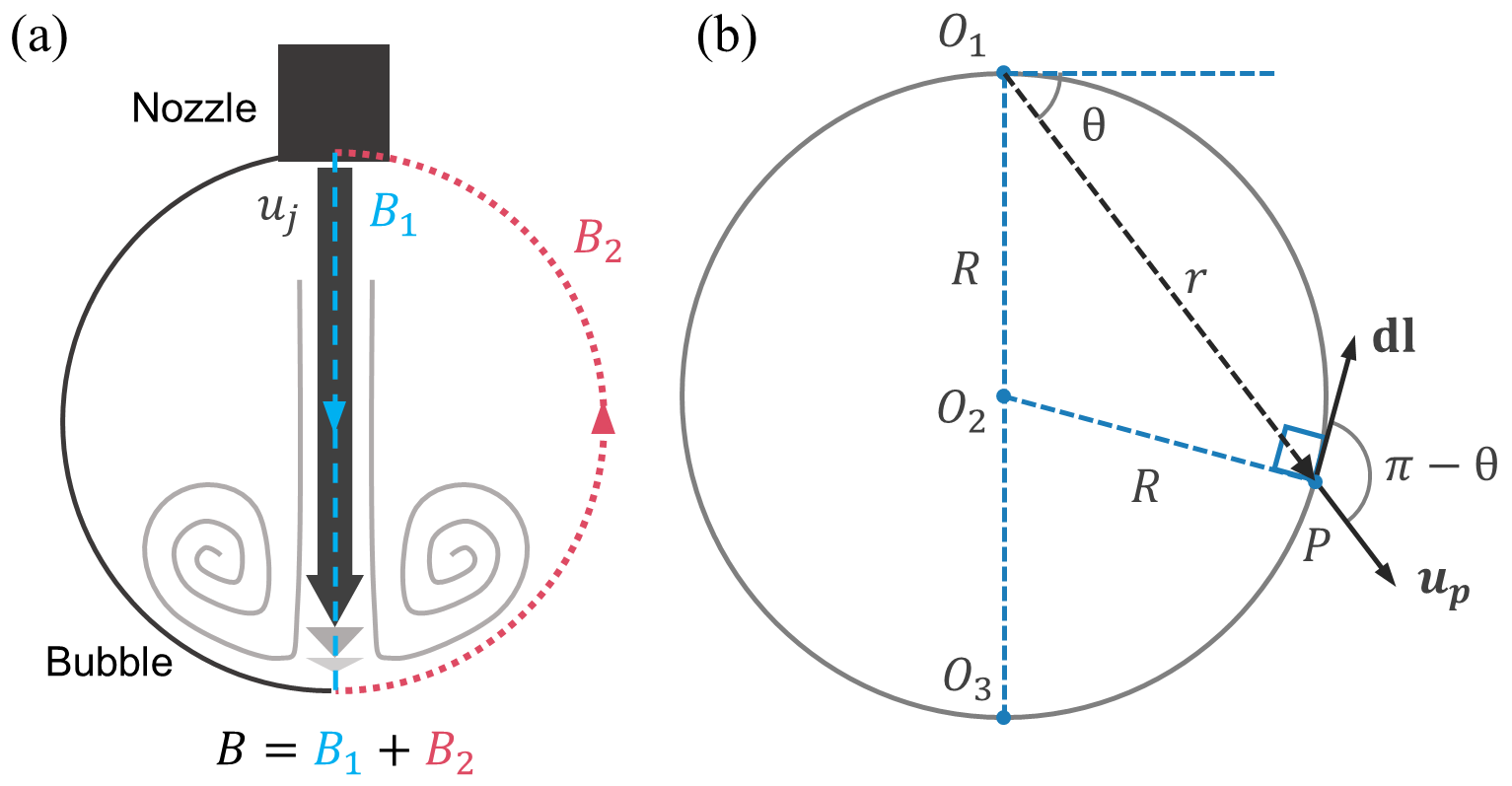
Derivation for Bubble circulation: Here, we deduce the expression for the temporal variation of the bubble circulation. The circulation for the flow inside the bubble is evaluated from experimental data within the contour as depicted in Fig. 7a using . The circulation can also be expressed as
| (4) |
where the contour is segmented into two parts, the diametrical chord aligned with the jet and the semicircle along the bubble interface as depicted in Fig. 7a.
For contribution from , a simple argument can presented that . When the bubble is large, the portion on this segment over which the stagnation occurs at the bottom will be much smaller than the bubble diameter. Hence, we can assume the scaling holds.
For contribution from , we’ll perform the integral along the arc, equivalently the bubble interface as depicted in Fig. 7b. With as the origin, a point on the bubble surface, say , can be expressed in polar coordinates as
| (5) |
where the bubble radius R increases with time and can be expressed as as deduced earlier from the large bubble approximation, where is constant for a given source pressure. Furthermore, the gas phase velocity inside the bubble at the interface should match the boundary velocity. Therefore, the fluid velocity in the radial direction at this arbitrary point (using Eq. 5) is
| (6) |
Substituting this to get along with gives
| (7) |
The relative strength of the circulation contributed from and is hence
| (8) |
where this is essentially the ratio of incoming jet velocity to the bubble interface velocity at the bottommost point. The bubble interface grows slowly when the bubble is large, and hence, for this impingement kind of interaction between the jet and bubble, we have . From Eq. 8, we have . The contribution from is therefore insignificant in the later stages of inflation and hence . As the bubble height in this regime, this predicts the observed scaling .
Vortex core identification schemes: Detecting vortices using vorticity fields may lead to false estimates [26] as they fail to differentiate between shear layers and the desired rotationally dominant regions. In this study, amongst the various available methods, we implement two schemes in conjunction, namely the criteria [27] and the swirl strength or criteria [28] to locate the core within the bubble from the two-dimensional PIV vector field. criteria is a robust method to detect the core centre based on the relative orientations of the velocity vectors within a prescribed neighbourhood of the point under consideration. The parameter is defined as
| (9) |
which is determined at each point in the vector field. PQ denotes the displacement vector from point to inside area in the neighbourhood of containing points, refers to the mean velocity of the fluid enclosed within , refers to the fluid velocity vector at point and z is the unit vector normal to the plane. The peak in the -field corresponds to the core centre location.
The swirl strength criteria [28] determine the vortex or regions with the rotationally dominant flow by considering the eigenvalues of the velocity gradient tensor. The imaginary part of the complex eigenvalue pair is the local swirling strength or . A vortex is then a connected region where the value is positive.
The vortex core of interest in the present study is the connected region identified by the criteria, enclosing the dominant core centre identified using the method (with neighbourhood mm)
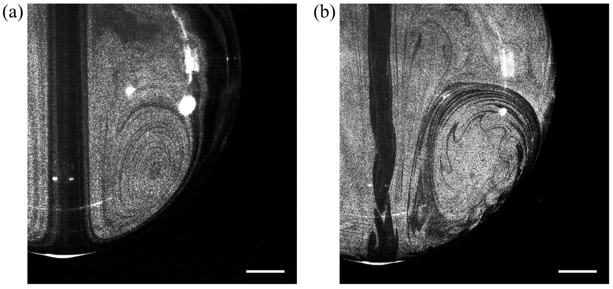
Jet instability: We observed that the bubble inflation displays a round jet feature impinging with the soap film concave interior. The jet impingement within this enclosed confinement includes consequences like forced entrainment and self-interaction with the vortical structure. These effects become prominent as the bubble grows in size for a higher Reynolds number jet and it eventually becomes unstable. The region of interest is shifted downwards to observe this phenomenon, and the captured flow structures are depicted in Fig. 8 for a stable and unstable jet case (see supplemental movies 2-3). In the unstable jet case, i.e. Fig. 8b, we observe small vortical structures embedded within the wall jet and accumulating into the larger coherent vortical structure. The transition is found to happen roughly beyond for the bubble heights within in the current study. Additional investigation is required to comprehend this transition, presumably driven by a feedback mechanism that occurs even within this low Reynolds number regime.
Movie Captions:
-
1.
Visualisation of the internal flow with ROI near the nozzle for the normalised source pressure and jet Reynolds number .
-
2.
Visualisation of the internal airflow during bubble inflation with ROI below the nozzle for the normalised source pressure and jet Reynolds number . A stable jet is observed.
-
3.
Visualisation of the internal airflow during bubble inflation with ROI below the nozzle for the normalised source pressure and jet Reynolds number . An unstable jet is observed.
-
4.
A larger field-of-view visualisation of the internal airflow during bubble inflation for the normalised source pressure and jet Reynolds number .
-
5.
A larger field-of-view visualisation of the internal airflow during bubble inflation for the normalised source pressure and jet Reynolds number .
-
6.
A larger field-of-view visualisation of the internal airflow during bubble inflation for the normalised source pressure and jet Reynolds number .
Note: A planar laser sheet illuminates the airflow seeded with olive oil seeder particles. For scale, the nozzle outer diameter is . Movies 1-3 were recorded with the Photron Mini UX high-speed camera, synchronised with the pulsed laser source. Movies 4-6 were recorded using a Nikon 7200 DSLR camera, where a moving black strip can be observed as the camera was synchronised with the laser. All videos run at actual speed.