Beyond Diagonal RIS for Multi-Band Multi-Cell MIMO Networks: A Practical Frequency-Dependent Model and Performance Analysis
Abstract
This paper delves into the unexplored frequency-dependent characteristics of beyond diagonal reconfigurable intelligent surfaces (BD-RISs). A generalized practical frequency-dependent reflection model is proposed as a fundamental framework for configuring fully-connected and group-connected RISs in a multi-band multi-base station (BS) multiple-input multiple-output (MIMO) network. Leveraging this practical model, multi-objective optimization strategies are formulated to maximize the received power at multiple users connected to different BSs, each operating under a distinct carrier frequency. By relying on matrix theory and exploiting the symmetric structure of the reflection matrices inherent to BD-RISs, closed-form relaxed solutions for the challenging optimization problems are derived. The ideal solutions are then combined with codebook-based approaches to configure the practical capacitance values for the BD-RISs. Simulation results reveal the frequency-dependent behaviors of different RIS architectures and demonstrate the effectiveness of the proposed schemes. Notably, BD-RISs exhibit superior resilience to frequency deviations compared to conventional single-connected RISs. Moreover, the proposed optimization approaches prove effective in enabling the targeted operation of BD-RISs across one or more carrier frequencies. The results also shed light on the potential for harmful interference in the absence of proper synchronization between RISs and adjacent BSs.
Index Terms:
Beyond diagonal reconfigurable intelligent surface (BD-RIS), frequency-dependent RIS, multi-band MIMO networksI Introduction
The run toward the sixth generation (6G) of wireless communication has already started. The relentless quest for seamless coverage, ever-increasing data rates, and high spectral and energy efficiencies is driving the research and development of novel and transformative technologies. In the vanguard of 6G, RIS (RIS) has emerged as a revolutionary paradigm with the promising capability of optimizing the propagation environment, a component over which conventional wireless systems have little or no control. Engineered with a large number of nearly passive reflecting elements with software-tunable electromagnetic properties, an RIS can dynamically adapt and manipulate propagation channels to realize diverse functions, ranging from signal coverage extension and rate maximization to enhanced control of user channel gains and interference mitigation in multi-user scenarios [1, 2].
A conventional RIS can be modeled as a reconfigurable impedance network, where each reflecting element is connected to a single impedance (a reconfigurable self-impedance), which is independent of the other elements. Due to this characteristic, conventional RIS are also called single-connected RIS. One implication of this single-connected RIS architecture is that the induced reflections are traditionally modeled by a diagonal reflection matrix. Recently, as an attempt to improve the reflection efficiency of conventional RIS, the authors of [3] proposed a generalized architecture inspired by multi-port network theory. In this new architecture, each RIS reflecting element, in addition to being connected to its self-impedance, can be also interconnected with the other elements through internal impedances, giving rise to two new BD-RIS (BD-RIS) concepts: fully-connected RIS and group-connected RIS. In a fully-connected RIS, all reflecting elements are interconnected and their induced reflections are now modeled by a full matrix, whereas in a group-connected RIS only sub-groups of the elements are fully-connected but independent across groups, thus, resulting in a block-diagonal reflection matrix. The fully-connected RIS offers the highest reflected power but also counts with the highest circuit complexity. On the other hand, the group-connected RIS provides an intermediate reflection performance, ranging between the performance levels of the conventional single-connected RIS and the fully-connected RIS, but with a lower overall complexity.
In contrast to legacy active radio technologies, both single-connected and BD-RIS architectures require only low-power low-cost components to enable the reconfigurability of their reflecting elements. This attractive characteristic positions RIS as plug-and-play devices with the potential for easy deployment across diverse environments in the future 6G landscape. However, this versatility, while promising, also raises significant concerns. For instance, as we move towards the 6G era, the trend of network densification, characterized by the increasing proximity of BS, is expected to intensify. Additionally, the rising popularity of local networks, combined with the growing necessity of multi-frequency operation, driven by the demanding spectrum requirements forecasted for 6G, should increase the likelihood of multiple BS under multiple bands, controlled by either a single or multiple operators, coexisting within the same spatial location. Assisting such scenarios with RIS may introduce as well serious problems that deserve attention. Specifically:
-
•
Modeling and optimizing RIS without considering their frequency dependency characteristics can result in unexpected effects in practical multi-band environments. This issue may hinder the full potential of RIS technology and lead to degraded communication performance in real-world systems.
-
•
The development of practical configuration strategies for enabling the multi-frequency operation of emerging BD-RIS architectures is another urgent and critical challenge. Frequency-aware optimization schemes for RIS are an absolute necessity to effectively serve users operating under different frequencies in upcoming heterogeneous 6G scenarios.
-
•
Moreover, the unplanned and extensive deployment of RIS in multi-BS networks can cause side effects in the propagation environment that are difficult to tackle at non-intended systems, such as introducing harmful interference against non-targeted users as a result of ineffective channel estimation triggered by RIS-driven active channel aging [4].
While some efforts have been made to address the above points on the single-connected RIS front [5, 6, 7, 8, 9, 10, 11], as of now, they remain unexplored in the context of BD-RIS.
I-A Related Works
A few papers have investigated the practical configuration and frequency response characteristics of single-connected RIS. The work in [5], for instance, studied the phase-amplitude-frequency relationship of reflected signals and introduced a practical reflection model for single-connected RIS considering a point-to-point single-antenna OFDM (OFDM) system. The same frequency-dependent model was later extended to OFDM-aided MIMO (MIMO) systems in [6]. In both works, the authors evaluated the efficacy of the proposed model with its incorporation into the RIS optimization. Simulation results demonstrated that significant performance improvements can be achieved by employing this practical model when compared to the cases with a frequency-blind model in multi-band scenarios. The impact of the frequency-dependency of single-connected RIS in multi-band multi-cell networks was addressed in [7] and [11]. By assuming that each BS operates under a different frequency and adopting a simplified frequency-dependent reflection model, the authors jointly designed the BS precoders and RIS phase-shift matrices aiming at minimizing the total transmit power. Heterogeneous multi-band networks assisted by practical single-connected RIS were studied in [8], where a frequency-aware iterative algorithm was developed to maximize the sum rate of all users under each operating frequency. In [9], the out-of-band performance of a multi-user single-antenna RIS-assisted system was investigated considering a frequency-dependent analytical reflection model, and the work in [10] optimized a single-connected RIS structured into sub-surfaces to assist a multi-frequency MIMO system, where each sub-surface was assigned to a distinct frequency.
Recent studies focusing on diverse aspects of BD-RISs also exist. However, none has investigated their practical frequency-dependent behavior and configuration. For example, the pioneering work on BD-RIS in [3], investigated the scaling law of the received signal power of both fully-connected and group-connect RIS, and showed that the two architectures can significantly improve the power reflection efficiency, remarkably outperforming conventional single-connected RISs. Nevertheless, the influence of frequency was not addressed. In [12], the authors introduced a novel concept of group-connected BD-RIS with a dynamic grouping strategy, in which the reflecting elements were adaptively divided into subsets based on the observed CSI (CSI) of users within a MIMO system. Simulation results demonstrated the performance superiority of the proposed dynamic scheme over static approaches. In [13] and [14], the architecture capabilities of BD-RIS were generalized from only reflective to transmissive and hybrid modes, where double-sided or multi-sector BD-RIS can operate reflecting, transmitting, or executing both functions simultaneously. The work in [15] proposed a new BD-RIS design, in which the reflecting elements were interconnected via switch arrays. The architecture exhibited a lower optimization complexity than that imposed by fully and group-connected RISs. Moreover, in the presented results, the proposed switch-based RIS outperformed the group-connected RIS and approached the performance of the fully-connected RIS counterpart. The combination of BD-RIS with RSMA (RSMA) was considered in [16] and [17]. The authors of [16], specifically, developed a general optimization framework to enhance the spectral and energy efficiencies of both fully and group-connected RIS-aided RSMA in a URLLC (URLLC) system, while the work in [17] concentrated on the application of only fully-connected RIS to the downlink of a multi-antenna RSMA scheme. Low-complexity closed-form optimization strategies for BD-RIS were proposed in [18] and [19], and the impact of discrete coefficients on the performance of BD-RIS was studied in [20]. In [21], the SNR (SNR) maximization problem was explored for point-to-point single-antenna and MIMO channels assisted by BD-RIS, and [22] derived the Pareto frontier for the performance-complexity trade-off of different BD-RIS architectures.
I-B Motivation and Contributions
As described in the previous subsection, the performance advantages of BD-RIS have been demonstrated across diverse scenarios and applications. Nevertheless, while a few works on single-connected RIS have taken multi-band frequencies into consideration, existing research on BD-RIS exclusively focuses on ideal frequency-blind reflection models. Addressing this lacuna, this paper extends the results of [3] by investigating for the first time the frequency-dependent behavior of BD-RIS. Further details and the main contributions of this work are summarized as follows:
-
•
Building upon the contributions of [7, 8], which focused only on single-connected RISs, we propose a novel and generalized practical frequency-dependent reflection model applicable for BD-RIS, i.e., fully-connected and group-connected RISs. This practical model is used as our basic framework for configuring the deployed RIS in a multi-band multi-BS MIMO environment.
-
•
We formulate multi-objective strategies to optimize the practical reflecting coefficients of both fully-connected and group-connected RISs for assisting multiple users connected to different multi-antenna BS, with each BS operating under a distinct carrier frequency. To tackle the challenging original optimization problems, we rely on matrix theory and exploit the symmetric structure of the reflection matrix of BD-RIS to derive low-complexity closed-form relaxed solutions. The achieved ideal solutions are combined with a codebook-based strategy to configure the practical capacitance values for the proposed BD-RIS.
-
•
Comprehensive simulation results are provided to investigate the frequency-dependent behavior of different RIS architectures and to validate the effectiveness of the developed practical optimization strategies. For instance, our results show that the operation of BD-RIS under non-intended frequencies inevitably leads to performance degradation. Nevertheless, even under out-of-band operation, BD-RIS show robustness and can still remarkably outperform conventional single-connected RIS counterparts in all tested cases.
-
•
Furthermore, it is demonstrated that the proposed optimization strategies are effective and enable the RISs to target one or more operating frequencies. Our results also show that harmful interference can be generated for adjacent systems if their BSs, i.e., their channel estimation processes, are not synchronized with the RIS configuration. This critical insight highlights the importance of coordination and synchronization when deploying RISs within multi-band networks.
Notation: Bold-faced lower-case letters denote vectors and upper-case represent matrices. The th element of a vector is denoted by , the entry of a matrix by , the submatrix of formed by its rows (columns) from to by . The norm of a vector is denoted by , and the Frobenius norm of a matrix by . The transpose, Hermitian transpose, and inverse of are represented by , , and , respectively, is the identity matrix, is the zero matrix, and represents the Kronecker product. The operator stacks the columns of an matrix into a column vector of length , applies the inverse operation, transforms the lower triangular half of an matrix into a column vector of length , creates a block diagonal matrix from passed matrices, and denotes expectation.

II Frequency-Dependent Model for BD-RISs
In this section, the multi-port-based reflection model for BD-RIS proposed in [3] is generalized for multi-band operation. In particular, we start by explaining the concept of a fully-connected RIS, in which all reflecting elements are interconnected through reconfigurable impedances and, subsequently, the practical model is extended to group-connected RIS, as follows.

II-A Fully-Connected RIS
A fully-connected RIS comprising reflecting elements can be treated as a -port reciprocal network, where the induced reflections can be modeled by a generalized scattering matrix , which is symmetric, i.e., , due to reciprocity, and satisfies , which implies that due to conservation of energy, where the equality is achieved only when the RIS circuits are lossless. For this ideal case, the RIS scattering matrix becomes unitary, i.e., . Under these observations, the RIS scattering matrix can be given by
| (1) |
where is the reference impedance of the transmission medium and is the matrix collecting the reconfigurable impedances. In a fully-connected RIS, the th element port is connected to the ground via its self-impedance , , and connected to the th port with the impedance , , such that , due to reciprocity. This implies that the entries of the scattering matrix can be completely determined by properly tuning reconfigurable impedances, corresponding to either the upper or lower triangular part of . In particular, the self-impedances for each reflecting element can be modeled as a parallel resonant circuit [5, 8], illustrated in Fig. 1. Specifically, through basic circuit analysis, the self-impedance for the th reflecting element can be calculated as
| (2) |
which, as can be seen, is frequency-dependent and can be adjusted by properly tuning the reconfigurable capacitance , where denotes the carrier frequency, and are inner and outer layer inductances of the RIS reflecting element, and is an effective resistance modeling the losses of the corresponding circuit.
On the other hand, the reconfigurable inner impedances in the transmission lines connecting the elements are implemented by a series resonant circuit111Note that our goal in this work is not to propose an optimal hardware architecture but to shed light on the frequency-dependent behavior of BD-RIS. In-depth studies on circuit design for these new architectures are still missing in the literature and go beyond the scope of this paper., also illustrated in Fig. 3, which is the equivalent circuit for a varactor [5]. With this model, the inter-element impedance between ports and can be easily determined as
| (3) |
where is the capacitance that tunes the transfer impedance between ports and , and and are the effective inductance and resistance for the inner transmission lines, respectively.
It is noteworthy that the frequency characteristics of each reflecting element of a fully-connected RIS cannot be analyzed independently, as performed in previous works such as in [5, 6, 7, 8, 9, 10, 11] for conventional single-connected RISs. Instead, the elements should be studied jointly due to their inherent mutual coupling. We plot in Fig. 2 the phase response of a fully-connected RIS to demonstrate this coupled frequency-dependent behavior and the impact of tuning the circuit capacitances in (2) and (3). For illustrative purposes, we consider the simplest case with two connected elements. As a result, the entries of the matrix will be a function of three reconfigurable capacitances, , , and (which is the same as ), and the operating frequency . To visualize this multi-dimensional phase response, Fig. 2 presents sliced colored volumes, in which the different colors represent the observed phase coefficients, whereas the slices within the volumes correspond to different capacitance or frequency values, depending on the subfigure. Specifically, in Fig. 2(a), for a frequency of GHz, we can see that almost the entire phase range can be achieved by properly tuning the capacitances. It also evident that all three capacitances have influence over the three scattering coefficients, , , and (), revealing the coupled behavior of fully-connected RISs. In Fig. 2(b), we fix the inter-element capacitance to pF and investigate the impact of the operating frequency on the phase coefficients. As can be seen, the frequency plays a significant role in the phase of all scattering coefficients. For instance, considering the coefficient , when pF and pF, its phase observed in the frequency slice of GHz falls within the blue spectrum (around ). However, as the frequency exceeds GHz, the coefficient undergoes a rapid phase change, reaching approximately , in the yellow color spectrum, considering the same capacitance values. Similar trends can be observed with the other scattering coefficients. Such a characteristic provides a strong indication that fully-connected RISs may perform sub-optimally when operating under non-designed frequency bands. This reinforces the need for a careful frequency-aware design and analysis of BD-RISs for their effective deployment.
As shown in a number of recent studies, a fully-connected RIS can significantly outperform conventional single-connected RIS counterparts. However, the associated high circuit complexity can be a limiting factor for its practical deployment. This motivates the consideration of alternative lower-complexity group-connected architectures, in which the reflecting elements are only partially connected. The practical frequency-dependent model presented for fully-connected RISs can be straightforwardly applied to group-connected RISs, as explained in the following subsection.
II-B Group-Connected RIS
As anticipated, a tradeoff between complexity and performance can be achieved by considering group-connected RIS architectures [3], where the reflecting elements within individual groups are fully-connected but independent across groups. Consequently, the scattering matrix for a group-connected RIS with elements, organized into groups, has the following block diagonal structure
| (4) |
where is the scattering matrix corresponding to th independent fully-connected group, for , with each group comprising reflecting elements. Moreover, as for the fully-connected case, the practical frequency-dependent entries of each are determined through (1), (2), and (3), thus, satisfying and . As a result, the entries of , for , can be computed by selecting non-redundant impedances. It is noteworthy that the conventional single-connected RIS corresponds to the special case when , whereas the fully-connected RIS is achieved when .

III System Model
We study in this work a multi-BS downlink MIMO network illustrated in Fig. 3, comprising BS, which are represented by the set . We assume that each BS operates under a distinct carrier frequency and that each BS is equipped with transmit antennas. Moreover, there are single-antenna users connected to the th BS, which, in their turn, are organized in the set . Under this multi-band scenario, one BD-RIS, comprising reflecting elements, is deployed to assist the users within the network. To this end, the practical frequency-dependent reflection model introduced in the previous section is adopted throughout this work.
Given that the BSs operate under different frequencies, we assume that users can eliminate the inter-BS interference by employing a proper filtering strategy. This assumption enables the th BS to multiplex users in space through linear precoding based only on the channels observed under frequency . To this end, we adopt in this work a narrow-band222The study of frequency-dependent beyond diagonal RIS architectures on wide-band systems arises as a potential future direction. block-fading channel model, in which the channels remain constant within a given time coherent interval but vary independently across distinct intervals. Moreover, we assume that the direct links between the BSs and users are under deep fading, meaning that the received power propagates dominantly through the reflected BS-RIS-user links. As a result, the signal received by the th user connected to the th BS, , , can be written as
| (5) |
where represents the data symbol intended for the th user, is the corresponding power allocation coefficient, is the total transmit power budget, and is the additive noise experienced at the user device, which follows the Complex Gaussian distribution with zero mean and variance . In addition, is the precoding vector, which is constructed as a zero-forcing precoder, such that
| (6) |
satisfying . The matrix is the base-band RIS scattering matrix explained in Section II, which is as a function of both the operating frequency and the matrix of selected capacitances , whose main diagonal coefficients are associated with (2) and the off-diagonal coefficients with (3). Last, and comprise the complex baseband channel coefficients for the links between the RIS and the th user and the th BS and the RIS, and .
IV RIS Optimization
In this section, we present the optimization strategies for tuning the scattering matrix of multi-band BD-RIS. Our overall objective is to maximize the received power at users subject to the proposed frequency-dependent RIS constraints.
IV-A Frequency-aware optimization for fully-connected RIS
In a scenario where users count with a good signal reception only in the reflected links, the received power can be maximized by matching the channels between all the BSs and the RIS with all the corresponding channels between the RIS and users. However, because the entries of the matrix will assume different values for each frequency , and given that we dispose of a single RIS, our objective cannot be fulfilled optimally in a global sense. Alternatively, we can find a set of capacitances that provides a balance across the multiple frequencies and users. Such a goal can be expressed through the following weighted multi-objective problem:
| (7a) | ||||
| s.t. | (7b) | |||
| (7c) | ||||
where and are the optimization weights associated with the BSs and the corresponding connected users, respectively. Due to the fact that is a function of both and , combined with the matrix constraints (7b) and (7c), problem (7) becomes intractable to solve. Furthermore, we cannot dedicate the practical reflecting elements for more than one operating frequency simultaneously given that all elements are coupled with one another. Such characteristics of fully-connected RISs further complicate the optimization process.
Instead of solving the original problem in (7) directly, we apply a few relaxations to tackle the challenges highlighted above. To this end, we first formulate an alternative optimization strategy that considers the complex baseband version of the channels for all operating frequencies. Then, the achieved relaxed solution is integrated into a codebook-based strategy targeted at a single priority frequency, i.e., due to the frequency constraints of fully-connected RISs, to finally compute the practical reflecting coefficients. This practical configuration approach is explained in the following. First, we disregard the capacitance and frequency-dependent behavior of , and, second, we relax constraint (7b). This simplified version of the problem can be expressed as follows:
| (8a) | ||||
| s.t. | (8b) | |||
| (8c) | ||||
Problem (8) is still challenging to solve due to the matrix constraints (8b) and (8c). Fortunately, by applying a few transformations, we can achieve an equivalent convex version of such a problem, as follows. First, recall that the elements above the main diagonal of will be redundant due to its symmetric structure. This implies that the desired reflection coefficients can be optimized based on a non-redundant reduced-dimension version of . Such a goal can be achieved with the help of Property I and Lemma I, introduced next.
Property I: Let , and represent arbitrary matrices of compatible dimensions. Then, the following Kronecker identity can be applied:
| (9) |
Lemma I: Let be and arbitrary symmetric matrix. Then, the following transformation holds:
| (10) |
where is the duplication matrix of order , which consists of a full column rank sparse matrix that can be uniquely defined by
| (11) |
where is a unit vector of length with its th entry equals to and zeros elsewhere, and is a matrix with in its entries and , and zeros elsewhere, for .
Proof: Please, refer to [23, Definitions 3.2a and 3.2b]. ∎
With the aid of Lemma I and exploiting the Kronecker identity in Property I, we can define
| (12) | ||||
| (13) |
Then, by plugging transformations (12) and (13) into (8), we can obtain a simplified equivalent version of the problem as follows
| (14a) | ||||
| s.t. | (14b) | |||
Problem (14) can be further simplified by exploiting the following lemma.
Proposition I: Let denote a duplication matrix of order , computed through (11), and denote a vector comprising the non-redundant lower triangular half of an arbitrary symmetric matrix , i.e., . Then, by meeting , the constraint is satisfied almost surely.
Proof: Please, refer to Appendix A. ∎
Supported by Proposition I, and defining , we can further relax (14) and achieve
| (15a) | ||||
| s.t. | (15b) | |||
where the alternative constraint in (15b) still satisfies the law of conservation of energy, as demonstrated by Proposition I, which reflects the passive operation of the fully-connected RIS. The problem in (15) is convex and can be solved by exploiting the singular value decomposition (SVD) of the matrix . Specifically, by recalling the SVD, we can write . Then, the solution of (15) can be computed as , which consists of the eigenvector associated with the largest eigenvalue of the transformed stacked matrix . Thus, the relaxed optimal RIS scattering matrix can be computed as , with given in (11). The resulting impedance matrix can be obtained with the aid of Lemma II, presented next.
Lemma II: Given a scattering matrix for a fully-connected RIS, its associated impedance matrix can be calculated as follows:
| (16) |
Proof: Please, refer to Appendix B. ∎
Recall that we are interested in a matrix with practical impedances that can be implemented with the presented RIS architecture. The work in [7], for instance, studied a multi-band scenario assisted by a conventional single-connected RIS and proposed a strategy of dedicating each reflecting coefficient to one distinct frequency. However, optimizing each coefficient individually is not applicable to the fully-connected RIS case considered in this section due to the interconnected elements. As previously explained, this implies that a practical fully-connected frequency-dependent RIS needs to be configured based on a priority frequency . To this end, we propose next a codebook-based strategy for mapping, i.e., approximating, the optimal matrix to the desired practical solution targeted at frequency .
The non-redundant entries of , the symmetric impedance matrix computed based on through Lemma II, can assume infinitely arbitrary values due to the fact that the constraint (7b) has been relaxed. Next, we construct the two codebooks and comprising practical self and inner impedances, and , using (2) and (3), respectively, in which , where is the number of capacitance quantization bits used in the two codebooks. Then, the entry of the desired practical impedance matrix, corresponding to the target frequency , denoted by , is determined as follows
| (17a) | ||||
where , if , and , if .
The proposed practical configuration strategy for the fully-connected RIS is summarized in Algorithm 1. Note that provides a one-to-one mapping between impedances and reconfigurable capacitances , which are sufficient for computing the scattering matrices , through (1)–(3), for the remaining operating frequencies .
IV-B Frequency-aware optimization for group-connected RIS
As explained in Section II, the groups of reflecting elements in a group-connected RIS are independent. This characteristic allows us to assign each group to a distinct operating frequency, a capability that is not possible with a fully-connected RIS. In this subsection, we also propose a two-step strategy, such that in the first step we optimize the reflecting coefficients based on a relaxed problem, and in the second step, we map the relaxed solution to practical frequency-dependent values based on a codebook-based approach. The base-band relaxed optimization problem for the group-connected RIS case can be formulated as follows:
| (18a) | ||||
| s.t. | (18b) | |||
| (18c) | ||||
| (18d) | ||||
where and are the optimization weights defined as in (7). Before we can solve (18), we need to apply a few transformations to overcome the challenging matrix constraints in (18b)–(18d). First, we define
| (19) | ||||
| (20) |
for . Next, by plugging the above definitions into (18), we achieve
| (21a) | ||||
| s.t. | (21b) | |||
| (21c) | ||||
With the help of Property I and Lemma I, we apply the following transformations
| (22) | ||||
| (23) |
and define
| (24) | ||||
| (25) |
where is the duplication matrix introduced in (11). Then, by invoking (22)–(25), and recalling Proposition I, we can achieve the following problem
| (26a) | ||||
| s.t. | (26b) | |||
Next, by exploiting the property that each RIS group is independent, we select priority BSs, such that , to carry out the optimization. This allows us to assign one or more independent RIS groups to assist a distinct BS. To this end, we define , with , and decouple the problem in (26) into independent sub-problems, as follows
| (27a) | ||||
| s.t. | (27b) | |||
where represents the non-redundant RIS coefficient vector for the th priority BS, . The solution for the th problem in (27) can be obtained with the aid of the SVD, similarly as for the problem (15). More specifically, we can decompose and achieve the desired solution by computing . Finally, the relaxed coefficients for each independent RIS group for the th BS can be obtained as , and , for .
Now, we can exploit the achieved relaxed solutions , for , , to determine the desired practical RIS coefficients targeting up to distinct frequencies. This is carried out through the codebook-based strategy explained as follows. We start by selecting the frequencies from corresponding to the priority BSs, denoted as , such that . Then, for each selected frequency, we construct two codebooks and with practical self and inner impedances and , respectively, in which capacitance values is considered in each codebook. Next, the entry of the practical impedance matrix for frequency of the th fully-connected RIS group, represented by , is obtained based on the following criteria
| (28) |
in which , if , and , if , where is the frequency-blind ideal impedance matrix computed with (16) in Lemma II, corresponding to the relaxed matrix associated with the th targeted BS. This multi-band configuration strategy for block-diagonal RISs is presented in Algorithm 2.
The impedance matrix provides a practical way to determine the required reconfigurable capacitance matrix for the th RIS group, which is independent of the operating frequency. The reflection response generated by the th RIS group with will be optimized for frequency . However, such a response might lead to degraded performance for the other frequencies as a result of the frequency-dependent behavior of BD-RISs demonstrated in Section II. After determining with the aid of (28), the full base-band block-diagonal scattering matrix of the group-connected RIS for frequency , can be given by , where the th block is computed through (1)–(3), . Moreover, note that if the number of RIS groups is equal to the number of serving BSs, i.e., if , we can set and become able to configure each group for each operating frequency of the network. Nevertheless, even if this is possible, one can be interested in prioritizing a subset of the frequencies (or a single frequency), where more than one group can be optimized for a common frequency. In particular, we let this flexible on purpose. In our simulation results, we shall test the performance of different group-frequency assignment criteria.
V Simulation Results
In this section, through insightful simulation results, we investigate the impact of different operating frequencies on the performance of the proposed BD-RIS architectures. The effectiveness of the implemented optimization strategies is also demonstrated. Moreover, we shed light on critical interference scenarios that may emerge within multi-band environments, which highlights the importance of coordination between RIS and neighboring users and BSs.
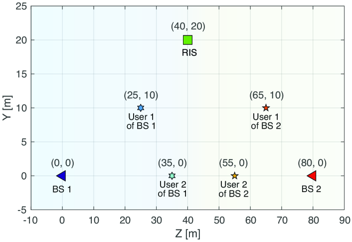
We consider a RIS-assisted multi-band network containing BS, in which BS and are located at the coordinates m and m, respectively, with each BS employing transmit antennas and serving single-antenna users. Specifically, users and connected to the BS are located at m and m, and users and connected to the BS at m and m, respectively. As for the RIS, unless otherwise stated, its location is set to m. The considered simulation setup is illustrated in Fig. 4. With this geometrical scenario, the path-loss coefficients for the links BS-RIS and RIS-U are computed as and , respectively, where and are the corresponding distances, for and , and is the path-loss exponent set to in all links. Regarding the practical RIS configuration strategies in (17) and (28), the number of quantization bits is set to , with the capacitance values uniformly spaced between pF and pF in the generation of all impedance codebooks. In addition, based on values employed in [5], we adjust the remaining fixed RIS circuit parameters in (2) and (3) as , nH, nH, and . For the group-connected RIS cases, we adjust so that each element group can be dedicated to one distinct frequency. The weights for the users in the optimization strategies of Section IV are adjusted as , whereas different values for the weights associated with the BSs are tested in our results. Furthermore, we adjust the noise variance to dBm and employ a uniform power allocation among users, such that , , with a total transmit power set to dBm. Omitted parameters are provided in the simulation examples.
V-A Analysis of the frequency characteristics for different RIS architectures
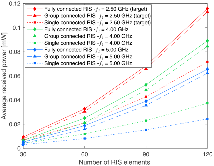
Fig. 5 studies the impact of frequency deviations on the average received power, computed as , versus the number of reflecting elements for different architectures when the practical RIS coefficients are configured considering the target frequency of GHz. To achieve clear insights, we focus on BS and assume that only user is connected in this simulation example. More specifically, the relaxed optimizations in (15) and (26) are executed based on the correct baseband channels. However, the practical configuration of the RIS in (17) and (28) is still carried out (incorrectly) based on the codebook for frequency GHz, e.g, due to a fault in the system. As can be seen, as the operating frequency deviates from the adjusted target frequency, significant performance degradation is caused across all RIS architectures, confirming that frequency indeed plays a crucial role in the reflection efficiency of both conventional single-connected RIS and BD-RIS. Nevertheless, it is clear that single-connected RIS is the most vulnerable, experiencing the strongest decrease in received power when operating outside the target frequency. On the other hand, BD-RIS exhibit remarkable performance superiority even under non-designed operations, revealing their resiliency to undesired frequency shifts compared to the conventional single-connected RIS counterpart.
V-B Assessment of the proposed frequency-aware optimization strategies for BD-RISs in multi-band multi-BS environments
The effectiveness of the practical optimization strategies proposed in Subsections IV-A and IV-B, as well as the adaptability of these schemes for targeting multiple frequencies, is demonstrated in Figs. 6 and 7, where the performance superiority of BD-RIS is again verified. In Fig. 6, the average received sum power per BS, i.e., , for , is presented considering different values for the weights . Specifically, in Fig. 6(a), motivated by the fact that the users connected to BS are further away from the RIS than those of BS , we set a higher weight for BS , i.e., , so that a more balanced performance can be achieved. Following the strategy of [7], we configure the single connected RIS by dedicating half of the elements to frequency GHz and the other half to frequency GHz. As for the group-connected RIS case, we assign each RIS group to one distinct frequency. On the other hand, following the strategy proposed in Subsection IV-A, the relaxed coefficients for the fully-connected RIS are optimized based on the baseband channels of all users of the two BSs. However, because a practical fully-connected RIS can be dedicated to up to one target frequency, its practical coefficients are determined based on the codebook for the frequency GHz. As can be seen in Fig. 6(a), despite this constraint, the fully-connected RIS can still achieve the highest performance under both considered operating frequencies. This result indicates that, at the cost of higher hardware and optimization complexity, a fully-connected RIS is the most robust to multi-user multi-band scenarios among the considered architectures, despite the fact that its practical configuration must be targeted at a single frequency. The group-connected RIS, on the other hand, provides an overall reduced complexity but can still outperform the single-connected RIS counterpart, even though lower gains are achievable. This result is aligned with the findings of [3], confirming that group-connected RISs offer a trade-off between complexity and performance.
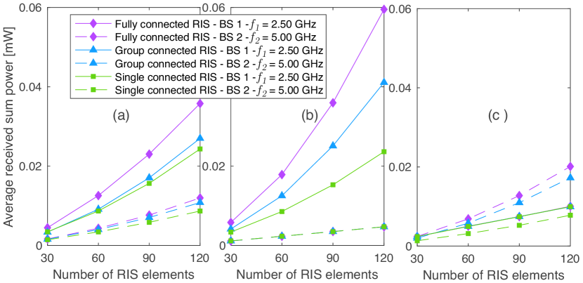
In Fig. 6(b), we set and and optimize the RIS coefficients exclusively for BS operating with GHz, the BS with the strongest users. On the one hand, we can see that the received sum power of users of BS is considerably improved, especially for the BD-RIS cases. On the other hand, low power levels are delivered to the users of BS , with all RIS architectures achieving nearly the same performance. This behavior results from the fact that the RIS operates as it is employing random coefficients for BS since the channels or its connected users are not being taken into account in the optimization, i.e., . We study the opposite scenario in Fig. 6(c), in which, by considering and , we optimize the RISs focused on the BS only, the BS with the weakest users which are being served under GHz. In this case, both fully-connected and group-connected RISs can deliver significant received power gains to the users of BS when compared to the corresponding curves in Figs. 6(a) and 6(b). However, the achieved improvements are not as high as those for BS in Fig. 6(b) due to the higher path losses of the users of BS . Moreover, a significant decline in the sum received power for BS can be observed for all architectures as a result of the random coefficients employed for the users of BS when .
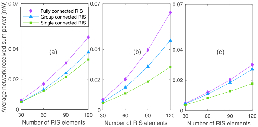
The impact of the choices of tested in Fig. 6 on the overall performance of the network is investigated in Fig. 7, which plots the network average received sum power computed as . In Fig. 7(a), corresponding to the case with balanced weights, each RIS architecture is configured to serve the two BSs simultaneously. As a result, an intermediate network performance is achieved in comparison to the subsequent subfigures. Fig. 7(b), in turn, provides the highest received sum power as a result of the fact that the RIS is dedicated to BS which counts with the closest users. In the other extreme, Fig. 7(c) brings the lowest network sum powers as only BS is being considered in the RIS optimizations. These results show that the overall network performance is highly influenced by the value of , which should be carefully selected based on the requirements and objectives of the system. For instance, if the goal is to maximize network received sum power, the highest weight must be given to the frequency in which the strongest users are operating. If the goal is to assist users connected to different BSs under distinct frequencies instead, balanced weights should be preferred. A final and important insight from Fig. 7 is that the performance advantages of BD-RIS architectures remain also at the general network level for all tested weights.

V-C Analysis of the unplanned deployment of RISs in multi-band multi-BS environments
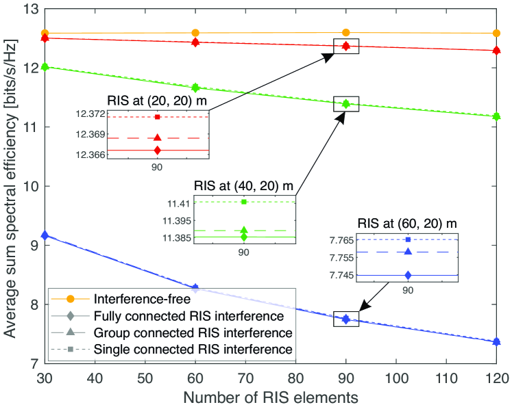
In the previous results of Figs. 6 and 7, we have seen that if an RIS is dedicated entirely to one of the BSs (e.g., and , or vice-versa), the RIS coefficients behave as random for the other BS employing a different frequency. Nonetheless, it can be noticed that, even though the received power for the non-intended BS is degraded, it is still non-zero. This provides a strong indication that if RISs are not properly deployed or well coordinated with neighboring BSs, non-negligible interference can be introduced and degrade multiple access performance. This critical issue is confirmed in Fig. 9, which presents the average sum spectral efficiency for BS , with frequency GHz, under the impact of non-intended reflections induced by an RIS that is optimized exclusively for BS under the target frequency GHz, i.e., and . This investigated interference scenario is illustrated in Fig. 8. For this example, specifically, we assume that the users connected to BS experience a good signal reception in the direct BS-U link and that BS is not aware of the deployment of the RIS. The channel estimate acquired by BS becomes, consequently, outdated due to the unsynchronized operation of the RIS. As a result, the precoders of BS cannot cancel perfectly inter-user interference. Different RIS locations are tested to study the impact of such harmful reflections. As can be seen, even at the coordinate m, where the RIS is relatively far from the users of BS , a noticeable degradation in the sum spectral efficiency curves can be already observed under all three RIS architectures. This performance degradation significantly intensifies as the RIS comes closer to the BS and associated users, resulting in a substantial gap of nearly bits/s/Hz between the sum spectral efficiency achieved by the interference-free system and the case with the RIS comprising elements located at m. Moreover, despite all architectures exhibiting similar performance degradation, when the curves are zoomed in, we can observe that the fully-connected RIS, owing to its superior reflection efficiency, causes slightly stronger degradation, while the single-connected RIS exhibits the mildest impact. These findings highlight the necessity of coordination and synchronization in multi-band multi-BS networks to avoid undesired performance degradation, regardless of the employed architecture.
VI Conclusions
This paper has addressed an important gap in the existing literature on BD-RIS by carrying out a novel investigation into their frequency-dependent behavior. We proposed a new frequency-dependent reflection model applicable for both fully-connected and group-connected RIS, based on which an efficient and practical framework for configuring these promising devices in multi-band multi-BS MIMO environments was developed. Specifically, by relying on a codebook-based approach, integrated with a low-complexity matrix theory-based solution, we implemented flexible multi-objective optimization schemes capable of maximizing the received power at multiple users served under different frequencies. The effectiveness of our strategies was validated through comprehensive simulations across various scenarios. Our results have not only revealed the frequency-dependent performance of different RIS architectures but also demonstrated the superiority of BD-RIS over conventional single-connected RIS counterparts. Furthermore, our findings stress the critical importance of regulating the placement and coordinating the operation of RISs and BSs in multi-band scenarios in order to counter harmful interference. Such measures are crucial to avoid deteriorated performance, emphasizing the need for meticulous planning and optimization for the effective deployment of RIS technology in future 6G.
Appendix A Proof of Proposition I
Note that the product results an augmented vector in which, out of entries of , elements are duplicated (the off-diagonal entries of ), and elements are kept non-redundant (the main diagonal entries of ). This implies that for any , the norm of will always be less than twice the norm of , as a result of the fact that not all of its elements are duplicated by . Mathematically, the following inequality holds
| (A-1) |
With property (A) in hand, and by assuming that , it is guaranteed that
| (A-2) |
The inequality in (A-2) ensures that . As a result, it follows that by constraining , the inequality holds almost surely, which completes the proof. ∎
Appendix B Proof of Lemma II
References
- [1] A. S. de Sena, D. Carrillo, F. Fang, P. H. J. Nardelli, D. B. da Costa, U. S. Dias, Z. Ding, C. B. Papadias, and W. Saad, “What role do intelligent reflecting surfaces play in multi-antenna non-orthogonal multiple access?” IEEE Wireless Commun., vol. 27, no. 5, pp. 24–31, 2020.
- [2] A. S. de Sena, P. H. J. Nardelli, D. B. da Costa, P. Popovski, and C. B. Papadias, “Rate-splitting multiple access and its interplay with intelligent reflecting surfaces,” IEEE Commun. Mag., vol. 60, no. 7, pp. 52–57, 2022.
- [3] S. Shen, B. Clerckx, and R. Murch, “Modeling and architecture design of reconfigurable intelligent surfaces using scattering parameter network analysis,” IEEE Trans. Wireless Commun., vol. 21, no. 2, pp. 1229–1243, 2022.
- [4] H. Huang, Y. Zhang, H. Zhang, Y. Cai, A. Lee Swindlehurst, and Z. Han, “Disco intelligent reflecting surfaces: Active channel aging for fully-passive jamming attacks,” IEEE Trans. Wireless Commun., pp. 1–1, 2023.
- [5] W. Cai, H. Li, M. Li, and Q. Liu, “Practical modeling and beamforming for intelligent reflecting surface aided wideband systems,” IEEE Commun. Lett., vol. 24, no. 7, pp. 1568–1571, 2020.
- [6] H. Li, W. Cai, Y. Liu, M. Li, Q. Liu, and Q. Wu, “Intelligent reflecting surface enhanced wideband MIMO-OFDM communications: From practical model to reflection optimization,” IEEE Trans. Commun., vol. 69, no. 7, pp. 4807–4820, 2021.
- [7] W. Cai, R. Liu, Y. Liu, M. Li, and Q. Liu, “Intelligent reflecting surface assisted multi-cell multi-band wireless networks,” in IEEE Wireless Communications and Networking Conference (WCNC), 2021, pp. 1–6.
- [8] W. Jiang, K. Huang, Y. Chen, X. Sun, J. Yang, and K. Zhao, “A joint design for multi-band heterogeneous networks when deploying reconfigurable intelligent surface,” J. Commun. Networks, vol. 24, no. 5, pp. 613–623, 2022.
- [9] L. Yashvanth and C. R. Murthy, “Does an IRS degrade out-of-band performance?” in In Proc. IEEE International Workshop on Signal Processing Advances in Wireless Communications (SPAWC), 2023, pp. 216–220.
- [10] A. S. Inwood, P. J. Smith, P. A. Martin, and G. K. Woodward, “Phase selection and analysis for multi-frequency multi-user RIS systems employing subsurfaces,” in In Proc. IEEE Wireless Communications and Networking Conference (WCNC), 2023, pp. 1–6.
- [11] W. Cai, R. Liu, M. Li, Y. Liu, Q. Wu, and Q. Liu, “IRS-assisted multicell multiband systems: Practical reflection model and joint beamforming design,” IEEE Trans. Commun., vol. 70, no. 6, pp. 3897–3911, 2022.
- [12] H. Li, S. Shen, and B. Clerckx, “A dynamic grouping strategy for beyond diagonal reconfigurable intelligent surfaces with hybrid transmitting and reflecting mode,” IEEE Trans. Veh. Technol., pp. 1–6, 2023.
- [13] H. Li, S. Shen, and B. Clerckx, “Beyond diagonal reconfigurable intelligent surfaces: A multi-sector mode enabling highly directional full-space wireless coverage,” IEEE J. Sel. Areas Commun., vol. 41, no. 8, pp. 2446–2460, 2023.
- [14] H. Li, S. Shen, and B. Clerckx, “Beyond diagonal reconfigurable intelligent surfaces: From transmitting and reflecting modes to single-, group-, and fully-connected architectures,” IEEE Trans Wireless Commun., vol. 22, no. 4, pp. 2311–2324, 2023.
- [15] Q. Li, M. El-Hajjar, I. Hemadeh, A. Shojaeifard, A. A. M. Mourad, B. Clerckx, and L. Hanzo, “Reconfigurable intelligent surfaces relying on non-diagonal phase shift matrices,” IEEE Trans. Veh. Technol., vol. 71, no. 6, pp. 6367–6383, 2022.
- [16] M. Soleymani, I. Santamaria, E. Jorswieck, and B. Clerckx, “Optimization of rate-splitting multiple access in beyond diagonal RIS-assisted URLLC systems,” IEEE Trans. Wireless Commun., pp. 1–1, 2023.
- [17] T. Fang, Y. Mao, S. Shen, Z. Zhu, and B. Clerckx, “Fully connected reconfigurable intelligent surface aided rate-splitting multiple access for multi-user multi-antenna transmission,” in In Proc. IEEE International Conference on Communications Workshops (ICC Workshops), 2022, pp. 675–680.
- [18] T. Fang and Y. Mao, “A low-complexity beamforming design for beyond-diagonal RIS aided multi-user networks,” IEEE Commun. Lett., pp. 1–1, 2023.
- [19] M. Nerini, S. Shen, and B. Clerckx, “Closed-form global optimization of beyond diagonal reconfigurable intelligent surfaces,” IEEE Trans. Wireless Commun., pp. 1–1, 2023.
- [20] M. Nerini, S. Shen, and B. Clerckx, “Discrete-value group and fully connected architectures for beyond diagonal reconfigurable intelligent surfaces,” IEEE Trans. Veh. Technol., pp. 1–15, 2023.
- [21] I. Santamaria, M. Soleymani, E. Jorswieck, and J. Gutiérrez, “SNR maximization in beyond diagonal RIS-assisted single and multiple antenna links,” IEEE Signal Process Lett., vol. 30, pp. 923–926, 2023.
- [22] M. Nerini and B. Clerckx, “Pareto frontier for the performance-complexity trade-off in beyond diagonal reconfigurable intelligent surfaces,” IEEE Commun. Lett., vol. 27, no. 10, pp. 2842–2846, 2023.
- [23] J. R. Magnus and H. Neudecker, “The elimination matrix: Some lemmas and applications,” SIAM Journal on Algebraic Discrete Methods, vol. 1, no. 4, pp. 422–449, 1980.