Coherent Control of Relativistic Electron Dynamics in Plasma Nanophotonics
Abstract
Femtosecond laser pulses, amplified to ultrahigh intensities, can drive electrons in solids to relativistic energies via collective motion, paving the way for miniaturized particle accelerators and powerful extreme-ultraviolet light sources. However, precisely controlling the space-time properties of these ultra-fast electrons on sub-femtosecond timescales remains a formidable challenge due to the complex nature of interaction at such extreme fields. Here, we present a novel approach to coherently control the local fields on sub-femtosecond timescales at the interface between vacuum and a spatially structured plasma generated from a periodic array of dielectric nanopillars. We experimentally demonstrate and theoretically explain that such control of fields enables enhanced acceleration and steering of relativistic electrons in a desired direction. Furthermore, our simulations predict the coherent formation of sub-femtosecond electron bunches from the nanopillars. Our research brings nanophotonics to the realm of strong-field plasma physics and represents the enabling advancement for in-situ control of high-energy particles, paving the way for novel applications in plasma technology.
1 Introduction
Recent years have witnessed high and ever growing interest in plasma nanophotonics [1] – a field studying the interaction of ultrahigh-power lasers with matter structured at the nanoscale. These extreme interactions have facilitated the creation of ultrahigh-energy-density states [2, 3, 4, 5], exceptionally bright and highly energetic particles [6, 7, 8], tabletop-scale fusion [9, 10], relativistic attosecond electron pulses [11, 12], and extreme ultraviolet (XUV) light sources [13, 14, 15, 16]. Relativistic electrons generated from these interactions [17, 6, 7] are the key to generating extreme states and are crucial for applications. Spatio-temporal control over relativistic electrons is highly desirable, yet extremely difficult to achieve. It requires precise manipulation of local fields on sub-femtosecond (fs) time scales simultaneous with nanometric spatial scales, as these fields strongly influence the trajectories of the electrons. Additionally, precise control is required over plasma parameters.
Despite above challenges, significant progress has been made using two approaches for post-interaction manipulation (upon which electron trajectories are controlled after the generation): either using external electromagnets (magnetic collimation) [18, 19] or specially designed targets [20] with resistivity gradients (resistive collimation) [21, 22, 23]. However, these approaches offer only limited control, primarily affecting the electron beam divergence. A much more attractive approach relies on in-situ manipulation [24, 25], controlling local fields (both laser and plasma field) during the interaction between the fs pulse and the plasma. This allows the guiding or steering of the electron beams directly during their acceleration phase.
In underdense gaseous plasmas, particularly in laser wakefield acceleration (LWFA) [26, 27, 28, 29, 30, 31], in-situ steering of relativistic electron beams has been demonstrated by engineering of incident laser pulses, including manipulating the carrier-envelope phase (CEP) and pulse front tilt (PFT) of the driving few-cycle laser pulse. Such waveform-dependent control of electron beams is however only possible with few-cycle laser pulses ( 10 fs), and it is particularly challenging in laser-solid interactions. Indeed, in solids, the laser pulse interacts with the critical surface of the plasma, where the carrier-envelope phase (CEP) is fixed, while in underdense plasmas, the laser pulse can pass through the plasma (as in LWFA), and the CEP can play a vital role [26].
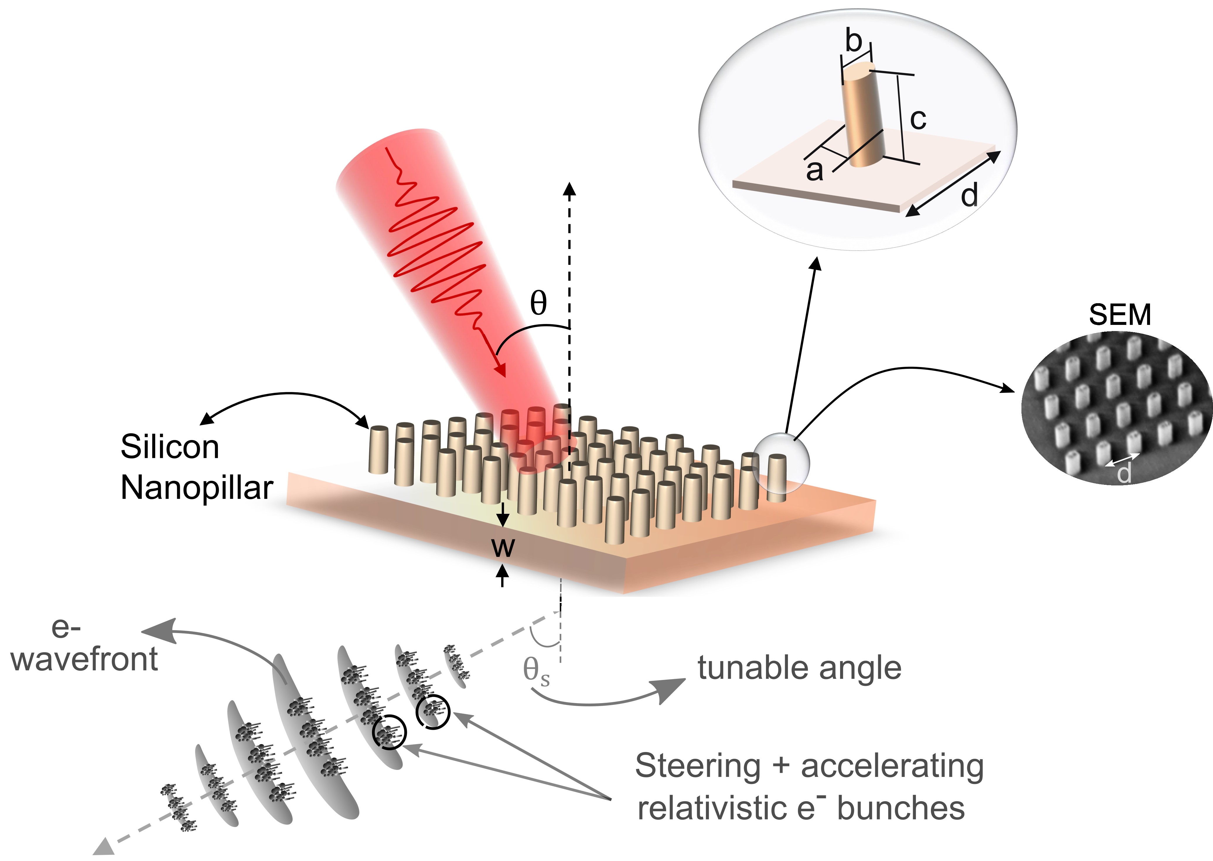
Here, we demonstrate a novel method for in-situ spatio-temporal control of relativistic electrons from laser-solid interactions based on structuring solids on the nanoscale. Our experimental measurements and particle-in-cell (PIC) simulations show both enhanced acceleration and directional steering of relativistic electrons in a desired direction. In our research, we used a periodic arrangement of vertically aligned, near-wavelength-sized nanopillars as the target. The geometry of the nanopillars allows the manipulation of the local near-fields on the vacuum-plasma interface. We exploit the fact that the near-field pattern is due to the interference of the scattered field (Mie scattering) from neighboring nanostructures of the array, which can be controlled either by changing the geometry and arrangement of the nanostructured elements or by controlling the parameters of the driving laser pulse. We show such control on sub-fs time scales and nanometer spatial scales by changing the angle of incidence (AOI) of the excitation laser pulse.


Furthermore, PIC simulations demonstrate that the steered electron beams consist of a train of sub-femtosecond electron pulses. The phase difference of the incident laser between neighboring nanopillars plays a crucial role in controlling the period of these electron pulses. We further observe that electron bunches emitted from different nanopillars are coherently bunched together, in a light-like wavefront structure. Our approach to controlling electron beams is analogous to the working principle of phased array antennas [32], where the manipulation of the relative phase of the driver current between neighboring antennas in the array enables the constructive addition of radiation in a desired direction. We also compare our results both experimentally and via PIC simulations with a flat target and show enhancements in the electron flux and the cutoff energy of the electrons for the nanostructured target.
2 Results
2.1 Experiment
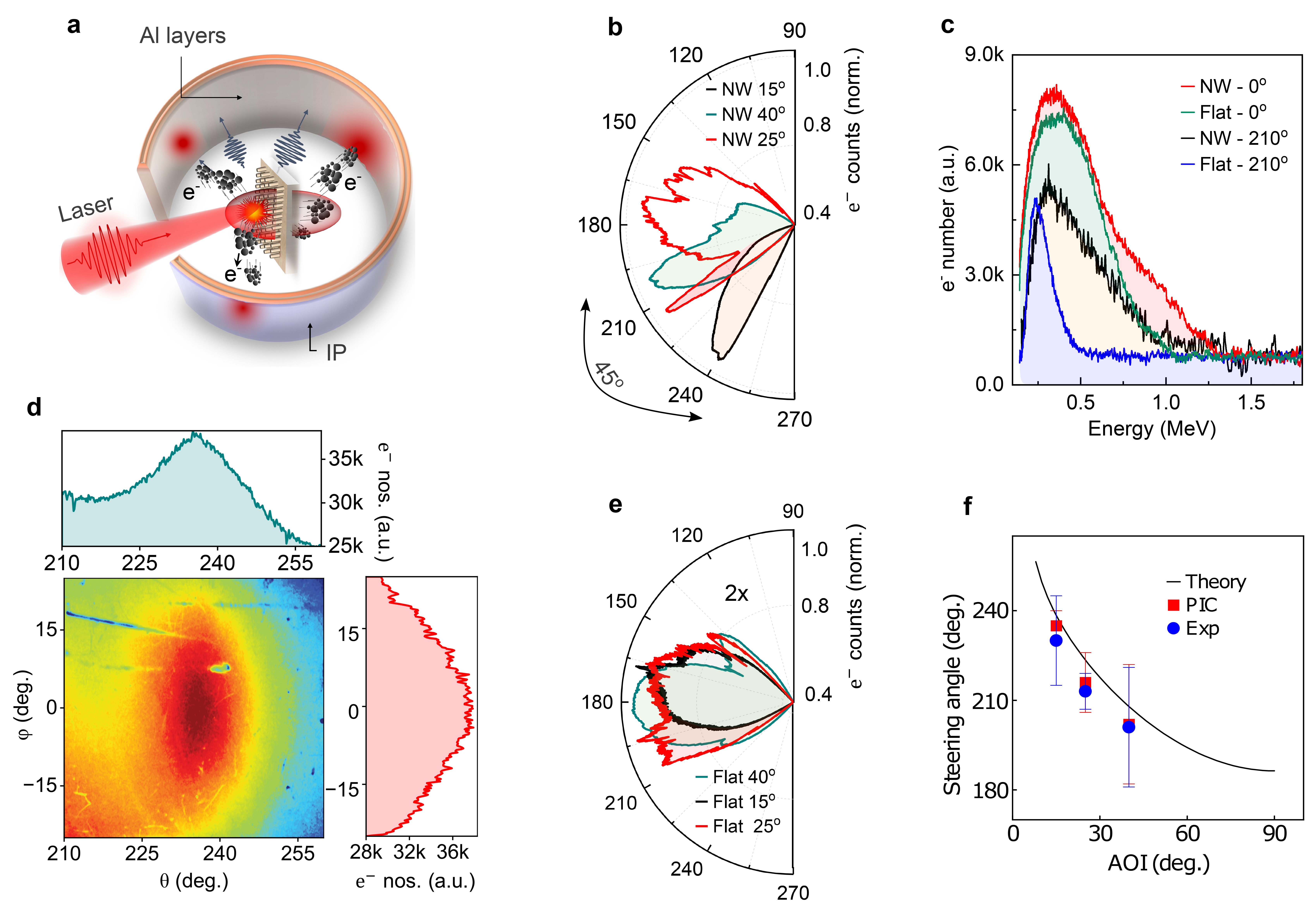
The experiments were performed using p-polarized, 25 fs, 800 nm laser pulses focused to a peak intensity of W/c on a nanostructured target, as depicted in Fig. 1. The nanostructured target consists of a periodic arrangement of perfectly aligned elliptically shaped silicon nanopillars, deposited on a 500-m-thick quartz substrate. For comparison, we also performed experiments on an equally thick (500 m) flat quartz target without nanostructures. See the Methods section for more details on laser parameters and target fabrication. The experimental results for both nanostructured and flat targets are presented in Fig. 2. Fig. 2a shows the schematic of the experimental setup used for measuring the angular distribution of electrons with energy greater than 100 keV (see Methods for more details).
In Fig. 2b, we show the measured angular distribution of rear-side electrons (energy > 100 keV) from the nanostructured target for three angles of incidence (AOIs) of 15°, 25°, and 40°, respectively. It is very interesting to note that for an AOI of 15° and 40°, a significant fraction of electrons in the rear are emitted at a totally different angle than is usually expected, that is, along the target-normal (180°) and along JB (140°-165°) [33]. The emission angle of the electron is closely related to its heating and acceleration mechanisms. Resonance absorption [34] and Brunel heating [35] are associated with near-normal electron emission, while JB heating [36] is attributed to emission along the laser propagation direction. Emission at a significantly different angle in the nanopillar target indicates a different type of acceleration mechanism, discussed later. A more intriguing observation is the steering of the electron beam by simply varying the AOI of the laser pulse. However, for an AOI of 25°, we observe that the guided electrons are significantly less, and more electrons are still along the target normal and JB directions. To investigate this, we repeated the measurement multiple times, which shows that the fraction of steered electrons varies between experiments. This variability is highly dependent on the fabrication quality of the nanostructure and the precise alignment of the laser focal spot on the nanopillars. Notably, for perfectly aligned laser shots, a significant fraction of electrons exhibited directional steering. In Figs. S4 and S3 of the Supplementary Information, we attach the measured angular distribution and the corresponding microscopy images of these laser shots.
For comparison, we show the rear-side electron angular distribution on the flat target in Fig. 2e. In the flat target, the measured rear electron flux is two times less, and most of the electrons are emitted with large divergence along the target normal and along the JB direction, as expected [33]. In Fig. 2d, we show the measured two-dimensional (2D) angular profile of the steered electron beam measured 15 cm from the target, for an AOI of . As evident, the steered electrons have a beam-like profile. Fig. 2c shows the comparison of the energy distribution of electrons from nanostructured and flat targets for an AOI of 40°. The energy spectrum was measured along the front-normal direction (0°) and along the direction of the steered electron beam (210°) in the rear of the targets (see Methods sections for details of the measurement). For the structured target, we observe that rear-side electrons have a cut-off energy as high as 1.2 MeV, which is about two and a half times that for flat target (500 keV). It is also interesting to note that the maximum pondermotive energy [37] that can be gained by electrons near the peak of the laser pulse is around 400 keV; however, it is three times lower than the measured cut-off energy of 1.2 MeV for the structured target. To investigate the enhanced energy gain (acceleration mechanism) and directional steering of relativistic electrons, we performed particle-in-cell (PIC) simulations. A comparison of the experimentally measured steering angle of the electron beam with the results of PIC simulation and a simple theoretical model (presented in the Discussion section) is shown in Fig. 2f.
2.2 Simulations
We performed 2D3V particle-in-cell (PIC) simulations using the EPOCH code [38]. Simulations were conducted using p-polarized, 25 fs, 800 nm laser pulses, with both the laser and target parameters closely matching those used in the experiments. Details of the simulation setup and target parameters are provided in the Methods section. The simulation results for both nanostructured and flat targets are presented in Fig. 3. Panels (a), (b), and (c) are for the nanostructured target, while panels (d), (e), and (f) are for the flat target. Fig. 3a illustrates the z-component of the magnetic field (Bz) and the trajectories of electrons with energies exceeding 200 keV, shown as black dots, at an angle of incidence (AOI) of 40°, captured 30 fs after the laser-plasma interaction. As shown, on the front side of the structured target, represents the reflected laser and a diffraction mode (discussed later); however, on the rear side, exhibits an azimuthal symmetry, akin to a beam-like current of relativistic electrons. The electron beam deviates from the rear-normal by approximately 30° and consists of a train of sub-fs electron pulses, as evident from their trajectories.
In contrast, for the flat target (Fig. 3d) a significant portion of the laser light is reflected, leading to low absorption (only 15, see Fig. S6 of the Supplementary Information). A fraction of the absorbed energy is coupled to the electrons via JxB heating [36], as evident from the electron trajectories. The electrons are injected in the rear side at every half cycle of the laser pulse, along the laser propagation direction (driven by JxB force).
In Fig. 3b, we show electrons (energy > 300 keV) ejected from the nanopillars toward the rear side at the peak of the pump pulse (15 fs). Notably, we observe a train of sub-femtosecond electron bunches emanating from each nanopillar within the FWHM of the pump laser spot. The longitudinal duration of the electron bunches is as small as 500 attoseconds; however, as they propagate farther, they undergo dispersion and become broadened. The bunch length (h) in the transverse direction depends crucially on the parameters of the nanopillars and the acceleration scheme (as discussed later). It is observe that the period of the electron bunches is approximately 2 fs, which is smaller than the period of the driving laser pulse (2.66 fs). Furthermore, the electron bunches are injected into the rearside from the alternate nanopillars (i.e., two injection points at any instant). However, both the period of the electron bunches and the number of injection points vary with the AOI of the pump pulse (see Fig. S10 in Supplementary Information). For comparison, the rear-side electrons (energy > 100 keV) ejected from the flat target are shown in Fig. 3e. We do not observe such attosecond electron bunches, but a large fraction of electrons moving with large beam divergence along the normal and laser propagation directions (JxB). We observe electrons injected into every half-cycle of the laser pulse.
In Fig. 3c, demonstrates the rear-side electron angular distribution for three AOIs of 15°, 25°, and 40°, captured after the interaction of the peak of the laser pulse with the nanopillar target. As shown, a significant fraction of electrons are steered away from the target normal, showing a clear dependence of the steering angle on the AOI of the pump pulse. This is in excellent agreement with the experimental results of Fig. 2b. For comparison, we show the rear-side electron angular distribution on the flat target in Fig. 3f. In the flat target, the electron flux is five times lower, and most of the electrons are emitted along the target normal and a few along the JB direction, as expected, again in very good agreement with the experimental results of Fig. 2e.
Fig. 3g compares the rear-side electron energy spectra for the nanostructured and flat targets at two AOIs: 15° and 40°. For the nanostructured target at 40°, we observe a high-energy cutoff of approximately 1.2 MeV, which aligns remarkably well with the experimental data (Fig. 2c). Similarly, the flat target exhibits a measured cutoff energy of 0.5 MeV, closely agreeing with the simulated value of 0.45 MeV. As shown, the cut-off energy also varies with the AOI of the laser pulse. This can be attributed to the sheath field on the target’s rear; electrons emitted more normally to the target are most deaccelerated compared to the electrons moving at large angles.
3 Discussion
Here, we present a simple theoretical picture to understand the principles behind the acceleration and directional steering of the electron beam. The silicon-nanostructured target used in the study supports two diffraction modes in the far field. One mode is on the front side of the target, as shown in Fig. 3a, while the other is in the transmission direction (on the rear side). The angle of diffraction for the two modes can be calculated using the following formula:
| (1) |
where is the AOI of the laser, and d is the period of the nanopillars in the array. However, it is important to note that the solid nanopillars are ionized at the rising edge of the intense femtosecond laser pulse, creating plasma nanopillars. This overdense plasma does not support the diffraction mode on the rear side of the target (as evident in Fig. 3a). However, surprisingly, we observe that the steered electron beam is directed in the same direction as the diffraction light mode on the rear side, a mode that does not exist for overdense plasma. In Fig. 2f, we compare the expected diffraction angle for the light mode (without plasma, using eq. 1) with the observed angles of the steered electron beam for different AOIs of the laser pulse. This comparison shows a very good agreement and suggests that the periodic plasma nanopillars can steer the electron beams the same way as the grating does to the light beam, satisfying the same grating equation (eq. 1).
To investigate it further, we plot the near-field pattern of the total electric field in Figs. 4c and 4d. The electric field components (shown in c) and (shown in d) arise from both Mie scattering of the incident light by the nanopillars and the sheath field of the plasma. Notably, the field distribution of both and in between nanopillars is very different than that of the incident laser field. We observe that the phase of between nanopillars propagates along the x direction, while the phase of travels along the direction. The relationship holds, where is the same as the steering angle of the electron beam. This is also evident from the fast Fourier transform (FFT) of in the nanowire region, shown in Fig. 4e. As shown, there are two dominant modes: one represents the incident field, and the other is much brighter and along the guiding direction of the electron beam, which is also the same as the angle of diffraction mode in the rear.
We summarize both the acceleration and steering mechanism using the schematic depicted in Fig. 4a and 4b. As shown in Fig. 4a, during the positive half-cycle of the , electrons in the upside nanopillar experience a force in the downward direction. As a result, a bunch of electrons are pulled out of the nanopillar, gaining an initial kinetic energy of around 200 keV. Once ionized, this bunch of electrons experience a quasi-electrostatic force along the direction due to the x component of the electric field (). The potential landscape, = -, experienced by the bunch of electrons due to this force is offset by a phase of 90° to the y-component of the field , as shown in the schematic. The electron bunch is injected near the top of the potential hill, where it gains energy as it travels downhill in the potential landscape. Simultaneously, the phase of travels forward and more electrons are pulled out of the nanopillar and injected in phase with the earlier bunch in the potential landscape, as shown in Fig. 4b. However, dephasing inevitably occurs, leading to the loss of some electrons from earlier bunches as the field travels at the speed of light. This way, the electrons are pulled out throughout the whole length of the nanopillar and accelerated together, which are later injected as sub-fs bunches into the rear side with energy as high as 1.6 MeV. This process repeats with every cycle of the driving laser pulse, resulting in a train of sub-fs electron bunches from each of the nanopillars within the FWHM of the laser spot. The transverse length (h) of these electron bunches significantly exceeds their longitudinal length, as evident in Fig. 3b. This can be attributed to the differential displacement of electrons originating from different regions of the nanopillar: those ionized and accelerated from the tip are subjected to the force in the steering direction for a longer duration, resulting in greater displacement from the nanopillar in the guiding direction compared to their counterparts ejected from the base. To test our theoretical model further, we simulated the steering angle of electron beams for varying nanopillar periods and heights (Fig. S9, Supplementary Information). The results are in excellent agreement with Eq. 1.
Figure 4(f-i), shows how the AOI of the pump pulse can be used to control the phase of excitation. As shown in the schematic of Fig. 4f, when a fs pulse is incident at an angle to the target, because of the tilt of the pulse front with respect to the target surface, different spatial regions of the target are excited at different time delays. This provides a very simple method to control the phase of excitation between the nanopillars of the array. Figure 4g, shows the phase delay experienced by the nanopillars within the FWHM spot of the pump pulse for three different AOIs. We observe that for an AOI of 15°, all the nanopillars are excited with a relative phase difference of less than pi. However, for an AOI of 40°, the neighboring nanopillars of the array are excited with the opposite phase (i.e., delta phi = pi), which results in the injection of sub-fs electron bunches from the alternate nanopillar in comparison to an AOI of 15°, as evident from the scatter plot shown in Figs. 4h and 4i, respectively. The period of the sub-fs electron bunches emitted from each nanopillar depends on the time interval over which the phase of the electric field Ey oscillates between the nanopillars, with the following relation: = cos(), where and are the periods of the electron bunches and laser pulse, and the AOI of the laser pulse.
In conclusion, our research bridges the fields of nanophotonics and strong-field plasma physics, facilitating the spatiotemporal control of relativistic electron beams at such extreme interactions. We demonstrate, both via experiments and simulations, the enhanced acceleration and directional steering of the electron beam in a desired direction. Furthermore, we show the crucial role of the phase of excitations on the sub-fs dynamics of electrons in the nanopillars. This work opens exciting possibilities for manipulating secondary beams like high harmonics and ions in nano-structured plasmas, paving the way for advanced laser-plasma interactions and applications.
4 Methods
4.1 Target fabrication
Normally used fabrication techniques like chemical vapor deposition (CVD) or porous anodic alumina (PAA) templates cannot be used to fabricate the perfectly aligned nanopillars we need. These methods tend to produce random nanorod meshes or undesired clustering, making them unsuitable for our application. Instead, we fabricate our samples from polycrystalline silicon on a quartz substrate using electron-beam lithography. For sample fabrication, we employ a layer of polycrystalline silicon (poly Si) created on a four-inch quartz wafer by using low-pressure chemical vapor deposition (LPCVD) in a horizontal tube furnace. The thickness of the Si film is 850 nm, and the thickness of the substrate is 500 micrometers. The pattern is written using a JEOL 9300FS 100kV electron beam lithography (EBL) tool. Polymethyl methacrylate (950K PMMA A4) is used as a positive tone resist. A 10 nm-thick layer of Cr is evaporated on top of the photoresist to prevent charging during the lithography. After the EBL process, wet chemistry removal of the Cr charge dissipation layer, and sequential development, one more 20 nm-thick Cr layer is e-beam evaporated and lifted off to create a hard mask on top of the poly-Si film. The resulting pattern is translated into the surface by means of anisotropic reactive ion etching (RIE) of the silicon layer, which is not masked by chromium. Finally, the Cr mask is removed by wet etching.
4.2 Experiment
The experiment was conducted using the 150 TW, 25 fs, 800 nm laser system at the Tata Institute of Fundamental Research (TIFR), Mumbai. Laser contrast was measured to be at 25 ps before the peak, and the femtosecond temporal profile of the pump pulse is shown in Fig. S2a of the Supplementary Information. These p-polarized laser pulses were focused on the target using an f/3 off-axis parabolic (OAP) mirror at multiple incidence angles of , and . The measured focal spot of the pump beam was 8 microns, which corresponds to a focused peak intensity of 3× W/c.
An array of silicon elliptical nanopillars arranged in near-wavelength spacing on a 500-micron-thick fused silica substrate was used as the target (shown in Fig. 1). The flat target used for comparison purposes was a 500-micron-thick silicon-fused silica plate.
The angular distributions of electrons were measured with imaging plates (IPs) (FUJI Film, BAS-SR 2025) placed in a cylindrical geometry surrounding the target, covering the angular range from 0 to 360 degrees (see Fig. 2a). The IPs were covered with 110-micron-thick aluminum filters to block electrons with energy below 100 keV and to prevent exposure to X-rays, direct lasers, plasma emissions, and ambient light. The angular distributions for each target and angle of incidence (AOI) were obtained with a single laser shot. The energies of fast electrons were measured using electron spectrometers located along two different directions to the target: the front normal (0°) and along the direction of the steered electron beam (210°) in the rear of the target. Each spectrometer has a 0.1 Tesla magnetic field and an IP as a detector. The measurable range of energies in these spectrometers is 0.1–7.0 MeV. Each electron spectrum was obtained by 15 laser shots. The experiments were performed in a vacuum chamber at a pressure of Torr.
4.3 PIC Simulation
We performed a series of 2D3v particle-in-cell (PIC) simulations in Cartesian geometry using the EPOCH code. The simulation box size is 18 with a cell size of 4nm 5nm and 16/32 macroparticles per cell. The target used in the experiment was modeled as periodically arranged nanopillars (see Fig. 3) with a period of 720 nm and a height of 700 nm. These parameters are consistent with the target used in the experiment. The plasma consists of electrons with an initial temperature of 100 eV and neutralizing ions with a temperature of 10 eV. To reduce the computational cost and avoid numerical heating, most of the simulation runs were performed with a plasma density of 20 . However, we repeated a few runs at 100 to check the precision and convergence of the results. A p-polarized laser pulse with a wavelength of 800 nm irradiates the targets at various incidence angles of 15°, 30°, and 40°. The laser pulse is assumed to be Gaussian in both the longitudinal and transverse directions, with a FWHM pulse duration of 25 fs and a beam waist of 5 m at the focus. The peak intensity of the focused laser is 3× W/c, which is the same as the intensity used in the experiment. The laser reaches the target at t = 0 fs. We ran the simulations for 90 fs, 150 fs, and 200 fs, respectively.
References
- [1] M. F. Ciappina, J. A. Pérez-Hernández, A. S. Landsman, W. A. Okell, S. Zherebtsov, B. Förg, J. Schötz, L. Seiffert, T. Fennel, T. Shaaran, T. Zimmermann, A. Chacón, R. Guichard, A. Zaïr, J. W. G. Tisch, J. P. Marangos, T. Witting, A. Braun, S. A. Maier, L. Roso, M. Krüger, P. Hommelhoff, M. F. Kling, F. Krausz, and M. Lewenstein, “Attosecond physics at the nanoscale,” Reports on Progress in Physics, vol. 80, p. 054401, 5 2017.
- [2] R. Hollinger, S. Wang, Y. Wang, A. Moreau, M. G. Capeluto, H. Song, A. Rockwood, E. Bayarsaikhan, V. Kaymak, A. Pukhov, V. N. Shlyaptsev, and J. J. Rocca, “Extreme ionization of heavy atoms in solid-density plasmas by relativistic second-harmonic laser pulses,” Nature Photonics, vol. 14, pp. 607–611, oct 2020.
- [3] M. A. Purvis, V. N. Shlyaptsev, R. Hollinger, C. Bargsten, A. Pukhov, A. Prieto, Y. Wang, B. M. Luther, L. Yin, S. Wang, and J. J. Rocca, “Relativistic plasma nanophotonics for ultrahigh energy density physics,” Nature Photonics, vol. 7, pp. 796–800, 10 2013.
- [4] C. Bargsten, R. Hollinger, M. G. Capeluto, V. Kaymak, A. Pukhov, S. Wang, A. Rockwood, Y. Wang, D. Keiss, R. Tommasini, R. London, J. Park, M. Busquet, M. Klapisch, V. N. Shlyaptsev, and J. J. Rocca, “Energy penetration into arrays of aligned nanowires irradiated with relativistic intensities: Scaling to terabar pressures,” Science Advances, vol. 3, pp. 3–11, 1 2017.
- [5] V. Kaymak, A. Pukhov, V. N. Shlyaptsev, and J. J. Rocca, “Nanoscale Ultradense Z-Pinch Formation from Laser-Irradiated Nanowire Arrays,” Physical Review Letters, vol. 117, p. 035004, jul 2016.
- [6] A. Moreau, R. Hollinger, C. Calvi, S. Wang, Y. Wang, M. G. Capeluto, A. Rockwood, A. Curtis, S. Kasdorf, V. N. Shlyaptsev, V. Kaymak, A. Pukhov, and J. J. Rocca, “Enhanced electron acceleration in aligned nanowire arrays irradiated at highly relativistic intensities,” Plasma Physics and Controlled Fusion, vol. 62, p. 014013, jan 2020.
- [7] S. Jiang, L. L. Ji, H. Audesirk, K. M. George, J. Snyder, A. Krygier, P. Poole, C. Willis, R. Daskalova, E. Chowdhury, N. S. Lewis, D. W. Schumacher, A. Pukhov, R. R. Freeman, and K. U. Akli, “Microengineering Laser Plasma Interactions at Relativistic Intensities,” Physical Review Letters, vol. 116, p. 085002, feb 2016.
- [8] T. Ceccotti, V. Floquet, A. Sgattoni, A. Bigongiari, O. Klimo, M. Raynaud, C. Riconda, A. Heron, F. Baffigi, L. Labate, L. A. Gizzi, L. Vassura, J. Fuchs, M. Passoni, M. Květon, F. Novotny, M. Possolt, J. Prokůpek, J. Proška, J. Pšikal, L. Štolcová, A. Velyhan, M. Bougeard, P. D’Oliveira, O. Tcherbakoff, F. Réau, P. Martin, and A. Macchi, “Evidence of resonant surface-wave excitation in the relativistic regime through measurements of proton acceleration from grating targets,” Phys. Rev. Lett., vol. 111, p. 185001, Oct 2013.
- [9] A. Curtis, R. Hollinger, C. Calvi, S. Wang, S. Huanyu, Y. Wang, A. Pukhov, V. Kaymak, C. Baumann, J. Tinsley, V. N. Shlyaptsev, and J. J. Rocca, “Ion acceleration and D-D fusion neutron generation in relativistically transparent deuterated nanowire arrays,” Physical Review Research, vol. 3, p. 043181, dec 2021.
- [10] A. Curtis, C. Calvi, J. Tinsley, R. Hollinger, V. Kaymak, A. Pukhov, S. Wang, A. Rockwood, Y. Wang, V. N. Shlyaptsev, and J. J. Rocca, “Micro-scale fusion in dense relativistic nanowire array plasmas,” Nature Communications, vol. 9, p. 1077, mar 2018.
- [11] D. E. Cardenas, T. M. Ostermayr, L. D. Lucchio, L. Hofmann, M. F. Kling, P. Gibbon, J. Schreiber, and L. Veisz, “Sub-cycle dynamics in relativistic nanoplasma acceleration,” Scientific Reports, vol. 9, p. 7321, 5 2019.
- [12] M. Elkind, I. Cohen, D. Blackman, T. Meir, L. Perelmutter, T. Catabi, A. Levanon, S. H. Glenzer, A. V. Arefiev, and I. Pomerantz, “Intense laser interaction with micro-bars,” Scientific Reports, vol. 13, p. 21345, dec 2023.
- [13] R. Hollinger, C. Bargsten, V. N. Shlyaptsev, V. Kaymak, A. Pukhov, M. G. Capeluto, S. Wang, A. Rockwood, Y. Wang, A. Townsend, A. Prieto, P. Stockton, A. Curtis, and J. J. Rocca, “Efficient picosecond x-ray pulse generation from plasmas in the radiation dominated regime,” Optica, vol. 4, p. 1344, nov 2017.
- [14] P. P. Rajeev, P. Taneja, P. Ayyub, A. S. Sandhu, and G. R. Kumar, “Metal nanoplasmas as bright sources of hard x-ray pulses,” Phys. Rev. Lett., vol. 90, p. 115002, Mar 2003.
- [15] S. Mondal, I. Chakraborty, S. Ahmad, D. Carvalho, P. Singh, A. D. Lad, V. Narayanan, P. Ayyub, G. R. Kumar, J. Zheng, and Z. Sheng, “Highly enhanced hard x-ray emission from oriented metal nanorod arrays excited by intense femtosecond laser pulses,” Phys. Rev. B, vol. 83, p. 035408, Jan 2011.
- [16] S. Bagchi, P. P. Kiran, K. Yang, A. M. Rao, M. K. Bhuyan, M. Krishnamurthy, and G. R. Kumar, “Bright, low debris, ultrashort hard x-ray table top source using carbon nanotubes,” Physics of Plasmas, vol. 18, p. 014502, 1 2011.
- [17] G. Chatterjee, P. K. Singh, S. Ahmed, A. P. L. Robinson, A. D. Lad, S. Mondal, V. Narayanan, I. Srivastava, N. Koratkar, J. Pasley, A. K. Sood, and G. R. Kumar, “Macroscopic transport of mega-ampere electron currents in aligned carbon-nanotube arrays,” Phys. Rev. Lett., vol. 108, p. 235005, Jun 2012.
- [18] M. Bailly-Grandvaux, J. J. Santos, C. Bellei, P. Forestier-Colleoni, S. Fujioka, L. Giuffrida, J. J. Honrubia, D. Batani, R. Bouillaud, M. Chevrot, J. E. Cross, R. Crowston, S. Dorard, J.-L. Dubois, M. Ehret, G. Gregori, S. Hulin, S. Kojima, E. Loyez, J.-R. Marquès, A. Morace, P. Nicolaï, M. Roth, S. Sakata, G. Schaumann, F. Serres, J. Servel, V. T. Tikhonchuk, N. Woolsey, and Z. Zhang, “Guiding of relativistic electron beams in dense matter by laser-driven magnetostatic fields,” Nature Communications, vol. 9, p. 102, 1 2018.
- [19] S. Kar, H. Ahmed, R. Prasad, M. Cerchez, S. Brauckmann, B. Aurand, G. Cantono, P. Hadjisolomou, C. L. S. Lewis, A. Macchi, G. Nersisyan, A. P. L. Robinson, A. M. Schroer, M. Swantusch, M. Zepf, O. Willi, and M. Borghesi, “Guided post-acceleration of laser-driven ions by a miniature modular structure,” Nature Communications, vol. 7, p. 10792, 4 2016.
- [20] R. Kodama, Y. Sentoku, Z. L. Chen, G. R. Kumar, S. P. Hatchett, Y. Toyama, T. E. Cowan, R. R. Freeman, J. Fuchs, Y. Izawa, M. H. Key, Y. Kitagawa, K. Kondo, T. Matsuoka, H. Nakamura, M. Nakatsutsumi, P. A. Norreys, T. Norimatsu, R. A. Snavely, R. B. Stephens, M. Tampo, K. A. Tanaka, and T. Yabuuchi, “Plasma devices to guide and collimate a high density of mev electrons,” Nature, vol. 432, pp. 1005–1008, 12 2004.
- [21] B. Ramakrishna, S. Kar, A. P. L. Robinson, D. J. Adams, K. Markey, M. N. Quinn, X. H. Yuan, P. McKenna, K. L. Lancaster, J. S. Green, R. H. H. Scott, P. A. Norreys, J. Schreiber, and M. Zepf, “Laser-Driven Fast Electron Collimation in Targets with Resistivity Boundary,” Physical Review Letters, vol. 105, p. 135001, sep 2010.
- [22] A. P. L. Robinson and M. Sherlock, “Magnetic collimation of fast electrons produced by ultraintense laser irradiation by structuring the target composition,” Physics of Plasmas, vol. 14, 8 2007.
- [23] A. R. Bell and R. J. Kingham, “Resistive collimation of electron beams in laser-produced plasmas,” Physical Review Letters, vol. 91, p. 035003, 7 2003.
- [24] M. Yeung, S. Rykovanov, J. Bierbach, L. Li, E. Eckner, S. Kuschel, A. Woldegeorgis, C. Rödel, A. Sävert, G. G. Paulus, M. Coughlan, B. Dromey, and M. Zepf, “Experimental observation of attosecond control over relativistic electron bunches with two-colour fields,” Nature Photonics, vol. 11, pp. 32–35, 1 2017.
- [25] A. Borot, A. Malvache, X. Chen, A. Jullien, J.-P. Geindre, P. Audebert, G. Mourou, F. Quéré, and R. Lopez-Martens, “Attosecond control of collective electron motion in plasmas,” Nature Physics, vol. 8, pp. 416–421, 5 2012.
- [26] J. Huijts, L. Rovige, I. A. Andriyash, A. Vernier, M. Ouillé, J. Kaur, Z. Cheng, R. Lopez-Martens, and J. Faure, “Waveform control of relativistic electron dynamics in laser-plasma acceleration,” Physical Review X, vol. 12, p. 011036, 2 2022.
- [27] C.-Q. Zhu, J.-G. Wang, Y.-F. Li, J. Feng, D.-Z. Li, Y.-H. He, J. hao Tan, J.-L. Ma, X. Lu, Y.-T. Li, and L.-M. Chen, “Optical steering of electron beam in laser plasma accelerators,” Optics Express, vol. 28, p. 11609, 4 2020.
- [28] J. Vieira, J. T. Mendonça, and F. Quéré, “Optical Control of the Topology of Laser-Plasma Accelerators,” Physical Review Letters, vol. 121, p. 054801, jul 2018.
- [29] Z.-H. He, B. Hou, V. Lebailly, J. Nees, K. Krushelnick, and A. Thomas, “Coherent control of plasma dynamics,” Nature Communications, vol. 6, p. 7156, 5 2015.
- [30] A. Popp, J. Vieira, J. Osterhoff, Z. Major, R. Hörlein, M. Fuchs, R. Weingartner, T. P. Rowlands-Rees, M. Marti, R. A. Fonseca, S. F. Martins, L. O. Silva, S. M. Hooker, F. Krausz, F. Grüner, and S. Karsch, “All-optical steering of laser-wakefield-accelerated electron beams,” Physical Review Letters, vol. 105, p. 215001, 11 2010.
- [31] E. N. Nerush and I. Y. Kostyukov, “Carrier-envelope phase effects in plasma-based electron acceleration with few-cycle laser pulses,” Physical Review Letters, vol. 103, p. 035001, 7 2009.
- [32] C. A. Balanis, Antenna Theory: Analysis and Design. Wiley, 2016.
- [33] B. I. Cho, J. Osterholz, A. C. Bernstein, G. M. Dyer, A. Karmakar, A. Pukhov, and T. Ditmire, “Characterization of two distinct, simultaneous hot electron beams in intense laser-solid interactions,” Physical Review E, vol. 80, p. 055402, nov 2009.
- [34] J. P. Freidberg, R. W. Mitchell, R. L. Morse, and L. I. Rudsinski, “Resonant absorption of laser light by plasma targets*,” Phys. Rev. Lett, vol. 28, p. 795, 1971.
- [35] F. Brunel, “Not-so-resonant, Resonant Absorption,” Physical Review Letters, vol. 59, no. July 1987, pp. 52–55, 1987.
- [36] W. L. Kruer and K. Estabrook, “J×B heating by very intense laser light,” The Physics of Fluids, vol. 28, pp. 430–432, jan 1985.
- [37] P. Mulser and D. Bauer, High Power Laser-Matter Interaction. Springer Tracts in Modern Physics 238, Springer, Berlin Heidelberg, 2010.
- [38] T. D. Arber, K. Bennett, C. S. Brady, A. Lawrence-Douglas, M. G. Ramsay, N. J. Sircombe, P. Gillies, R. G. Evans, H. Schmitz, A. R. Bell, and C. P. Ridgers, “Contemporary particle-in-cell approach to laser-plasma modelling,” Plasma Physics and Controlled Fusion, vol. 57, pp. 1–26, Nov. 2015.
Acknowledgements
GRK acknowledges partial support from J.C. Bose Fellowship grant (JBR/2020/000039) from the Science and Engineering Board (SERB), Government of India. Simulations were performed using EPOCH, which was developed as part of the UK EPSRC grants EP/G054950/1, EP/G056803/1, EP/G055165/1 and EP/ M022463/1. This
work was supported by Australian Research Council (DE210100679) and by a grant provided by the Australian Academy of Science, on behalf of the Department of Industry, Science and Resources under the Australia-India Strategic Research Fund.
The authors acknowledge the TIFR HPC resources used for the simulations reported in this paper.
Author contributions
GRK conceived the idea and supervised the whole study. S.K. designed and fabricated the nanostructured targets. A.D. performed the experiment with help from S.K.R., S.D., A.D.L., and Y.M.V.. A.D. analyzed the data. A.D. performed the PIC numerical simulations. The results and interpretation were discussed and finalized by A.D., S.K., and G.R.K. A.D. wrote the first draft of the manuscript and finalized the manuscript together with S.K. and G.R.K. All authors contributed to the manuscript.
Competing interests
The authors declare no competing interests.
Data availability
The data that support the findings of this study are available from the corresponding author upon reasonable request.
Additional information
Supplementary information is available for this paper. Correspondence and requests for materials should be addressed to A.D. and G.R.K.