Field-free ultrafast magnetization reversal of a nanodevice by a chirped current pulse via spin-orbit torque
Abstract
We investigated the magnetization reversal of a perpendicularly magnetized nanodevice using a chirped current pulse (CCP) via spin-orbit torques (SOT). Our findings demonstrate that both the field-like (FL) and damping-like (DL) components of SOT in CCP can efficiently induce ultrafast magnetization reversal without any symmetry-breaking means. For a wide frequency range of the CCP, the minimal current density obtained is significantly smaller compared to the current density of conventional SOT-reversal. This ultrafast reversal is due to the CCP triggering enhanced energy absorption (emission) of the magnetization from (to) the FL- and DL-components of SOT before (after) crossing over the energy barrier. We also verified the robustness of the CCP-driven magnetization reversal at room temperature. Moreover, this strategy can be extended to switch the magnetic states of perpendicular synthetic antiferromagnetic (SAF) and ferrimagnetic (SFi) nanodevices. Therefore, these studies enrich the basic understanding of field-free SOT-reversal and provide a novel way to realize ultrafast SOT-MRAM devices with various free layer designs: ferromagnetic, SAF, and SFi.
I Introduction
In recent decades, spin transfer torque (STT) has been the primary means of manipulating the magnetic states of ferromagnetic (FM) and antiferromagnetic (AFM) materials using spin-polarized current [1, 2, 3, 4, 5, 6, 7, 8, 9, 10, 11, 12, 13, 14, 15, 16, 17, 18, 19]. However, spin-orbit torque (SOT) has emerged as an efficient alternative means of controlling and manipulating the states of FM/AFM materials using electric current [20, 16, 21, 22, 14]. SOT-switching offers promising advantages over STT-switching, such as high-speed and energy-efficient switching without the need for the switching current to pass through a tunnel barrier, which is necessary for magnetic random access memory (MRAM) [16, 17, 23, 14].
Typically, to obtain SOT-switching, a current is applied in a heavy-metal (HM)/topological insulator(TI) layer on which a FM/AFM free layer is placed [17, 24, 25, 26]. The transverse spin currents generated in the HM/TI layer due to the spin-Hall effect [27] or Rashba effect [25] pass through the free layer positioned on top of the HM layer and induce SOT, consisting of mutually orthogonal field-like (FL) and Slonczewski (damping-like, DL) torques, on the free layer magnetization. However, in most conventional SOT-reversal studies, only the DL-torque component is utilized [28, 24, 29], which results in a high minimal current density required for the desired reversal rate. Additionally, conventional SOT-switching requires an external field or other means (e.g., lateral asymmetric introduced by the thickness variation of layers and an exchange bias field created by antiferromagnetic) to ensure deterministic switching [30, 23, 31]. Recent experimental works have shown that the FL-torque () can be significantly larger than the DL-torque () (i.e., ) in certain nanostructure (e.g.,Ta/CoFeB/Mgo), and the substantial FL-torque can induce magnetization reversal [32, 33, 34, 35, 36, 37, 38]. For dominant FL-torque reversal, a properly designed chirped current pulse, analogous to the chirped magnetic field pulse-induced magnetization switching [39, 40, 41, 42, 43, 44, 45, 46, 47, 48, 49], can be an efficient alternative to drive ultrafast field-free magnetization reversal. However, a recent study [50] proposed a theoretical current pulse based on the constraint of the shortest time, which is difficult to realize practically to obtain the ideal balance of the FL- and DL-torques. Another recent study [51] identified an analytical in-plane current pulse to switch magnetization by balancing the FL- and DL-components of SOT during the switching process. However, the main parameters of this current pulse change with time, making it complex to realize in practice. Therefore, it is still desirable to find a simpler setup with a clear physical mechanism for field-free, fast, and energy-efficient SOT-reversal from the viewpoint of fundamental understanding and applications.
In this study, we investigate magnetization reversal of a perpendicularly magnetized nanodevice by a chirped current pulse (CCP) via SOT. Our findings demonstrate that both FL- and DL-components of SOT in CCP can be efficiently utilized to induce ultrafast magnetization reversal without any symmetry-breaking means. For a wide frequency range of the CCP, the obtained minimal current density is significantly smaller compared to the current density of conventional SOT-reversal and the theoretical limit [50]. This ultrafast reversal is due to the mechanism that the CCP triggers the enhanced energy absorption (emission) of the magnetization from (to) the FL- and DL-components of SOT before (after) crossing over the energy barrier. We also verify the robustness of the CCP-driven magnetization reversal at room temperature. Moreover, this strategy can be extended to switch the magnetic states of perpendicular synthetic antiferromagnetic (SAF) and ferrimagnetic (SFi) nanodevices. Therefore, these studies enrich the basic understanding of field-free SOT-reversal as well as provide a novel way to realize the ultrafast SOT-MRAM device with various free layer designs: ferromagnetic, SAF, and SFi.
II Model and methodology
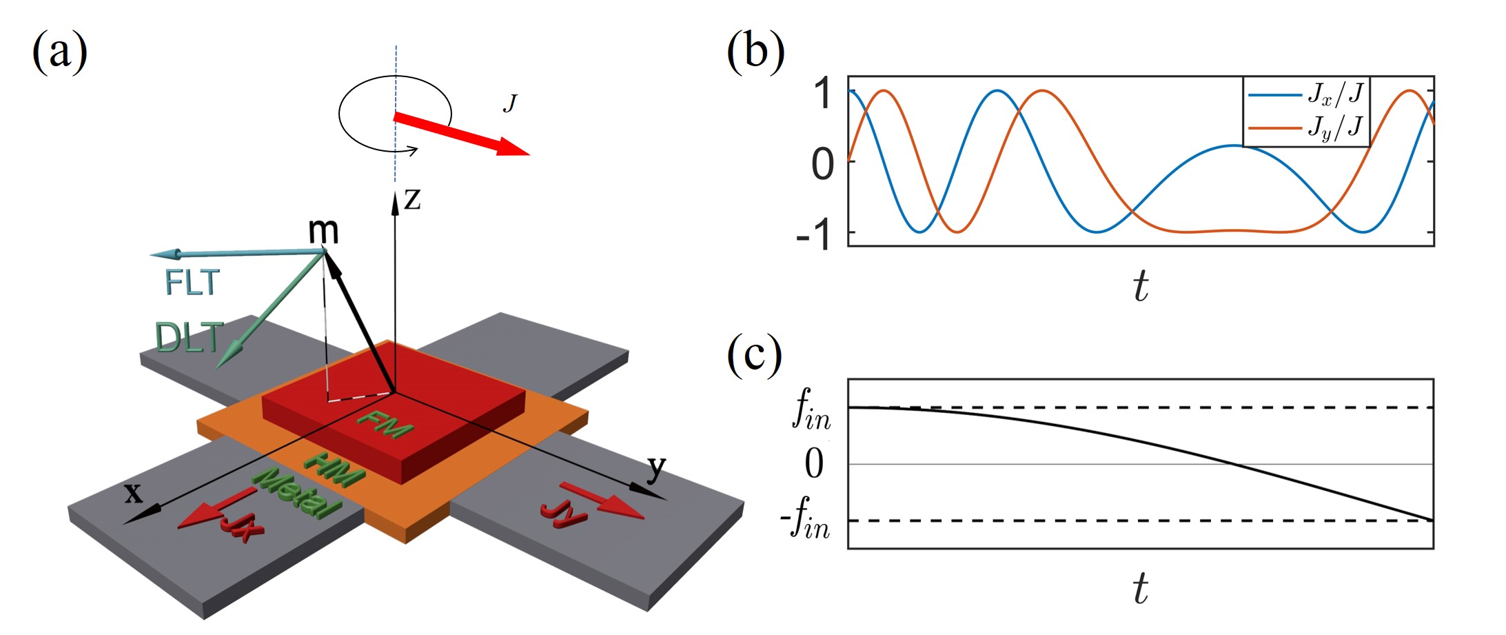
The nanodevice under consideration consists of a ferromagnetic free layer and a heavy metal (HM) layer, as shown in Fig. 1(a). The free layer’s magnetization is perpendicular to the -plane, with two energy minima along the + and - directions due to easy-axis anisotropy. To reverse the magnetization from one stable state to another, a time-dependent rotating electric current pulse is applied, with its two components along the + and + directions in the HM layer. The magnitude of remains constant, and the phase angle between and varies with time. As the current passes through the HM layer, a transverse spin current is generated due to the spin Hall or Rashba effects, which exerts an effective torque on the magnetization [52, 53, 54]. This torque consists of field-like (FL) and damping-like (DL) components, as shown in Fig. 1(a),
| (1) |
and magnitudes (in the unit of magnetic field) of the DL and FL-torques , respectively, is the thickness of the ferromagnetic layer, and are the efficiencies of DL and FL torque respectively. In this study, we use relative strength which is the ratio of the to . is the spin-polarization direction, where is the electric current direction.
In presence of the electric current density, , the magnetization dynamics is described by the explicit Landau-Lifshitz-Gilbert equation [55]
| (2) |
where and are the Gilbert damping constant and gyromagnetic ratio respectively. The effective field comes from the exchange field , and the easy-axis anisotropy field along direction.
From the Eq. (2), it is noted that the DL and FL-torque fields interact with the magnetization in two different means, specifically, the DL torque compels the magnetization along axis while the field from FL-torque generates the precession of magnetization around axis. However, there are the studies [56, 37] which have taken into account the FL-torque as a dominant driving force as in some heavy metal, the FL-torque is significant.
The spin-orbit torque is a non-conservative force which works on the magnetization. Under this non-conservative force, the energy changing rate (with dimension) of the system is presented as (refers to Appendix for detail derivation)
| (3) |
The first term can be zero or negative as it is proportional to , and is always no larger than . This term reflects energy dissipation due to the Gilbert damping. The second term, , can be either positive or negative, contributed by the effective SOT which is generated by the time dependent spin current. Alternatively, the equivalent fields of the FL- and DL-torque can either supply the energy to the magnetization or extract the energy (by negative work done) from the magnetization, depending on the angle between the instantaneous magnetization direction and spin polarization direction [48, 57].
Without any external forces, the easy-axis anisotropy allows the magnetization of the free layer to stay in two equilibrium states/energy minima, and . The main objective of deterministic switching is to move the from one stable state to another. Across the path of switching, requires to climb the energy barrier and cross the equator of energy barrier at and then, because of the Gilbert damping, goes down to another stable state. So the ultrafast and energy efficient reversal might be obtain if the resonantly absorbs energy from external source to reach at the equator and then releases the energy by the negative work-done. In the context of magnetic field driven, such fast and the energy efficient reversal has been demonstrated by the linear down chirped/cosine chirped microwave pulse [48, 57] through the physics of the microwave energy absorption (emission) by (from) the before (after) the equator of energy barrier. To avail the similar mechanism, we employ the CCP (cosine) to utilize FL and DL-torque fields effectively. The CCP can be recast as the form
| (4) |
where is the magnitude of the electric current and is the time-dependent phase angle. is considered as , where (in GHz unit) is the controlling parameter. The frequency of CCP seeps from initial to final with the seeping rate (in units of ) while takes the form . The time- dependent frequency is represented as which is shown in Fig. 1(c). If the pulse duration (time requires to sweep to final ) is , by solving the condition , we get a relation between and as follows,
| (5) |
For this study, we have used the micromagnetic simulation package, MuMax3 [58] to solve the LLG equation numerically. From the viewpoint of experimental realization, we choose the material parameters: saturation magnetization, A/m, perpendicular anisotropy J/m3 or T, rad/T/s, exchange constant J/m, and Gilbert damping = 0.01. The system we focused on has a dimension of nm3, and it was discretized with a mesh size of nm3.
III Numerical Results
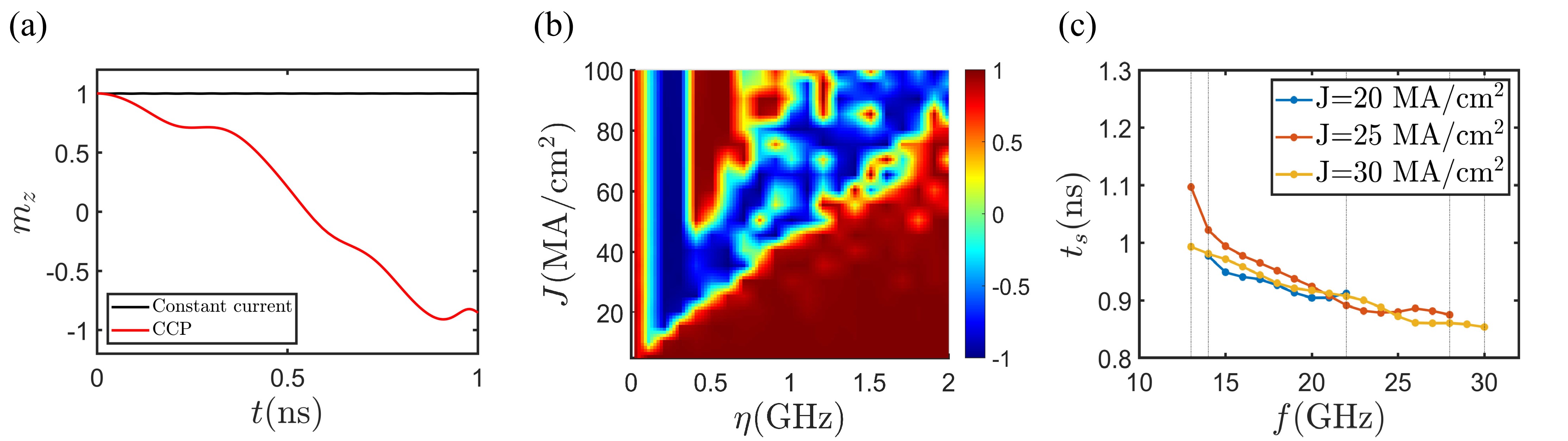
Initially the magnetization stays in one equilibrium state () and its resonant frequency, based on the system configuration and the uniaxial anisotropy (), is determined as GHz. To induce the magnetization switching, we apply the chirped current pulse (CCP) to the heavy metal (HM) layer by choosing the initial frequency of the CCP as GHz so that it closely matches the magnetization precession frequency. Then we investigate the CCP driven switching with different values of the current and . Interestingly, with the minimal MA/cm2 and the optimal 0.22 GHz , the CCP is capable of inducing the fast and efficient deterministic switching (red line) which is shown as in the Fig. 2(a). For fixed GHz and the switching time window 1.5 ns, Fig. 2(b) depicts phase diagram ( ) in terms of and in which blue (red) color indicates the switched, (not switched, ) state. It is found that the critical switching density linearly increases with the increase of . Later on, for different (20, 25 and 30 MA/cm2) of CCP with 0.22 GHz, we investigate the magnetization switching by tuning presented in the Fig. 2(c). It is found, for each current, there is a range of (indicated by vertical lines) around GHz for which the fast reversal is obtained. So, there is a great flexibility of choosing the parameters of the CCP which broadens the path of experimental realization. The pulse width of CCP is ns , refers to the Eq. (5), which is close to switching time 0.94 ns and for deterministic switching, the pulse width does not require to be precised. In addition, this strategy does not require the external field as like the conventional SOT switching which shows the remarkable advantage.
To compare with the conventional switching, we apply 1D current along direction with same magnitude but the does not switch rather it stays in the initial state (black line) as shown in the Fig. 2(a). Then we increase the current and for MA/cm2 (which is ten times larger then the amplitude of the CCP), reverses but its switched back (not shown) i.e., to obtain deterministic switching, the external field is required. To get a better sense about our strategy, we compare the obtained minimal to the theoretical limit of the current density refers to the study [50] and found that the CCP with the minimal MA/cm2, leads the fast switching, which is close to the theoretical limit, MA/cm2 obtained for the same parameters. Although MA/cm2 is required to switch perpendicular magnetization of high anisotropy field T. So it is expected that the minimal would be reduced to the practically feasible range for the material of comparatively lower anisotropy field.
To elucidate the physical mechanism of the CCP driven fast reversal, we express the second term of the (3) in the following form
| (6) |
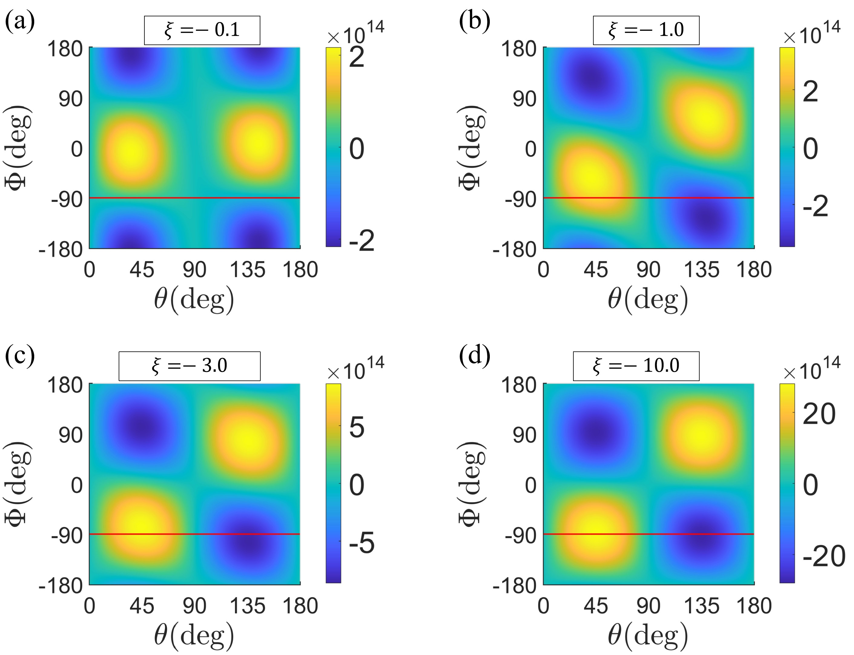
where and are a polar and azimuthal angles of . is the relative phase angle between the in-plane components of and spin polarization direction while is phase angle of . For the fixed material parameters, the rate of energy contribution from SOT components, is found to be dependent on and the . For different values of , we analytically determine the as a function of , varies from 0∘ (initial state) to 180∘ (reversed state) and , varies from -180∘ to 180∘ and thus draw the phase diagrams of in terms of and as shown in the Fig. 3. Particularly, the phase diagrams of for , , and are depicted in Figs. 3(a)-(d) respectively in which the color bars represent the energy changing rate . Yellow and blue colors indicate (energy supplies to by the SOT components) and (energy extracts from by the SOT components) respectively. For the dominant DL-torque, i.e., , yellow color in Fig. 3(a) represents that the energy absorption is occurred at before and after the equator which will not induce the deterministic switching. Then if we include the FL-torque component, that is, for (for equal contribution of SOT components), the energy absorption (emission) would be at smaller (larger) than as indicated by horizontal red line in Fig. 3(b). Of course, it will be difficult to maintain two different before and after the equator. If we further increase the FL-SOT component, i.e., for (dominant FL-torque) as in Fig. 3(c), the maximum energy absorption (emission) before (after) the equator would be occurred at around as indicated by horizontal rel line. So, it is predicted that is required to maintain around -90∘ such that the energy absorption rate, (the energy emission rate) before (after) crossing the equator () becomes maximum which will lead fast and an energy-efficient switching. Finally, for (almost with FL-torque) as in Fig. 3(d), the maximum energy absorption (emission) is occurred at which is similar prediction to the studies of microwave chirped pulse [48, 57].
To understand the mechanism, one can look at the magnetization dynamics under CCP in detail. Fig. 4(a) shows the switching trajectory in which the CCP is switched off at , i.e., just after crossing the equator. goes swiftly from to , after that, changes rotating direction and goes to the ground state slowly as it requires to undergo many turns because of the damping coefficient. However, for the complete CCP, Fig. 4(b) shows the magnetization switching trajectory and found that the rotates anticlockwise (clockwise) before (after) crossing over the equator. Note that, after passing the equator, rotates only a few turns and thus goes to the ground state swiftly. Compare to the former case (CCP is switched off at ), it is evident that, after passing the equator, the CCP extracts the energy from the which leads fast relaxation to the ground sate. Thus, the underlying mechanism is that resonantly absorbs (emits) the energy before (after) crossing the equator from (to) the fields of DL- and FL-torque components.
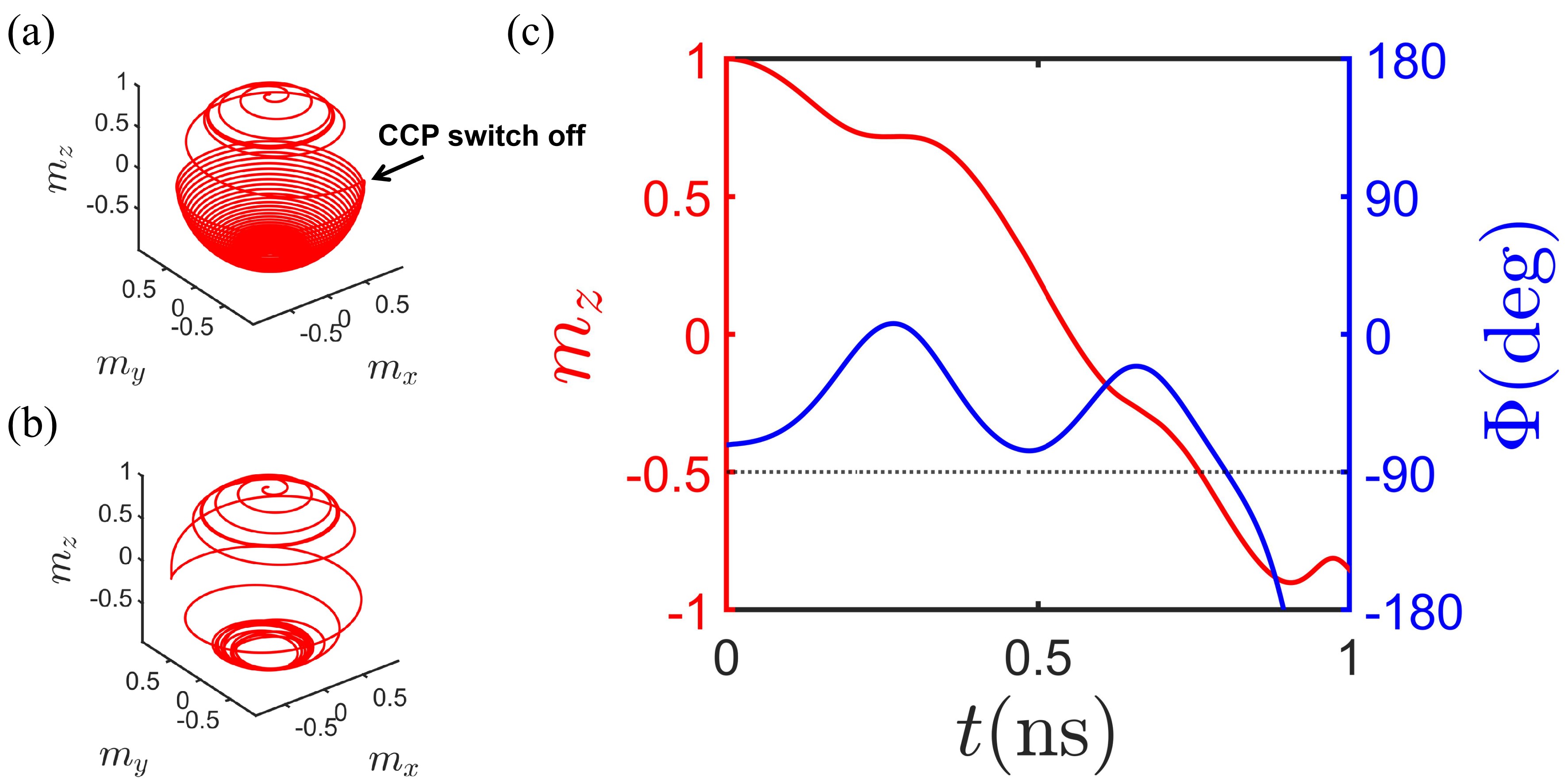
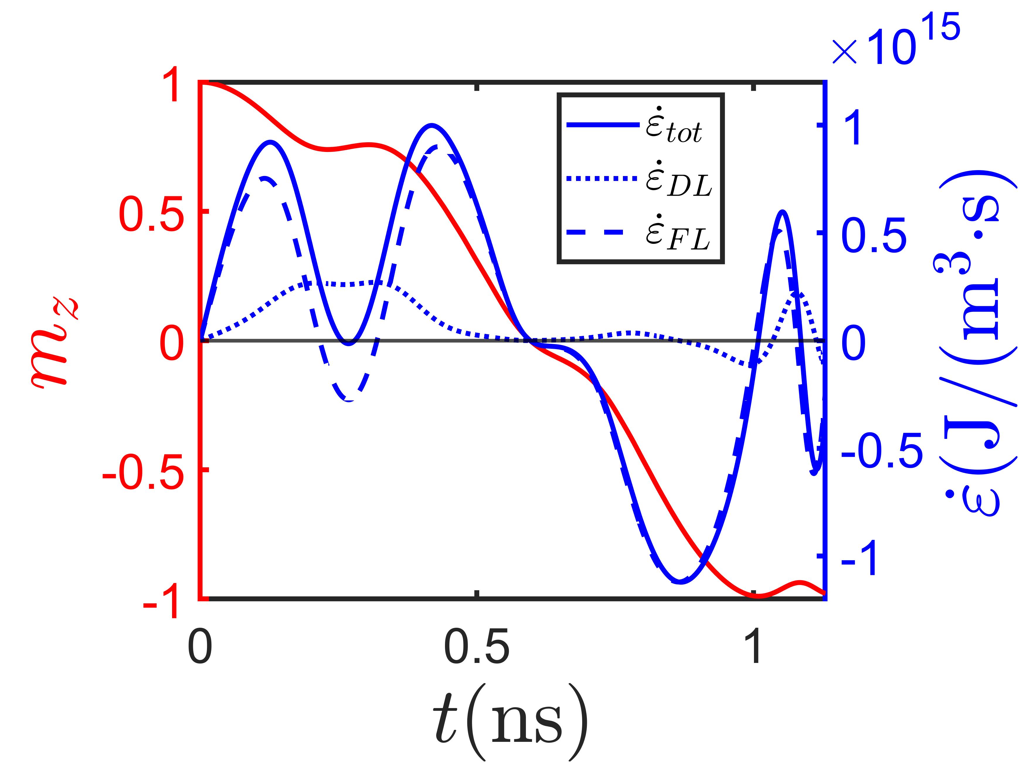
To justify the mechanism, from the simulated data, we determine the azimuthal angles and from the in-plane components of spin current polarization and respectively and thus we estimate the relative phase angle, , between the and which is depicted by the blue line in Fig. 4(c). The red line in Fig. 4(c) represents the transition of from its initial state () to the equator. During this transition, the corresponding is maintained around the range of 0 to -90∘, as shown by the blue line in Fig. 4(c). This behavior aligns with the expected results predicted by equation (6) or Fig. 3(a) for the given scenario. For this time interval, the energy change rates are positive () presented by the dotted blue line (contributed by DL-SOT) and dashed blue line (contributed by FL-SOT) in the Fig. 5. That is, before crossing the equator, both the DL- and FL-torques contributed energy to . After crossing the equator, changes precession direction and similarly the CCP also changes the sense of rotating direction. Consequently, the again maintains around to by balancing the fields of DL- and FL-torque components. In this time interval, is negative shown by the dotted blue line (DL-SOT) and dashed blue line (FL-SOT) in the Fig. 5. That is, the stimulated energy emission is occurred by through the negative work done. The total energy changing with time contributed by the full SOT is shown by solid blue line in Fig. 5. Therefore, efficiently absorbs (emits) the energy before (after) crossing the equator from (to) the fields of DL- and FL-torque components, in other words, the CCP triggers the efficient energy absorption (emission) of the magnetization from (to) the FL- and DL-components of SOT before (after) crossing over the energy barrier.
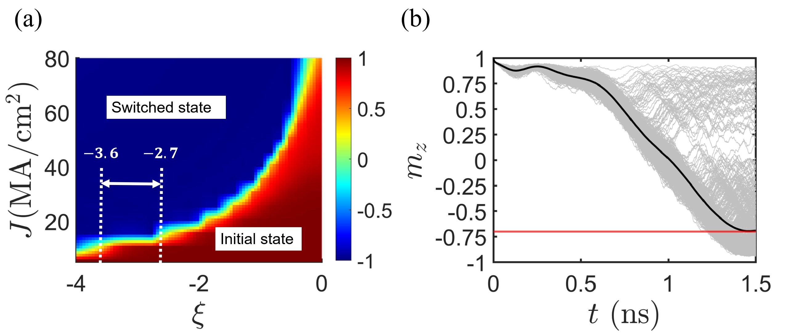
We also investigate the magnetization switching for a range of ) to see how the current density of CCP changes. For fixed = 16.8 GHz, 0.22 GHz and switching time window of 1.5 ns, Fig. 6(a) shows the phase diagram () of magnetization switching in terms of current amplitude J of CCP and with the other parameters kept similar, in which the blue region indicates the switched state and red region indicates the not-switched state (i.e., initial state). It shows that for larger i.e., for the FL-SOT dominated case, smaller J is enough to switch. Note that there is a range of (-3.6 to -2.7) (indicated by the two vertical dot lines) for which the constant current is required. This range of will provide an advantage for device application. However, it is suggested to use as larger value of as possible for an efficient CCP driven switching.
Since the temperature is present everywhere in nature. So, to satisfy the realistic condition, it is meaningful to check the strategy whether the CCP driven magnetization reversal is valid at finite/operating temperature. Purposely, we use the stochastic Landau Lifshitz Gilbert (sLLG) equation to simulate the system with finite temperature and examine the CCP ( with the parameters MA/cm2, and GHz) driven magnetization reversal at 300 K for the same material parameters as before. To find the proper estimation (using the similar approach of the studies [59, 49]), we repeat 1000 times (by changing the thermseed) of the CCP driven magnetization switching () for the same material parameters. Then take the ensemble average of as shown in the Fig. 6(b) and thus find that the magnetization switching (bold black line) is valid and robust even at room temperature.
Recently, the reversal of antiferromagnetic (AFM) state draws much attention as the AFM nanostructure possesses some intriguing properties like the ultrafast spin dynamics, insensitivity against external magnetic field, zero stray field [60, 61, 22, 14]. Similar to AFM system, people also focus on magnetization reversal of the synthetic antiferromagnetic (SAF) and synthetic ferrimagnetic (SFi) nanodevice due to their promising properties of zero stray field [62, 63] and high thermal stability [64, 65, 66]. So, it is interesting to check whether the above strategy works efficiently also to reverse the magnetization of SAF and SFi nanodevices. Purposely, the schematic diagrams of SAF and SFi systems are shown in Fig. 7(a) and (b) in which two ferromagnetic layers, coupled through the interlayer exchange interaction of Ruderman–Kittel–Kasuya–Yoshida (RKKY) [22], mediated by a sandwiched heavy metal layer. For SAF, the upper and lower layer have same dimension ( nm3) and same material parameters as previously chosen for the FM system. We intend to apply the CCP in the sandwiched layer (which is heavy metal) and thus the transverse spin currents, which are generated because of the Spin-Hall effect, pass through the adjacent upper and lower ferromagnetic layers as shown in Fig. 7(a). So both transverse spin current components from the CCP can be utilized efficiently to switch magnetization of upper (up to down) and lower (down to up) layers in opposite directions. The demagnetization field of SAF system is zero, so the resonant frequency is obtained as GHz. Now we investigate the magnetization reversal by applying the CCP with GHz and for different values of and . Interestingly, we found that, the CCP, with 44.98 GHz, the minimal current MA/cm2 and optimal GHz, is capable of driving the field-free ultrafast (around 200 picosecond) magnetization reversal of the both layers. Red line in the Fig. 7(c) shows only the reversal of the upper layer while blue line shows the stimulated energy absorption/emission by/from the magnetization. Note that the behavior of the rate of change of energy absorption/emission of (blue line) before (after) crossing the energy barrier is similar to the FM system (solid blue line in Fig. 5). That is, the mechanism and explanation of the fast reversal of SAF under the CCP is analogous to the FM system.
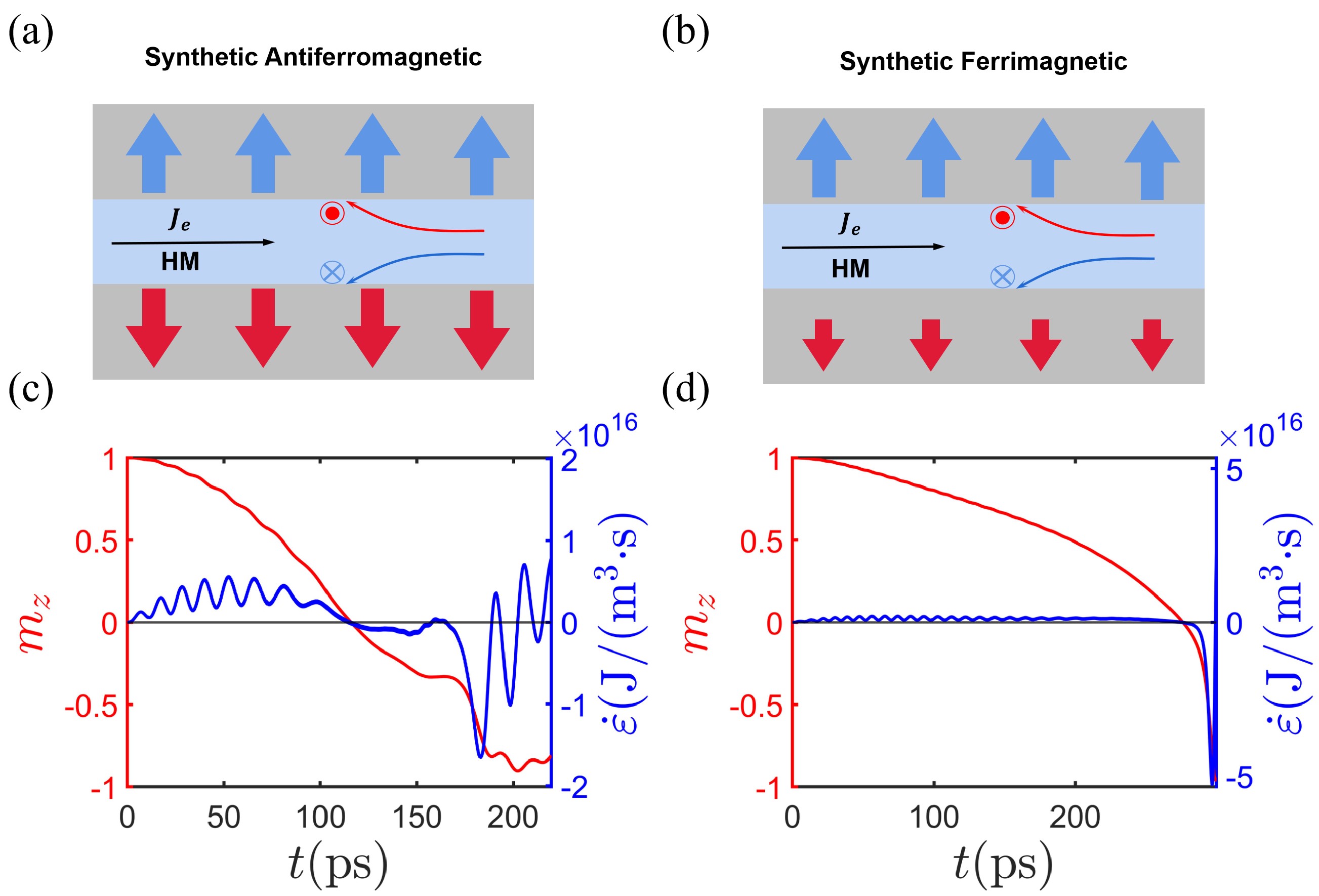
Later on, we examined the CCP driven switching of perpendicular SFi states with a small net magnetization as saturation magnetizations of upper and lower layers are set as A/m and A/m respectively. In addition, other material parameters as well as the dimensions are same as the previously studied FM system. Similar to SAF, we apply the rotating CCP in the sandwich layer and thus the transverse spin currents, which are generated by the spin-Hall effect can flow in the upper and lower FM layers which are align in opposite directions as shown in the Fig. 7(b). In this way, both the spin current components (upper and lower) from the CCP can be utilized efficiently to drive the reversal of magnetic state of both layers (from up-down to down-up). Thus we interestingly found that, with the minimal current density MA/cm2, = 44 GHz and optimal GHz, the ultrafast reversals of of the both layer are achieved. Red line in the Fig. 7(d) shows the switching of of a single cell from the upper layer while blue line represents the trend of the energy changing rate of the magnetization of a single cell, contributed by both DL- and FL-torque components. Note that, blue line in Fig. 7(d), the trend of the rate of change of energy absorption (emission) before (after) crossing the energy barrier is similar to the FM system (solid blue line in Fig. 5). Thus the physical mechanism and explanation of the ultrafast reversal of SFi under the CCP is analogous to the FM system. However, it is mentioned that, in compare to SAF switching, the minimal current needed for SFi switching is significantly lower.
IV Discussion and Conclusions
In this study, we investigated the parameters necessary for efficient and ultrafast switching in field-free spin-orbit torque (SOT) systems driven by a circularly polarized current pulse (CCP). We found that a wide range of initial frequencies around the ferromagnetic resonance frequency (FMR) allowed for ultrafast switching. By increasing the controlling parameter , we were able to achieve ultrafast switching, as the switching time is close to the pulse duration of the CCP. Additionally, we found that increasing the current density led to more efficient energy absorption and emission. However, generating the CCP in the laboratory remains a challenge, and recent studies may provide insight into how to generate such a pulse [67, 35, 32, 25, 68, 69].
Our study demonstrated that utilizing both FL- and DL-torques in the CCP of 0.92ns can drive an ultrafast and efficient magnetization reversal in 0.94ns without any additional means of symmetry breaking. We found that the critical current density is strongly reduced in comparison to conventional SOT-reversal for a certain range of CCP frequencies. This field-free ultrafast reversal is driven by the efficient energy absorption and emission of the magnetization from and to the fields of FL- and DL-torques before and after crossing over the energy barrier. The pulse duration of the CCP is close to the reversal time and does not require precise adjustment. This CCP-driven switching is robust at room temperature.
We also extended this strategy to reverse the magnetic states of perpendicular SAF and SFi systems by applying the CCP in the sandwiched layer, acting as a spin source for upper and lower layers. We found that the CCP, with significantly lower current density, can induce field-free ultrafast and efficient switching of magnetic states of SAF and SFi systems with a similar physical mechanism. These findings enhance the basic understanding of SOT-reversal and provide a way to realize novel SOT-MRAM devices with FM, SAF, or SFi free layers.
Acknowledgements.
M.T.I. acknowledges the support of National Natural Science Foundation of China (Grant No. 12350410352) and National Key R and D Program of China (Grant No. 2021YFA1202200). X.R.W. acknowledges the support of Hong Kong RGC Grants (No. 16300522, 16300523, and 16302321). X.S.W. acknowledges support from the Natural Science Foundation of China (NSFC) (Grants No. 11804045 and No. 12174093) and the Fundamental Research Funds for the Central Universities.Appendix A The calculation of the rate of energy change
In the appendix, we present a detailed derivation of the rate of change of energy of magnetization, , in equation (5).
In this context, we treat the spin-orbit torques (SOT) as an external torque, meaning that the energy associated with the effective field generated by SOT is not accounted for in the system’s energy. This enables us to concentrate solely on the inherent energy variations of the system. The effective field is defined as follows:
| (7) |
By making suitable adaptations, the energy density can be formulated in the following manner:
| (8) |
By substituting the explicit Landau-Lifshitz-Gilbert (LLG) equation into the above equation, we derive the following expression:
| (9) |
The first term, , on the right-hand side is always negative as it is proportional to , and is always smaller than . The second term, , represents the energy variation resulting from the influence of the SOT torque, and its sign can be positive or negative. Where is the magnetization direction and is the spin polarization direction which is related to the electric current direction as . and can be represented in spherical coordinates as:
| (10) |
| (11) |
Similarly, the effective field is also a function of :
| (12) |
where , , and are the demagnetization factors in the x, y, and z directions respectively, satisfying the condition . For our system, it is typically observed that and tend to approach zero. As a result, the effective field can be simplified as . Substituting this expression into the equation yields the following:
| (13) |
Let , then:
| (14) |
References
- Slonczewski [1996] J. Slonczewski, Current-driven excitation of magnetic multilayers, J. Magn. Magn. Mater. 159, L1 (1996).
- Tsoi et al. [1998] M. Tsoi, A. G. M. Jansen, J. Bass, W.-C. Chiang, M. Seck, V. Tsoi, and P. Wyder, Excitation of a magnetic multilayer by an electric current, Phys. Rev. Lett. 80, 4281 (1998).
- Katine et al. [2000] J. A. Katine, F. J. Albert, R. A. Buhrman, E. B. Myers, and D. C. Ralph, Current-driven magnetization reversal and spin-wave excitations in pillars, Phys. Rev. Lett. 84, 3149 (2000).
- Waintal et al. [2000] X. Waintal, E. B. Myers, P. W. Brouwer, and D. C. Ralph, Role of spin-dependent interface scattering in generating current-induced torques in magnetic multilayers, Phys. Rev. B 62, 12317 (2000).
- Sun [2000] J. Z. Sun, Spin-current interaction with a monodomain magnetic body: A model study, Phys. Rev. B 62, 570 (2000).
- Stiles and Zangwill [2002] M. D. Stiles and A. Zangwill, Anatomy of spin-transfer torque, Phys. Rev. B 66, 014407 (2002).
- Bazaliy et al. [2004] Y. B. Bazaliy, B. A. Jones, and S.-C. Zhang, Current-induced magnetization switching in small domains of different anisotropies, Phys. Rev. B 69, 094421 (2004).
- Koch et al. [2004] R. H. Koch, J. A. Katine, and J. Z. Sun, Time-resolved reversal of spin-transfer switching in a nanomagnet, Phys. Rev. Lett. 92, 088302 (2004).
- Wetzels et al. [2006] W. Wetzels, G. E. W. Bauer, and O. N. Jouravlev, Efficient magnetization reversal with noisy currents, Phys. Rev. Lett. 96, 127203 (2006).
- Ikeda et al. [2007] S. Ikeda, J. Hayakawa, Y. M. Lee, F. Matsukura, Y. Ohno, T. Hanyu, and H. Ohno, Magnetic tunnel junctions for spintronic memories and beyond, IEEE Trans. Electron Devices 54, 991 (2007).
- Manchon and Zhang [2008] A. Manchon and S. Zhang, Theory of nonequilibrium intrinsic spin torque in a single nanomagnet, Phys. Rev. B 78, 212405 (2008).
- Mihai Miron et al. [2010] I. Mihai Miron, G. Gaudin, S. Auffret, B. Rodmacq, A. Schuhl, S. Pizzini, J. Vogel, and P. Gambardella, Current-driven spin torque induced by the rashba effect in a ferromagnetic metal layer, Nat. Mater. 9, 230 (2010).
- Wadley et al. [2016] P. Wadley, B. Howells, J. Železný, C. Andrews, V. Hills, R. P. Campion, V. Novák, K. Olejník, F. Maccherozzi, S. S. Dhesi, S. Y. Martin, T. Wagner, J. Wunderlich, F. Freimuth, Y. Mokrousov, J. Kuneš, J. S. Chauhan, M. J. Grzybowski, A. W. Rushforth, K. W. Edmonds, B. L. Gallagher, and T. Jungwirth, Electrical switching of an antiferromagnet, Science 351, 587 (2016).
- Fukami et al. [2016a] S. Fukami, T. Anekawa, C. Zhang, and H. Ohno, A spin–orbit torque switching scheme with collinear magnetic easy axis and current configuration, Nat. Nanotechnol. 11, 621 (2016a).
- Wang and Chien [2013] W. G. Wang and C. L. Chien, Voltage-induced switching in magnetic tunnel junctions with perpendicular magnetic anisotropy, J. Phys. D: Appl. Phys. 46, 074004 (2013).
- Miron et al. [2011] I. M. Miron, K. Garello, G. Gaudin, P.-J. Zermatten, M. V. Costache, S. Auffret, S. Bandiera, B. Rodmacq, A. Schuhl, and P. Gambardella, Perpendicular switching of a single ferromagnetic layer induced by in-plane current injection, Nature 476, 189 (2011).
- Liu et al. [2012a] L. Liu, O. J. Lee, T. J. Gudmundsen, D. C. Ralph, and R. A. Buhrman, Current-induced switching of perpendicularly magnetized magnetic layers using spin torque from the spin hall effect, Phys. Rev. Lett. 109, 096602 (2012a).
- Endoh and Honjo [2018] T. Endoh and H. Honjo, A recent progress of spintronics devices for integrated circuit applications, J. Low Power Electron. Appl. 8, 44 (2018).
- Železný et al. [2014] J. Železný, H. Gao, K. Výborný, J. Zemen, J. Mašek, A. Manchon, J. Wunderlich, J. Sinova, and T. Jungwirth, Relativistic néel-order fields induced by electrical current in antiferromagnets, Phys. Rev. Lett. 113, 157201 (2014).
- Gambardella and Miron [2011] P. Gambardella and I. M. Miron, Current-induced spin–orbit torques, Philos. Trans. R. Soc. Math. Phys. Eng. Sci. 369, 3175 (2011).
- Liu et al. [2012b] L. Liu, C.-F. Pai, Y. Li, H. W. Tseng, D. C. Ralph, and R. A. Buhrman, Spin-torque switching with the giant spin hall effect of tantalum, Science 336, 555 (2012b).
- Parkin [1991] S. S. P. Parkin, Systematic variation of the strength and oscillation period of indirect magnetic exchange coupling through the 3d, 4d, and 5dtransition metals, Phys. Rev. Lett. 67, 3598 (1991).
- Yu et al. [2014a] G. Yu, P. Upadhyaya, Y. Fan, J. G. Alzate, W. Jiang, K. L. Wong, S. Takei, S. A. Bender, L.-T. Chang, Y. Jiang, M. Lang, J. Tang, Y. Wang, Y. Tserkovnyak, P. K. Amiri, and K. L. Wang, Switching of perpendicular magnetization by spin–orbit torques in the absence of external magnetic fields, Nat. Nanotechnol. 9, 548 (2014a).
- Fukami et al. [2016b] S. Fukami, C. Zhang, S. DuttaGupta, A. Kurenkov, and H. Ohno, Magnetization switching by spin–orbit torque in an antiferromagnet–ferromagnet bilayer system, Nat. Mater. 15, 535 (2016b).
- Manchon et al. [2019] A. Manchon, J. Železný, I. Miron, T. Jungwirth, J. Sinova, A. Thiaville, K. Garello, and P. Gambardella, Current-induced spin-orbit torques in ferromagnetic and antiferromagnetic systems, Rev. Mod. Phys. 91, 035004 (2019).
- Ryu et al. [2020] J. Ryu, S. Lee, K. Lee, and B. Park, Current-induced spin–orbit torques for spintronic applications, Adv. Mater. 32, 1907148 (2020).
- Sinova et al. [2015] J. Sinova, S. O. Valenzuela, J. Wunderlich, C. Back, and T. Jungwirth, Spin hall effects, Rev. Mod. Phys. 87, 1213 (2015).
- Kim et al. [2012a] K.-W. Kim, S.-M. Seo, J. Ryu, K.-J. Lee, and H.-W. Lee, Magnetization dynamics induced by in-plane currents in ultrathin magnetic nanostructures with rashba spin-orbit coupling, Phys. Rev. B 85, 180404 (2012a).
- Chen et al. [2017] J.-Y. Chen, M. DC, D. Zhang, Z. Zhao, M. Li, and J.-P. Wang, Field-free spin-orbit torque switching of composite perpendicular layers utilized for three-terminal magnetic tunnel junctions, Appl. Phys. Lett. 111, 012402 (2017).
- Yu et al. [2014b] G. Yu, L.-T. Chang, M. Akyol, P. Upadhyaya, C. He, X. Li, K. L. Wong, P. K. Amiri, and K. L. Wang, Current-driven perpendicular magnetization switching in films with lateral structural asymmetry, Appl. Phys. Lett. 105, 102411 (2014b).
- Chen et al. [2018] T.-Y. Chen, H.-I. Chan, W.-B. Liao, and C.-F. Pai, Current-induced spin-orbit torque and field-free switching in Mo-based magnetic heterostructures, Phys. Rev. Appl. 10, 044038 (2018).
- Kim et al. [2012b] J. Kim, J. Sinha, M. Hayashi, M. Yamanouchi, S. Fukami, T. Suzuki, S. Mitani, and H. Ohno, Layer thickness dependence of the current-induced effective field vector in TaCoFeBMgO, Nat. Mater. 12, 240 (2012b).
- Garello et al. [2013] K. Garello, I. M. Miron, C. O. Avci, F. Freimuth, Y. Mokrousov, S. Blügel, S. Auffret, O. Boulle, G. Gaudin, and P. Gambardella, Symmetry and magnitude of spin–orbit torques in ferromagnetic heterostructures, Nat. Nanotechnol. 8, 587 (2013).
- Avci et al. [2014] C. O. Avci, K. Garello, C. Nistor, S. Godey, B. Ballesteros, A. Mugarza, A. Barla, M. Valvidares, E. Pellegrin, A. Ghosh, I. M. Miron, O. Boulle, S. Auffret, G. Gaudin, and P. Gambardella, Fieldlike and antidamping spin-orbit torques in as-grown and annealed layers, Phys. Rev. B 89, 214419 (2014).
- Qiu et al. [2014] X. Qiu, P. Deorani, K. Narayanapillai, K.-S. Lee, K.-J. Lee, H.-W. Lee, and H. Yang, Angular and temperature dependence of current induced spin-orbit effective fields in nanowires, Sci. Rep. 4, 4491 (2014).
- Akyol et al. [2015] M. Akyol, J. G. Alzate, G. Yu, P. Upadhyaya, K. L. Wong, A. Ekicibil, P. Khalili Amiri, and K. L. Wang, Effect of the oxide layer on current-induced spin-orbit torques in and structures, Appl. Phys. Lett. 106, 032406 (2015).
- Yoon et al. [2017] J. Yoon, S.-W. Lee, J. H. Kwon, J. M. Lee, J. Son, X. Qiu, K.-J. Lee, and H. Yang, Anomalous spin-orbit torque switching due to field-like torque–assisted domain wall reflection, Sci. Adv. 3, e1603099 (2017).
- Wang [2012] D. Wang, Spin-orbit field switching of magnetization in ferromagnetic films with perpendicular anisotropy, Appl. Phys. Lett. 100, 212405 (2012).
- Thirion et al. [2003] C. Thirion, W. Wernsdorfer, and D. Mailly, Switching of magnetization by nonlinear resonance studied in single nanoparticles, Nat. Mater. 2, 524 (2003).
- Rivkin and Ketterson [2006] K. Rivkin and J. B. Ketterson, Magnetization reversal in the anisotropy-dominated regime using time-dependent magnetic fields, Appl. Phys. Lett. 89, 252507 (2006).
- Woltersdorf and Back [2007] G. Woltersdorf and C. H. Back, Microwave assisted switching of single domain elements, Phys. Rev. Lett. 99, 227207 (2007).
- Sun and Wang [2006a] Z. Z. Sun and X. R. Wang, Theoretical limit of the minimal magnetization switching field and the optimal field pulse for stoner particles, Phys. Rev. Lett. 97, 077205 (2006a).
- Sun and Wang [2006b] Z. Z. Sun and X. R. Wang, Strategy to reduce minimal magnetization switching field for stoner particles, Phys. Rev. B 73, 092416 (2006b).
- Sun and Wang [2006c] Z. Z. Sun and X. R. Wang, Magnetization reversal through synchronization with a microwave, Phys. Rev. B 74, 132401 (2006c).
- Barros et al. [2011] N. Barros, M. Rassam, H. Jirari, and H. Kachkachi, Optimal switching of a nanomagnet assisted by microwaves, Phys. Rev. B 83, 144418 (2011).
- Barros et al. [2013] N. Barros, H. Rassam, and H. Kachkachi, Microwave-assisted switching of a nanomagnet: Analytical determination of the optimal microwave field, Phys. Rev. B 88, 014421 (2013).
- Cai et al. [2013] L. Cai, D. A. Garanin, and E. M. Chudnovsky, Reversal of magnetization of a single-domain magnetic particle by the ac field of time-dependent frequency, Phys. Rev. B 87, 024418 (2013).
- Islam et al. [2018] M. T. Islam, X. S. Wang, Y. Zhang, and X. R. Wang, Subnanosecond magnetization reversal of a magnetic nanoparticle driven by a chirp microwave field pulse, Phys. Rev. B 97, 224412 (2018).
- Islam et al. [2021a] M. Islam, M. Pikul, and X. Wang, Thermally assisted magnetization reversal of a magnetic nanoparticle driven by a down-chirp microwave field pulse, J. Magn. Magn. Mater. 537, 168174 (2021a).
- Zhang et al. [2018] Y. Zhang, H. Y. Yuan, X. S. Wang, and X. R. Wang, Breaking the current density threshold in spin-orbit-torque magnetic random access memory, Phys. Rev. B 97, 144416 (2018).
- Vlasov et al. [2022] S. M. Vlasov, G. J. Kwiatkowski, I. S. Lobanov, V. M. Uzdin, and P. F. Bessarab, Optimal protocol for spin-orbit torque switching of a perpendicular nanomagnet, Phys. Rev. B 105, 134404 (2022).
- Hirsch [1999] J. E. Hirsch, Spin hall effect, Phys. Rev. Lett. 83, 1834 (1999).
- MacNeill et al. [2016] D. MacNeill, G. M. Stiehl, M. H. D. Guimaraes, R. A. Buhrman, J. Park, and D. C. Ralph, Control of spin–orbit torques through crystal symmetry in bilayers, Nat. Phys. 13, 300 (2016).
- Humphries et al. [2017] A. M. Humphries, T. Wang, E. R. J. Edwards, S. R. Allen, J. M. Shaw, H. T. Nembach, J. Q. Xiao, T. J. Silva, and X. Fan, Observation of spin-orbit effects with spin rotation symmetry, Nat. Commun. 8, 911 (2017).
- Gilbert [2004] T. Gilbert, A phenomenological theory of damping in ferromagnetic materials, IEEE Trans. Magn. 40, 3443 (2004).
- Legrand et al. [2015] W. Legrand, R. Ramaswamy, R. Mishra, and H. Yang, Coherent subnanosecond switching of perpendicular magnetization by the fieldlike spin-orbit torque without an external magnetic field, Phys. Rev. Appl. 3, 064012 (2015).
- Islam et al. [2021b] M. T. Islam, M. A. S. Akanda, M. A. J. Pikul, and X. Wang, Fast magnetization reversal of a magnetic nanoparticle induced by cosine chirp microwave field pulse, J. Phys.: Condens.Matter 34, 105802 (2021b).
- Vansteenkiste et al. [2014] A. Vansteenkiste, J. Leliaert, M. Dvornik, M. Helsen, F. Garcia-Sanchez, and B. Van Waeyenberge, The design and verification of mumax3, AIP Adv. 4, 107133 (2014).
- Islam et al. [2019] M. T. Islam, X. S. Wang, and X. R. Wang, Thermal gradient driven domain wall dynamics, J. Phys.: Condens.Matter 31, 455701 (2019).
- Jungwirth et al. [2016] T. Jungwirth, X. Marti, P. Wadley, and J. Wunderlich, Antiferromagnetic spintronics, Nat. Nanotechnol. 11, 231 (2016).
- MacDonald and Tsoi [2011] A. H. MacDonald and M. Tsoi, Antiferromagnetic metal spintronics, Philos. Trans. R. Soc. Math. Phys. Eng. Sci. 369, 3098 (2011).
- Bandiera et al. [2010] S. Bandiera, R. C. Sousa, Y. Dahmane, C. Ducruet, C. Portemont, V. Baltz, S. Auffret, I. L. Prejbeanu, and B. Dieny, Comparison of synthetic antiferromagnets and hard ferromagnets as reference layer in magnetic tunnel junctions with perpendicular magnetic anisotropy, IEEE Magn. Lett. 1, 3000204 (2010).
- Jenkins et al. [2019] S. Jenkins, A. Meo, L. E. Elliott, S. K. Piotrowski, M. Bapna, R. W. Chantrell, S. A. Majetich, and R. F. L. Evans, Magnetic stray fields in nanoscale magnetic tunnel junctions, J. Phys. D: Appl. Phys. 53, 044001 (2019).
- Yakata et al. [2009] S. Yakata, H. Kubota, T. Sugano, T. Seki, K. Yakushiji, A. Fukushima, S. Yuasa, and K. Ando, Thermal stability and spin-transfer switchings in mgo-based magnetic tunnel junctions with ferromagnetically and antiferromagnetically coupled synthetic free layers, Appl. Phys. Lett. 95, 242504 (2009).
- Yoshida et al. [2013] C. Yoshida, T. Takenaga, Y. Iba, Y. Yamazaki, H. Noshiro, K. Tsunoda, A. Hatada, M. Nakabayashi, A. Takahashi, M. Aoki, and T. Sugii, Enhanced thermal stability in perpendicular top-pinned magnetic tunnel junction with synthetic antiferromagnetic free layers, IEEE Trans. Magn. 49, 4363 (2013).
- Bran et al. [2009] C. Bran, A. B. Butenko, N. S. Kiselev, U. Wolff, L. Schultz, O. Hellwig, U. K. Rößler, A. N. Bogdanov, and V. Neu, Evolution of stripe and bubble domains in antiferromagnetically coupled multilayers, Phys. Rev. B 79, 024430 (2009).
- Polley et al. [2023] D. Polley, A. Pattabi, A. Rastogi, K. Jhuria, E. Diaz, H. Singh, A. Lemaitre, M. Hehn, J. Gorchon, and J. Bokor, Picosecond spin-orbit torque–induced coherent magnetization switching in a ferromagnet, Sci. Adv. 9, eadh5562 (2023).
- Filianina et al. [2020] M. Filianina, J.-P. Hanke, K. Lee, D.-S. Han, S. Jaiswal, A. Rajan, G. Jakob, Y. Mokrousov, and M. Kläui, Electric-field control of spin-orbit torques in perpendicularly magnetized films, Phys. Rev. Lett. 124, 217701 (2020).
- Ding et al. [2020] S. Ding, A. Ross, D. Go, L. Baldrati, Z. Ren, F. Freimuth, S. Becker, F. Kammerbauer, J. Yang, G. Jakob, Y. Mokrousov, and M. Kläui, Harnessing orbital-to-spin conversion of interfacial orbital currents for efficient spin-orbit torques, Phys. Rev. Lett. 125, 177201 (2020).