Surface recoil force on dielectric nano–particles enhancement via graphene acoustic surface plasmons excitation: non–local effects consideration
Abstract
Controlling opto–mechanical interactions at sub–wavelength levels is of great importance in academic science and nano–particle manipulation technologies. This letter focuses on the improvement of the recoil force on nano–particles placed close to a graphene–dielectric–metal structure. The momentum conservation involving the non–symmetric excitation of acoustic surface plasmons (ASPs), via near field circularly polarized dipolar scattering, implies the occurrence of a huge momentum kick on the nano–particle. Owing to the high wave–vector values entailed in the near field scattering process, it has been necessary to consider the non–locality of the graphene electrical conductivity to explore the influence of the scattering loss on this large–wave–vector region, which is neglected by the semi–classical model. Surprisingly, the contribution of ASPs to the recoil force is negligibly modified when the non–local effects are incorporated through the graphene conductivity. On the contrary, our results show that the contribution of the non–local scattering loss to this force becomes dominant when the particle is placed very close to the graphene sheet and that it is mostly independent of the dielectric thickness layer. Our work can be helpful for designing new and better performing large–plasmon momentum opto–mechanical structures using scattering highly dependent of the polarization for moving dielectric nano–particles.
pacs:
81.05.ue,73.20.Mf,78.68.+m,42.50.PqKeywords:graphene, surface plasmons, non–local effects, plasmonics
The ability to control the state of movement of nano–particles by exchanging momentum with light is of great interest in chemical and biological applications. Besides manipulation using structured beams, which has allowed the development of modern approaches for trapping into small regions, pushing or pulling forces or rotating nano–particles [Chen-bessel, 2, 3], the use of optical cavities enabling highly confined optical modes has emerged as a new degree of freedom in the last ten years. These configurations, based on plane wave excitation of the eigenmodes of the optical structure, have aroused an increasing interest due to their capability for providing optical trapping beyond the diffraction limit, because they are less sensitive to accurate positioning and alignment of laser beams and for not requiring translating any focused beam to move particles [4, 5]. An outstanding kind of such forces are the recoil force acting on dielectric nano–particles coming from the metallic surface plasmons (SPs) non-symmetric excitation by plane wave incidence [6, 7, 2019].
The advent of plasmonic materials at terahertz (THz) and infrared (IR) region, such as graphene, has aroused an interest on moving some plasmonic force generation techniques, currently working in the visible region, to those frequency ranges [9, 10, 11, 12, 13, 14]. The main idea behind it is to avoid the highly power losses, resulting in heat dissipation by Joule effect limiting the performance for manipulating living biospecimens, commonly appearing on metallic plasmons excitation [15, 16, 17]. Since the recoil force on dipolar particles largely depend on momentum exchanging via surface plasmon asymmetric excitation, the improvement of these force intensities can be reached provided that the particle be placed near a structure supporting SPs with large wave–vector. In this way, the particle will be able to receive a huge kick, when it is compared with that provided by the photon, as consequence of momentum exchanging with SPs.
Furthermore, it is known that graphene–dielectric–metal structures support SPs with huge wave–vectors [18, 19, 20], named acoustic surface plasmons (ASPs) due to a linear dependence between frequency and wave–vector, a property that makes them ideal candidates for THz recoil force enhancement.
The aim of this work goes in that direction. In virtue of the large wave–vector values attained in the scattering process, a phenomenon that is more pronounced as the nano–particle is closed to the graphene sheet, the spacial variations of the electric field can exceed the classical limit and, consequently, the non–locality or spatial dispersion in electric conductivity arises [22]. In consequence, we have considered the graphene as an infinitesimally thin layer characterized by the non–local conductivity following the Lindhard–Mermin model [23] and we compared the results with those obtained by applying the local theory. Note that, unlike in the modern theory of optical forces, where non–local effects refer to the optomechanical manifestation of illumination in the vicinity of the particle [24], in this work we use this term to represent the dispersion in the graphene conductivity.
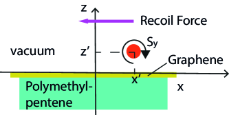
The proposed structure here studied composes of a dielectric layer with relative permittivity (corresponding to Polymethylpentene) of thickness coated with graphene (electrical conductivity , and are the angular frequency and the wave–vector, respectively) and placed on top of a metallic medium (Figure 1). A dielectric nano–particle is placed above the structure, in vacuum medium (), at position .
It is known that, under certain illumination conditions, a particle can acquire an induced rotating dipole moment giving rise to a spin induced on it. When such a particle is placed close to the surface, near zero in our system of reference, the near scattered field excites only ASPs with similar spin leading to ASPs traveling towards a determined direction along the graphene sheet. Therefore, a net force, which is opposed to the ASPs propagation direction, appears as a consequence of the momentum conservation. This recoil force is the source for the pulling force (a force pulling the particle towards the source light) [6] or lateral force (a force whose direction is perpendicular to the incident wave) generation [8]. In both cases, the magnitude of the force can be calculated in terms of the spin , which depends on induced dopole moment on the nano–particle , and the geometrical and constitutive parameters of the structure. Without loss of generality, we suppose that the induced dipole moment is along the direction, with and, consequently, the optical force results in the direction, where the sign or depends on the phase of the nominator, that is, on the phase difference between the induced dipole moments along the and directions. This situation could correspond to the case for which the particle is illuminated by circularly polarized plane wave at grazing incidence, i.e., with an incident wave vector almost parallel to the axis [8], or by linearly polarized plane wave with the electric field contained in the incidence plane ( polarization) [6, 17]. In such cases, the recoil force is written as [8],
| (1) |
where is the normalized component of the propagation constant along the surface, is the photon wave–vector in vacuum, is the vacuum speed of light, and is the power emitted by the same dipole in an unbounded medium 1 (vacuum in our case), this is, far from any structure, and is the vacuum permittivity. For a clear discussion, we have introduced the quantity as the force spectrum function,
| (2) |
where is the reflection coefficient for polarization with
| (3) |
| (4) |
and is the impedance vacuum.
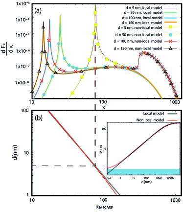
In our calculations, we have chosen m-1 corresponding to frequency THz. Without loss of generality, we consider the case , corresponding to a circular polarized induced dipole moment . To analyze the main contributions to the force, in Figure 2 we have plotted the force spectrum function as a function of the normalized wave–vector for nm and for different values of the dielectric thickness . As we can expect, for low values of both the local and non–local calculations give similar results. In this spectral region, we observe a pronounced peak corresponding to ASPs excitation. The spectral position of these peaks, which are the main contributions to the force (1) in the low wave–vector region (low– region), is largely depending on the thickness , as can be seen in Figure 2a. To clarify, in Figure 1b we have calculated the real part of the ASP propagation constant, , as a function of the thickness in the same wave–vector scale as in Figure 2a. To do this, we have solved the modes dispersion equation, i.e., the zeroes of the denominator of the reflection coefficient , by using a Newton–Raphson method adapted to the complex variable [21]. We see that the curves calculated using the local and non–local conductivity are almost indistinguishable, having a little difference for values of small enough. For example, the calculated real parts of the ASP propagation constant for nm are and for the local and non–local calculation, respectively. The difference between these two values, also noted by the different spectral positions of the plasmon peaks in Figure 2a, agree with the fact that the spatial dispersion effects begin to manifest themselves for normalized wave–vector values of the order of 300 [22, 25]. This behaviour can be visualized in the inset in Figure 2b where we have plotted the plasmon velocity as a function of the thickness . We observe that the velocity calculated with the local approximation begins to reduce appreciably with respect to the non–local approximation for values of lower than nm.
On the other hand, on the high– region, a great difference between local and non–local calculations appears, as can be seen in Figure 2a for . This condition coincides with that as the wave–vector enters on the intraband Landau damping domain, where , and are the Fermi wave–vector and energy, respectively. On this spectral region, the values of the force spectral function calculated by using the non–local conductivity exceed those corresponding to the local conductivity by more than one order of magnitude. Similar results about non–local effects affecting the spectrum function on the large in–plane–wave–vectors region, but in the framework of the spontaneous emission of an atom in front of a metallic slab, have been previously reported in [26]. In addition, from Figure 2a we note that, in this spectral region, there is no noticeable difference between the non–local curves for different values of , which means that the spatial dispersion on the graphene conductivity is mostly independent of the thickness of the dielectric layer.
Next, we have calculated the lateral force normalized with respect to the power , i.e., in units of . To avoid numerical inaccuracies coming from singularities falling near the real axis (plasmon propagation constant ), by using the Cauchy theorem we have deformed the original integration path, which is along the real and positive semi–axis, to one elliptical path passing on the negative imaginary semi–plane [17].
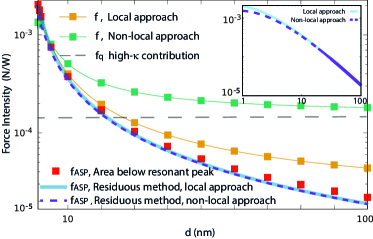
In Figure 3 we have plotted the normalized force together with the ASP and the high– contributions, and , as a function of the thickness . As in Figure 2, the position of the particle is maintained at nm. The ASP contribution can be achieved in two ways: the first by calculating the area below the ASP peak in the force spectrum curves plotted in Figure 2a into a spatial bandwidth that embraces the whole resonant peak, and the other, by using the residues theorem to obtain an analytical expression for the ASP contribution to the normalized force (see Supporting Information, Section S1),
| (5) |
where, in virtue of the fact that , we used the quasistatic approximation . We observe that both calculations agree reasonably well. Note that the ASP contribution shows small differences between local and non–local calculation for values of smaller that nm (see inset in Figure 3). This is true because the propagation constant values calculated within these approaches begin to differentiate below nm (see Figure 2b). Regarding to the total force, from Figure 3 we can see that the values calculated by using the non–local conductivity are noticeably more larger than those obtained by using the local conductivity. For instance, the non–local force exceeds the local by about one order of magnitude for thickness nm. This behaviour arises from the fact that the local calculation does not takes into account the intraband Landau damping (electron–hole excitation) which dominates the scattering loss in the high– region.
On the other hand, in the large region of Figure 2a the quasistatic approximation is valid. In this limit, , the higher– contribution to the recoil force can be approximated by
| (6) |
Even though the value of depends on , for we can consider that as a constant value, independent of , and equal to that corresponding for . The calculated value of (see Supporting Information, Section S2). With this value, the non–local contribution to the normalized recoil force (see Figure 3).
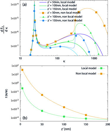
To investigate the dependence with the distance between the particle and graphene, in Figure 4a we have calculated the spectral function for various values of the distance, nm. The dielectric thickness is fixed at nm. We see that both the plasmon and the high– contributions increase as the distance decreases, i.e., as the particle approaches the graphene sheet. These increments can be understood by the dependence of this force contributions on distance, and for the SP and high– contributions, respectively. In addition, the difference between local and non–local effects is noticeably increased beyond . In this large– region, the contribution of the intraband Landau damping dominates over the plasmonic contribution and the resultant recoil force is largely enhanced due to this effect, as can be seen in Figure 4b, where we plotted the normalized force using the local and non–local formulations as functions of the distance maintaining nm fixed. The force values calculated with the non–local theory becomes two orders of magnitude, it is depending of , larger than those calculated by using the local theory. We have validated the results obtained by calculating the recoil force on dielectric cubes using full–wave simulations (see Supporting Information, Section S3).
In conclusion, we have compared the results referred to the optical recoil force on a dielectric nano–particle placed near a graphene–dielectric–metal planar structure using local and non–local electric conductivity approaches. We quantified the two main contributions to this force: the excitation of ASPs and intraband electron–hole pairs, this last appearing for higher values of the in–plane wave–vector. For values of the dielectric thickness layer grater than nm, the SP contribution almost does not depend on whether the used approach is local or non–local. On the contrary, the contribution of the high wave–vector region, given rise to electron–hole pairs in the conduction band of graphene and which is taking into account in the non local approach, dominates the momentum exchange process between the nanoparticle and the electromagnetic field.
We believe that our results can be valuable for the design of polarized–dependent opto–mechanical devices using near field scattering between nano–particles and plasmonic interfaces, in particular, when the particle is placed very close to the plasmonic surface where the non–local effects dominate the scattering process.
Acknowledgment
The authors acknowledge the financial supports of Universidad Austral O04-INV00020, Agencia Nacional de Promoción de la Investigacón, el desarrollo Tecnológico y la Innovación PICT-2020-SERIEA-02978 and Consejo Nacional de Investigaciones CientÃficas y Técnicas (CONICET).
References
- [1] J. Chen and J. Ng and Z. Lin and C. T. Chan, Optical pulling force, NATURE PHOTONICS 5, 531–534 (2011).
- [2] X. Li and J. Chen and Z. Lin and J. Ng, Optical pulling at macroscopic distances.Sci. Adv. 5, eaau7814 (2019).
- [3] L-M Zhou and X. Zhu and Y. Zheng and L. Wang and C. Huang and X Jiang and Y. Shiand F-W Sun and J. Hu, Superfast and sub-wavelength orbital rotation of plasmonic particles in focused Gaussian beams, Appl. Phys. Lett. 123, (2023).
- [4] R. Jin and Y. Xu and Z-G Dong and Y. Liu, “Optical Pulling Forces Enabled by Hyperbolic Metamaterials,” Nano Lett. 21, 10431–10437 (2021).
- [5] J. J. Kingsley–Smith and M. F. Picardi and L. Wei and A. V. Zayats and Francisco J. Rodríguez–FortunoOptical forces from near-field directionalities in planar structures, Phys. Rev. B 99, 235410 (2019)
- [6] Petrov, Mihail I and Sukhov, Sergey V and Bogdanov, Andrey A and Shalin, Alexander S and Dogariu, Aristide, Surface plasmon polariton assisted optical pulling force, Laser and Photonics Reviews 10, (2016)
- [7] H. Ferrari and V. Herrero and M. Cuevas,Optical pulling force on dielectric particles via metallic slab surface plasmon excitation: a comparison between transmission and reflection scheme, Optics Letters 48, (2023)
- [8] F. Rodríguez-Fortuno and N. Engheta and A. Martínez and A. V. Zayats, Lateral forces on circularly polarizable particles near a surface, Nat. Commun 6, 8799 (2015)
- [9] A. V. Maslov, Optical equilibrium for resonant particles induced by surface plasmons of two-dimensional materials, Phys. Rev. B 98, 235414 (2018).
- [10] P. Q. Liu and P. Paul, “Graphene Nanoribbon Plasmonic Conveyor Belt Network for Optical Trapping and Transportation of Nanoparticles,” ACS Photonics 7, (2020) 3456–3466
- [11] Z.i Shen, M. Becton, D. Han, X. Fang, X.Wang, L. Zhang, and X. Chen, “Terahertz plasmonic nanotrapping with graphene coaxial apertures,” Phys. Rev. A 102, 053507 (2020).
- [12] M. Samadi, S. Darbari and M. K. Moravvej–Farshi, “Numerical Investigation of Tunable Plasmonic Tweezers based on Graphene Stripes,” Sci. Rep. 7 14533 (2017)
- [13] A. F. da Mota, A. Martins, J. Weiner, P. Courteille, E. R. Martins, and B. V. Borges, “Design and analysis of nanopatterned graphene-based structures for trapping applications,” Phys. Rev. B 102, 085415 (2020)
- [14] H. Ferrari, C. J. Zapata-Rodríguez and M. Cuevas, “Terahertz binding of nanoparticles based on graphene surface plasmon excitations,” Journal of Quantitative Spectroscopy and Radiative Transfer 278, 108009 (2022).
- [15] K. Wang and E. Schonbrun and P. Steinvurzel and K. B. Crozier,“ Trapping and rotating nanoparticles using a plasmonic nano–tweezer with an integrated heat sink,” Nat. Commun. 2, (2011).
- [16] B. J. Roxworthy and K. D. Ko and A. Kumar and K. H. Fung and E. K. C. Chow and G. L. Liu and N. X. Fang and K. C. Toussaint Jr, “Application of plasmonic bowtie nanoantenna arrays for optical trapping, stacking, and sorting,” Nano Lett. 12, 796-801, (2012).
- [17] H. Ferrari, C. J. Zapata-Rodríguez and M. Cuevas, “Giant terahertz pulling force within an evanescent field induced by asymmetric wave coupling into radiative and bound modes,” Optics Letters 47, 4500-4503, (2022).
- [18] X. Gu and I-T Lin and J-M Liu, “ Extremely confined terahertz surface plasmon–polaritons in graphene–metal structures,” Applied Physics Letters 103, 071103, (2013).
- [19] P. A. D. Goncalves and T. Christensen and N. M. R. Peres and A. P. Jauho and I. Epstein and F. H. L. Koppens and M. Soljacic and N. A. Mortensen, “Quantum surface-response of metals revealed by acoustic graphene plasmons,” Nat. Commun. 12, 3271, (2021).
- [20] S. Chen and M. Autore and J. Li and P. Li, P. Alonso–Gonzalez and Z. Yang and L. Martin–Moreno, R. Hillenbrand and A. Y. Nikitin , Acoustic Graphene Plasmon Nanoresonators for Field-Enhanced Infrared Molecular Spectroscopy, ACS Photonics 4, 3089–3097 (2017).
- [21] M Zeller and M Cuevas and RA Depine, Surface plasmon polaritons in attenuated total reflection systems with metamaterials: homogeneous problem, Journal of Optical Society of America B 28, 2042–2047, (2011).
- [22] M. B. Lundeberg and Y. GAO and R. Asgari and C. Tan, B. Van Duppen and M. Autore and P. Alonso–Gonzalez and A. Woessner and K. Watanabe and T. Taniguchi and R. Hillenbrand and J. Hone and M. Polini and F. H. L. Koppens, Tuning quantum nonlocal effects in graphene plasmonics, SCIENCE 357, 187-191, (2017).
- [23] An Introduction to Graphene Plasmonics, P.A.D Goncalves and N.M.R Peres, (2016), World Scientific
- [24] Y. Zhou and X. Xu and Y. Zhang and M. Li and S.i Yan and M. Nieto–Vesperinas and B. Li and C–W Qiu and B.i Yao, Observation of high-order imaginary Poynting momentum optomechanics in structured light, PNAS 119, e2209721119, (2022)
- [25] S. Zare and B. Z. Tajani and S. Edalatpour, Effect of nonlocal electrical conductivity on near-field radiative heat transfer between graphene sheets, Physical Review B 105, 125416, (2022).
- [26] G. Ford and W. H. Weber, Electromagnetic interactions of molecules with metal surfaces, PHYSICS REPORTS Review Section of Physics Letters 113, 195-287, (1884).