Non-orthogonal cavity modes near exceptional points in the far field
Abstract
Non-orthogonal eigenstates are a fundamental feature of non-Hermitian systems and are accompanied by the emergence of nontrivial features. However, the platforms to explore non-Hermitian mode couplings mainly measure near-field effects, and the far-field behaviour remain mostly unexplored. Here, we study how a microcavity with non-Hermitian mode coupling exhibits eigenstate non-orthogonality by investigating the spatial field and the far-field polarization of cavity modes. The non-Hermiticity arises from asymmetric backscattering, which is controlled by integrating two scatterers of different size and location into a microdisk. We observe that the spatial field overlaps of two modes increases abruptly to its maximum value, whilst different far-field elliptical polarizations of two modes coalesce when approaching an exceptional point. We demonstrate such features experimentally by measuring the far-field polarization from the fabricated microdisks. Our work reveals the non-orthogonality in the far-field degree of freedom, and the integrability of the microdisks paves a way to integrate more non-Hermitian optical properties into nanophotonic systems.
I Introduction
Hermiticity in quantum mechanics guarantees orthogonality and completeness of eigenstates in a Hermitian system. In contrast, eigenstates of a non-Hermitian system are usually non-orthogonal. The eigenstate non-orthogonality is the fundamental and distinct feature to reveal the non-Hermiticity [1, 2], and provides the basis for key non-Hermitian phenomena such as the exceptional point (EP). In other words, the eigenstates and eigenvalues simultaneously coalesce at peculiar spectral singularities [3, 4, 5, 6]. EP enables many counter-intuitive phenomena including the chiral absorption [7, 8] and the strong modified spontaneous emission [9, 10]. Therefore, degrees of freedom that exhibit the eigenstate non-orthogonality are highly desired for functions of non-Hermitian quantum devices [11], such as discriminating non-Hermitian quantum states [12] and exploring non-Hermitian topological physics [13, 14].
Recently, optical systems have been attracting increasing interests in studying non-Hermitian physics [15, 16, 17, 18, 19], such as the whispering gallery mode (WGM) microcavities with asymmetric backscattering [20, 11], parity-time () or anti- symmetry [16, 21]. Such microcavities provide a platform to investigate the non-orthogonal modes in different degrees of freedom, such as propagation direction [11, 22], resonance frequency [23], intensity and beam dynamics [24, 25]. Another degree of freedom, far-field polarization, is correlated to the symmetry and the orthogonality of near field [26, 27, 28] and plays key roles in nanophotonics, such as single-photon sources [29], lasers [30], nonlinear frequency conversion [31] and topological optics [32] and structured light [33]. However, the measurement of WGM microcavities with non-Hermitian mode coupling or symmetry mainly relies on the near-field fiber coupling [11, 23]. As such, far-field polarization features of such WGM microcavities remain unexplored.
We use an ensemble of quantum dots as internal broad-band light sources to enable the far-field excitation [34], and use integrated internal scatterers to reduce the effects of disturbances from using external scatterers in the far-field collection. By integrating internal scatterers such as air cuts, bulges or holes, non-Hermitian mode coupling can be obtained in the WGM microcavities [35, 36, 37, 38]. Furthermore, compared to traditional cavities with non-Hermitian mode coupling realized by external scatterers or gain/loss, the integrated internal scatterers enable small-size designs with small mode volumes and large-scale on-chip integration. These two features provide the basis for studying non-Hermitian cavity quantum electrodynamics (QED) and quantum optical devices [39, 9, 40, 41, 42].
Here we study the polarization of far-field photoluminescence (PL) spectra from cavity modes in microcavities with non-Hermitian mode coupling around an EP. The non-Hermiticity in mode coupling is realized by the asymmetric backscattering from two internal weak scatterers of different size and location, and the mode non-orthogonality is further controlled by the relative angle between the two scatterers. We reveal the angle dependence of the spatial field distribution and the far field polarization as non-Hermitian features of the system. Approaching an EP, we observe that the spatial field overlap of two modes increases abruptly, and the far-field polarizations of two modes are nearly identical, corresponding to coalescent eigenstates at an EP. These polarization features are further demonstrated by experimental measurements of fabricated microdisks. Since our microdisks with internal weak scatterers can be integrated on-chip, the non-orthogonality based near- and far-field features enable further applications to integrate the non-Hermitian optical properties into nanophotonic systems.
II Results
II.1 Theoretical analysis
Left and right eigenstates, and , correspond to Hamiltonians and , respectively [43]. In contrast to a Hermitian system, in a non-Hermitian system we have . Therefore, the non-Hermitian system follows the bi-orthogonality , which is very challenging to be directly experimentally obtained. However, the self-orthogonality and , which follows for a Hermitian system, do not vanish for for a non-Hermitian system. This is the intrinsic difference between Hermitian and non-Hermitian systems. The non-orthogonality supports non-trivial phenomena such as chirality [11] and topology [44], therefore, it is one focus of theoretical and experimental investigations on non-Hermitian systems.
Non-Hermitian optical systems with non-Hermitian mode coupling have been achieved by the asymmetric backscattering between clockwise (CW) and counter-clockwise (CCW) traveling-wave modes in a WGM microcavity. These modes are quasinormal modes since the optical microcavity is non-conservative with energy loss [45, 46, 47]. We only focus on well confined transverse electric (TE) modes in the first radial order with a high quality (Q) factors [48] and dominating , and components, which can be easily experimentally observed in far-field photoluminescence (PL) spectra from microcavities with embedded self-assembled quantum dots as excitation sources[37, 49, 50, 51, 52]. Here the TE modes are labeled by with the azimuthal mode number . The cavity mode function follows and thus has antinodes along the cavity perimeter. is the azimuthal angle in the polar coordinate.
WGMs are very sensitive to nano-scale perturbations [53, 54, 55, 56]. These perturbations act as Rayleigh scatterers that introduce the backscattering coupling between CW and CCW modes, which are degenerate without scatterers. The non-Hermiticity in WGM mode coupling can be realized and modulated by the asymmetric backscattering from weak scatterers [20] or strong scatterers [38]. Here we consider a WGM cavity with two weak scatterers and use a two-mode approximation based Hamiltonian picture to analyze how the non-Hermiticity is controlled by the scatterers. The corresponding Hamiltonian using the traveling-wave basis and is written as
| (1) |
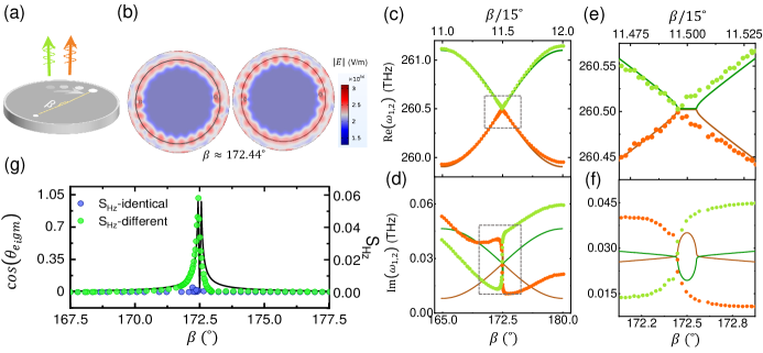
The terms and are complex because the scatterers induce a frequency shift and extra loss to the cavity modes, and they describe the backscattering effect from the two different weak scatterers, respectively. For more details about the backscattering, see Supplementary note 3 in supplementary materials (SMs). is the complex eigenvalues for the unperturbed microcavity, represents the complex frequency shift resulting from the two scatterers, and is the relative angle between the two scatterers, as illustrated in Fig. 1(a). Eigenvalues and eigenstates can be obtained respectively as
| (2) |
| (3) |
and . The eigenfrequencies are periodically modulated by with period for . To quantify the eigenstate non-orthogonality, we introduce , where we call and orthogonal (coalescent) if ().
When the two weak scatterers differ (), eigenstates exhibit non-orthogonality. In particular, EPs can be realized when one of the non-diagonal terms of in Eq. (1) vanishes near ( is an integer) and becomes defective [20, 57]. To further explore the non-Hermiticity, we calculate the dependence of and on for , and present the results in Fig. 1(c)-(g). The values for , and are deduced from complex eigenfrequencies in simulation results, for details see Theoretical calculations of eigenvalues in Methods. From eigenvalues in Eq. (2), it can be inferred that non-Hermitian degeneracy happens when , which is possible when , and . For every , there are two different that can satisfy this requirement, but correspond to different eigenmodes. As shown in Fig. 1(c)-(d), resonance frequencies (c) and decay rates (d) of two modes become degenerate symmetrically around with two EPs.
II.2 Simulation results
We implement numerical simulations using the finite element method. To control the non-Hermiticity, cylinder air holes are set in the microdisks with a thickness of 250 nm and a radius of 1 m as shown in Fig. 1(a). The two scatterers are defined by the radius , the distance from the microdisk center and the relative angle . We use nm and nm, which follows and to achieve for an EP [20]. Details about the designs and the simulation methods are presented in Methods and supplementary note 1 in SMs.
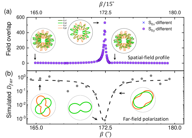
We focus on the spatial field distribution and far-field polarization of the two modes. At an EP, two modes propagate as traveling waves and coalesce into one mode with the same complex eigenfrequencies. As shown in Fig. 1(b), the contrast between near-field antinodes and nodes for becomes vague, exhibiting features similar to traveling wave. More obvious features like traveling wave rather than standing wave can be seen in Fig. S1(j) in SMs. Meanwhile, two modes have almost the same complex eigenvalues as shown in Fig. 1(e)-(f). and components of two modes distributed along a black circle on the microdisk surface as shown in Fig. 1(b) highly coincide at as shown in Fig. 2(a). In contrast, when away from the EP (e.g., ), an obvious spatial phase difference exists between and components of the two modes, as shown in Fig. 2(a). To describe the spatial field overlap of two modes, we define ( or to quantify the non-orthogonality. Take for example, we have
| (4) |
where is the normalized field extracted from the simulations. The normalization considers the field in the perfectly matched layer due to the non-Hermiticity of the quasinormal modes [45]. For details of the normalization, see Normalization of simulated spatial field in Methods. Figure 1(g) shows from the two-mode picture Eq. 1 and for two different holes (labeled by green circles) from the simulation with varying . Both two parameters, which quantify the non-orthogonality, increase abruptly when approaching the EP and reach their the maximum values at the EP. Similar changes also apply to (blue crosses) and (purple dots) as shown in Fig. 2(a), which exhibit the same trend but in a larger ratio versus compared to . By comparison, such high non-orthogonality is not observed for two identical holes as shown by the results in Fig. 1(g) (labeled by blue circles) and Fig. S2 (c) and (d) in Supplementary note 2 in SMs. The near-field distributions are strongly molded by the holes because of their direct effects on the eigenstate non-orthogonality. By comparison, the extra energy loss of the cavity caused by the scatterers is relatively weakly molded because it is affected by the spatial overlap between scatterers and mode field.
Note that in Fig. 1(g) indicates two EPs while only responds to one EP at . Another EP is expected to appear at based on the two-mode picture (Eq. 1). The deviation lies in the imperfection of the two-mode approximation model we use instead of the imperfection of the simulation mesh size, for example, only considering TE modes with a fixed is not a good assumption for internal scatterers [36] and and in the Hamiltonian are not always constant for different . Indeed, the two EPs correspond to two slightly different sets of scatter designs as predicted by the local basis theory [58], rather than the same design predicted by global basis in the two-mode picture. Further development is still needed to improve for theoretically describing such WGM cavities with non-Hermitian scattering physical process with multiple weak scatterers, especially near EPs. Nevertheless, our conclusions are further verified with the numerical simulations by solving Maxwell’s equations considering the propagation laws in different media and materials and subsequent experimental demonstrations.
The far-field polarization is correlated to the symmetry of the near-field distribution inside a cavity. For the cavity mode with highly symmetric near-field distribution, such as the L3 photonic crystal cavity, the linear far-field polarization can be predicted according to the parities of their in-plane electric field components [27, 26]. However, asymmetric backscattering redistributes the near field and disturbs the symmetry of mode field distribution, which makes the polarization very complex. In contrast to the linear polarization in L3 cavity, elliptical polarizations with different polarization angle and polarization degree are obtained for the two modes in the WGM cavities with non-Hermitian mode coupling. The numerical simulation results of typical cases are presented in the insets in Fig. 2(b). To describe the difference between two polarization ellipses, we consider both polarization angle and polarization degree and define
| (5) |
and are the polarization degree of two modes, defined as the ratio of the major axis to the minor axis in the polarization ellipse, while is the polarization angle difference (0∘ to 90∘) between two modes, which are illustrated in Fig. S4(a) in supplementary materials. The first term of describes the difference originating from the polarization degree difference between two modes, while the second term describes the difference originating from the polarization angle difference between two modes. For the second term, we multiply the polarization angle difference by the averaged polarization degree . This is because when approaching the circular polarization (), the difference in the polarization angle has less physical meaning. As shown in Fig. 2(b), decreases when approaching an EP and reaches the minimum value at an EP. The polar maps of two polarization ellipses can vary from relatively large with to relatively small also with , and coalesce as and at the EP.
II.3 Experimental results
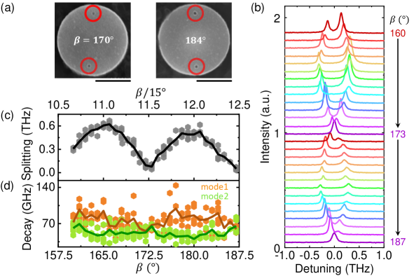
To experimentally demonstrate the far-field features, we fabricated microcavities with two holes according to the simulation results. We span from 160∘ to 200∘ with 1∘ increment, and fabricate five identical microdisks for each parameter. Figure 3(a) shows the typical SEM images, recorded for two microdisks with different . We use InAs quantum dots embedded inside the microdisks as the broad-band light sources for the far-field excitation of the cavity modes. In principle, all the cavity modes in the spectral range of PL emission from ensemble of quantum dots (QDs) can be observed and be tuned for achieving EPs if with proper scatterer design. However, we only focus on mode in this work. Specific details on the fabrication method and experimental setup can be found in Methods.
Figure 3(b) shows the PL spectra recorded from the microdisks with different . As shown, we observe that a pair of split peaks gradually emerge into one peak at and , in agreement with the and for realizing EPs predicted in theory discussed above. Figure 3(c)-(d) shows the statistics of the fitting results of the frequency splitting (c) and the decay rates (d) of the two modes. Here in Fig. 3(c) we use the difference between two mode frequencies, because the absolute cavity resonance wavelengths contains fluctuations arising from random fabrication errors and intrinsic backscattering [54].
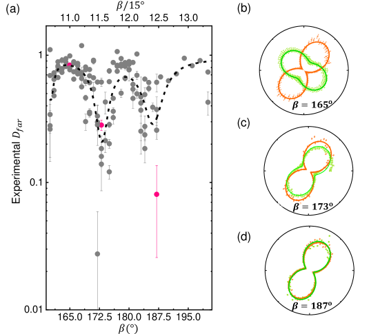
In Fig. 4(a) we present the experimental results of far-field polarization extracted from the PL spectra. As shown, varies quasi-periodically with with two clear dips in Fig. 4(a), corresponding to the coalescent polar maps of polarization ellipses predicted approaching EPs (Fig. 2(b)). The polarizations in three typical cases are presented in Fig. 4(b)-(d), corresponding to the three pink dots in Fig. 4(a). The case of in Fig. 4(b) corresponds to a small spatial overlap (165∘ in Fig. 2(a)) with the maximum frequency splitting and decay rate difference. As expected, the experimental polarization of spectra (Fig. 4(b)) shows that the polarization angle difference can reach up to , in good agreement with the prediction in Fig. 2(b). In contrast, for in Fig. 4(c), polar maps of two polarization ellipses have almost the same polarization angle but different polarization degree. For in Fig. 4(d), polar maps of two polarization ellipses are almost identical. These cases are consistent to the corresponding cases approaching EP as predicted in Fig. 2(b). The good agreement between the theory and the experiment further strengthens our conclusion that the far-field polarization is modulated by the eigenstate non-orthogonality in an optical microcavity with non-Hermitian mode coupling.
III Discussion
Due to the small scale of holes, fabricated active microdisks with two holes can still allow both small mode volume and high quality factors as shown in supplementary Figure S3(b). As they are non-Hermitian system with controllable near-field distribution and far-field polarization, such microcavities show great application potential in polarization-controllable low-threshold lasers or single-photon sources, and in the study of non-linear optics and cavity QED. Furthermore, using internal degrees of freedom of light, such as frequency and orbital angular momentum, researchers have proposed to use coupling between different modes to configure synthetic dimensions [59], which can be used for simulating one-dimensional or two-dimensional non-Hermitian topological systems [60, 61, 62, 63]. For the cavity in this work, due to the effects of holes on all the modes, in Eq. (1) can represent any different mode. Therefore, by introducing a coupling between different modes, extra synthetic dimensions could be configured for simulating non-Hermitian topological systems to study rich physical phenomena, such as PT phase transition, non-Hermitian skin effect and novel topological states. The far field polarization can provide observable channels for understanding the intrinsic topological physics of these phenomena [32, 63].
In summary, we integrate two different scatterers into active microdisks and obtain controllable non-Hermitian systems with non-orthogonal eigenstates. The eigenstate non-orthogonality is revealed by the spatial field overlap and the far field polarization of cavity modes through numerical simulations where high non-orthogonality corresponds to a large spatial-field overlap and a small difference in polarization angle and polarization degree. Further experimental measurements of far-field polarization of the PL spectra of cavity modes demonstrate such far-field polarization features predicted in simulations. Experimental demonstration of controllable non-Hermitian systems can inspire more integrated optical devices based on controllable non-orthogonal eigenstates. Meanwhile, such microcavities with non-Hermitian mode coupling have potential applications in simulating high-dimensional non-Hermitian topological systems using extra synthetic dimensions to study novel physical phenomena.
IV Methods
IV.1 Theoretical calculations of eigenvalues
To analyze how the scatterers affect the microdisks, we calculate the eigenvalues and eigenstates for the two different scatterers. We directly set values to and , which actually considers the mutual effects on backscattering from each another. and are obtained by calculating the eigenvalues at and close to an EP. For , we have . For near an EP, we have . By calculating these two equations, we can deduce the complex values of and . Here , . While if we use eigenvalues for and , we have and . Obviously, two sets of and are different. For the two different scatterers, m, m, m, m.
IV.2 Simulation method for spatial field
To numerically compute the complex eigenfrequencies and spatial field of quasinormal modes in a microdisk, we use a simulation method based on the finite element method to study the wave optics in a whispering galley mode (WGM) microcavity. The model we simulate contains a microdisk with two holes, an outer air layer (a column with radius of 2.2 m and height of 2.65 m removing the microdisk in the center) and a perfectly matched layer (PML) (a column with radius of 2.8 m and height of 4.0 m removing the microdisk and air layer) which absorbs the waves emitting outwards in different directions and in different wavelength in spectra from the microdisk. The refractive index of GaAs for simulation is . Complex eigenfrequencies () of modes can be directly obtained, of which real and imaginary parts represent the resonance frequency and the energy loss rate, respectively. The imaginary parts mainly result from the radiation loss due to the curved edge of the microdisk as well as the scattering loss from scatterers. The Q factor is calculated by .
IV.3 Normalization of simulated spatial field
To calculate the overlap of the spatial field of two quasinormal modes, we need to post-process the simulation results to obtain the integral of two normalized field components from two different quasinormal modes. The mode field we obtain from the simulation are initially not normalized. For the normalization of simulation results, we follow the quantized cavity mode field, which is
| (6) |
is the cavity mode frequency. () is the vacuum (relative) permittivity. is the ladder operator of photons. is the normalized cavity mode function which means . Therefore, based on the simulated electric field , we normalize and get the cavity mode function as
| (7) |
Here . Then we get the normalized electric field by
| (8) |
Finally we have
| (9) |
Here normalization coefficient is .
After the normalization of the simulated field, the spatial field overlaps between field components of two quasinormal modes are calculated. Considering the non-Hermiticity of quasinormal modes, the volume integration to calculate and spatial field overlap are both considered PML, according to PML-based normalization in [45]. The refractive index is set to different values according to the specific material with for air and PML while for GaAs. includes all the simulation space including the air layer, the PML and the microdisk with two holes. Therefore, , and can be calculated as , and , respectively.
IV.4 Simulation method of far-field polarization
To calculate the far-field polarization ellipse, we use another method, the finite difference time domain method (FDTD). The simulation model is the same as above. Randomly positioned magnetic dipoles with random phases are set inside the microdisk cavity as excitation sources to simulate quantum dots embedded inside microdisks. Far-field polarization is exhibited through plotting a polarization ellipse with the ellipse polarization angle and polarization degree based on the and polarization components with the zero-order diffraction considered.
IV.5 The sample
The sample we used for fabricating the microdisks was grown by molecular beam epitaxy. It is constituted from bottom to top by a GaAs substrate, an AlGaAs layer of 1 m in thickness and a GaAs slab of 250 nm in thickness. One layer of InAs QDs is grown in the middle of the GaAs slab, which works as excitation sources with a spectral emission range from 250 to 333 THz.
IV.6 The fabrication process
To obtain fabricated microdisks, a mask on the sample surface was first patterned with the designed structures by the electron beam lithography. Then the sample with the mask was etched by inductively coupled plasma to transfer the pattern on the mask onto the GaAs slab and the AlGaAs layer. Finally the sample with the mask removed was etched by HF solutions where most of AlGaAs under the microdisk is etched away. In the end, microdisk devices with an AlGaAs pedestal below were obtained.
IV.7 Optical measurement
The optical measurement of fabricated microdisks was implemented with a conventional confocal micro-photoluminescence (PL). The microdisk devices were positioned in a sealed chamber cooled down to 10 K by the liquid helium flow. The QDs were first indirectly excited by a laser with an emission wavelength of 532 nm, and then the PL emission of the ensemble of QDs in a wide spectral range further excite the microdisk modes. The radiating PL spectra from microdisks were collected by a high-NA objective lens and then reflected and focused by a series of optical elements onto a linear array of InGaAs detectors dispersed through a spectrometer. The far-field polarization of the cavity modes was measured through putting a rotating 1/2 waveplate and a polarizer in the light route and in front of the spectrometer. After traveling through 1/2 waveplate, the polarization rotating angle of PL related to the polarizer, corresponds to twice the rotating angle of the 1/2 waveplate, which is .
IV.8 Experimental polarization data analysis
The cavity modes exhibits elliptic polarization in the far-field. For a polarization ellipse, polarization degree (polarizability) and polarization angle (major axis angle) are used to describe it. Here is obtained by fitting the intensity curve of PL spectra of two modes. The data is obtained through multiple-peak Lorentz fitting the intensities of PL spectra of two modes when varying the rotating angle of 1/2 wave-plate, as shown in Fig. S4 (a) and (b) in supplementary note 4. Then a sine function is used to fit the intensity curve with varying . Finally, the polarization degree is obtained by calculating and the polarization angle difference is obtained by calculating . The major axis is and the minor axis . The polarization ellipse is normalized by normalizing the area to 1 as shown in Fig. 4. Inversely, the polar maps of polarization ellipses in Fig. 2(b) can be obtained when polarization degree and polarization angle are known. To describe the difference between two polarization ellipses, we define a parameter by considering both the differences in major angle and polarization degree as
| (10) |
Here and are the polarization degree of two quasinormal modes defined by the ratio of long axis to short axis in the polarization ellipse. describes the difference in polarization degree for two quasinormal modes and describes the difference in polarization angle multiplying the average polarization degree of two quasinormal modes. For example, for two identical polarization ellipses, . For two polarization ellipse with different polarization degree and , .
V Author Contributions
X. X., Q. G., K. J. supervised the research project. J. Y. designed and fabricated the devices and conducted the optical measurements. S. S., S. Y., R. Z., B. F. and X. C. helped perform the experiments. , X. X., X. Z., Y. Q., Z. Z. conducted the theoretical discussion and data analysis. J. Y. and H. L. conducted and discussed the numerical simulation for far-field polarization. All the authors have contributed to writing the manuscript.
VI Competing interests
The authors declare no competing interests.
VII Data availability
Relevant data supporting the key findings of this study are available within the article and the Supplementary Information file. All raw data generated during the current study are available from the corresponding authors upon request.
VIII Acknowledgments
This work was supported by the National Key Research and Development Program of China (Grant No. 2021YFA1400700), the National Natural Science Foundation of China (Grants Nos. 62025507, 11934019, 92250301, 11721404, 62175254 and 12204020), the Strategic Priority Research Program (Grant No. XDB28000000) of the Chinese Academy of Sciences, China Postdoctoral Science Foundation (Grant No. 2022M710234) and Fundamental Research Funds for the Central Universities, China (Grant No. TP22098A1).
IX References
References
- Ashida et al. [2020] Y. Ashida, Z. Gong, and M. Ueda, Non-Hermitian physics, Adv. Phys. 69, 249 (2020).
- Rotter [2009] I. Rotter, A non-Hermitian hamilton operator and the physics of open quantum systems, J. Phys. A Math. Theor. 42, 153001 (2009).
- Gao et al. [2015] T. Gao, E. Estrecho, K. Y. Bliokh, T. C. H. Liew, M. D. Fraser, S. Brodbeck, M. Kamp, C. Schneider, S. Höfling, Y. Yamamoto, F. Nori, Y. S. Kivshar, A. G. Truscott, R. G. Dall, and E. A. Ostrovskaya, Observation of non-Hermitian degeneracies in a chaotic exciton-polariton billiard, Nature 526, 554 (2015).
- Dembowski et al. [2004] C. Dembowski, B. Dietz, H.-D. Gräf, H. L. Harney, A. Heine, W. D. Heiss, and A. Richter, Encircling an exceptional point, Phys. Rev. E 69, 056216 (2004).
- Cartarius et al. [2007] H. Cartarius, J. Main, and G. Wunner, Exceptional points in atomic spectra, Phys. Rev. Lett. 99, 173003 (2007).
- Ding et al. [2018] K. Ding, G. Ma, Z. Q. Zhang, and C. T. Chan, Experimental demonstration of an anisotropic exceptional point, Phys. Rev. Lett. 121, 085702 (2018).
- Soleymani et al. [2022] S. Soleymani, Q. Zhong, M. Mokim, S. Rotter, R. El-Ganainy, and Ş. K. Özdemir, Chiral and degenerate perfect absorption on exceptional surfaces, Nat. Commun. 13, 599 (2022).
- Wang et al. [2020] C. Wang, X. Jiang, G. Zhao, M. Zhang, C. W. Hsu, B. Peng, A. D. Stone, L. Jiang, and L. Yang, Electromagnetically induced transparency at a chiral exceptional point, Nat. Phys. 16, 334 (2020).
- Lu et al. [2022] Y. Lu, Y. Zhao, R. Li, and J. Liu, Anomalous spontaneous emission dynamics at chiral exceptional points, Opt. Express 30, 41784 (2022).
- Kim et al. [2021] J. Kim, J. Kim, J. Seo, K.-W. Park, S. Moon, and K. An, Practical lineshape of a laser operating near an exceptional point, Sci. Rep. 11, 6164 (2021).
- Peng et al. [2016] B. Peng, Ş. K. Özdemir, M. Liertzer, W. Chen, J. Kramer, H. Yılmaz, J. Wiersig, S. Rotter, and L. Yang, Chiral modes and directional lasing at exceptional points, Proc. Natl. Acad. Sci. U.S.A. 113, 6845 (2016).
- Chen et al. [2022] D.-X. Chen, Y. Zhang, J.-L. Zhao, Q.-C. Wu, Y.-L. Fang, C.-P. Yang, and F. Nori, Quantum state discrimination in a -symmetric system, Phys. Rev. A 106, 022438 (2022).
- idemann et al. [2020] S. idemann, M. Kremer, T. Helbig, T. Hofmann, A. Stegmaier, M. Greiter, R. Thomale, and A. Szameit, Topological funneling of light, Science 368, 311 (2020).
- Ding et al. [2016] K. Ding, G. Ma, M. Xiao, Z. Q. Zhang, and C. T. Chan, Emergence, coalescence, and topological properties of multiple exceptional points and their experimental realization, Phys. Rev. X 6, 021007 (2016).
- Miri and Alù [2019] M.-A. Miri and A. Alù, Exceptional points in optics and photonics, Science 363, eaar7709 (2019).
- Feng et al. [2017] L. Feng, R. El-Ganainy, and L. Ge, Non-Hermitian photonics based on parity–time symmetry, Nat. Photonics 11, 752 (2017).
- Hassan et al. [2017] A. U. Hassan, B. Zhen, M. Soljačić, M. Khajavikhan, and D. N. Christodoulides, Dynamically encircling exceptional points : Exact evolution and polarization state conversion, Phys. Rev. Lett. 118, 093002 (2017).
- Hassani Gangaraj and Monticone [2018] S. A. Hassani Gangaraj and F. Monticone, Topological waveguiding near an exceptional point : Defect-immune, slow-light, and loss-immune propagation, Phys. Rev. Lett. 121, 093901 (2018).
- Li et al. [2022] Y. Li, C. Liang, C. Wang, C. Lu, and Y.-C. Liu, Gain-loss-induced hybrid skin-topological effect, Phys. Rev. Lett. 128, 223903 (2022).
- Wiersig [2011] J. Wiersig, Structure of whispering-gallery modes in optical microdisks perturbed by nanoparticles, Phys. Rev. A 84, 063828 (2011).
- Zhang et al. [2020] F. Zhang, Y. Feng, X. Chen, L. Ge, and W. Wan, Synthetic anti-PT symmetry in a single microcavity, Phys. Rev. Lett. 124, 053901 (2020).
- Biasi et al. [2022] S. Biasi, R. Franchi, F. Mione, and L. Pavesi, Interferometric method to estimate the eigenvalues of a non-hermitian two-level optical system, Photon. Res. 10, 1134 (2022).
- Chen et al. [2017] W. Chen, Ş. Kaya Özdemir, G. Zhao, J. Wiersig, and L. Yang, Exceptional points enhance sensing in an optical microcavity, Nature 548, 192 (2017).
- Makris et al. [2008] K. G. Makris, R. El-Ganainy, D. N. Christodoulides, and Z. H. Musslimani, Beam dynamics in symmetric optical lattices, Phys. Rev. Lett. 100, 103904 (2008).
- Petermann [1979] K. Petermann, Calculated spontaneous emission factor for double-heterostructure injection lasers with gain-induced waveguiding, IEEE J. Quantum Electron. 15, 566 (1979).
- Vuckovic et al. [2002] J. Vuckovic, M. Loncar, H. Mabuchi, and A. Scherer, Optimization of the Q factor in photonic crystal microcavities, IEEE J. Quantum Electron. 38, 850 (2002).
- Chalcraft et al. [2011] A. R. A. Chalcraft, S. Lam, B. D. Jones, D. Szymanski, R. Oulton, A. C. T. Thijssen, M. S. Skolnick, D. M. Whittaker, T. F. Krauss, and A. M. Fox, Mode structure of coupled L3 photonic crystal cavities, Opt. Express 19, 5670 (2011).
- Xiong et al. [2018] W. Xiong, C. W. Hsu, Y. Bromberg, J. E. Antonio-Lopez, R. Amezcua Correa, and H. Cao, Complete polarization control in multimode fibers with polarization and mode coupling, Light: Science & Applications 7, 54 (2018).
- Wang et al. [2019] H. Wang, Y.-M. He, T.-H. Chung, H. Hu, Y. Yu, S. Chen, X. Ding, M.-C. Chen, J. Qin, X. Yang, R.-Z. Liu, Z.-C. Duan, J.-P. Li, S. Gerhardt, K. Winkler, J. Jurkat, L.-J. Wang, N. Gregersen, Y.-H. Huo, Q. Dai, S. Yu, S. Höfling, C.-Y. Lu, and J.-W. Pan, Towards optimal single-photon sources from polarized microcavities, Nat. Photonics 13, 770 (2019).
- He et al. [2016] H. He, E. Ma, Y. Cui, J. Yu, Y. Yang, T. Song, C.-D. Wu, X. Chen, B. Chen, and G. Qian, Polarized three-photon-pumped laser in a single MOF microcrystal, Nat. Commun. 7, 11087 (2016).
- Weissflog et al. [2022] M. A. Weissflog, M. Cai, M. Parry, M. Rahmani, L. Xu, D. Arslan, A. Fedotova, G. Marino, M. Lysevych, H. H. Tan, C. Jagadish, A. Miroshnichenko, G. Leo, A. A. Sukhorukov, F. Setzpfandt, T. Pertsch, I. Staude, and D. N. Neshev, Far-field polarization engineering from nonlinear nanoresonators, Laser Photonics Rev. 16, 2200183 (2022).
- Wang et al. [2022] F. Wang, X. Yin, Z. Zhang, Z. Chen, H. Wang, P. Li, Y. Hu, X. Zhou, and C. Peng, Fundamentals and applications of topological polarization singularities, Front. Phys. 10, 10.3389/fphy.2022.862962 (2022).
- Forbes et al. [2021] A. Forbes, M. de Oliveira, and M. R. Dennis, Structured light, Nature Photonics 15, 253 (2021).
- Feng et al. [2014] L. Feng, Z. J. Wong, R.-M. Ma, Y. Wang, and X. Zhang, Single-mode laser by parity-time symmetry breaking, Science 346, 972 (2014).
- Kim et al. [2014] M. Kim, K. Kwon, J. Shim, Y. Jung, and K. Yu, Partially directional microdisk laser with two Rayleigh scatterers, Opt. Lett. 39, 2423 (2014).
- Wiersig [2016] J. Wiersig, Sensors operating at exceptional points: General theory, Phys. Rev. A 93, 033809 (2016).
- Yang et al. [2021] J. Yang, S. Shi, X. Xie, S. Wu, S. Xiao, F. Song, J. Dang, S. Sun, L. Yang, Y. wang, Z.-Y. Ge, B.-B. Li, Z. Zuo, K. Jin, and X. Xu, Enhanced emission from a single quantum dot in a microdisk at a deterministic diabolical point, Opt. Express 29, 14231 (2021).
- Zhu et al. [2023] J. Zhu, C. Wang, C. Tao, Z. Fu, H. Liu, F. Bo, L. Yang, G. Zhang, and J. Xu, Local chirality at exceptional points in optical whispering-gallery microcavities, Phys. Rev. A 108, L041501 (2023).
- Fong et al. [2021] C. F. Fong, Y. Ota, Y. Arakawa, S. Iwamoto, and Y. K. Kato, Chiral modes near exceptional points in symmetry broken H1 photonic crystal cavities, Phys. Rev. Res. 3, 043096 (2021).
- Khanbekyan and Wiersig [2020] M. Khanbekyan and J. Wiersig, Decay suppression of spontaneous emission of a single emitter in a high-Q cavity at exceptional points, Phys. Rev. Research 2, 023375 (2020).
- Pick et al. [2017] A. Pick, B. Zhen, O. D. Miller, C. W. Hsu, F. Hernandez, A. W. Rodriguez, M. Soljačić, and S. G. Johnson, General theory of spontaneous emission near exceptional points, Opt. Express 25, 12325 (2017).
- Lin et al. [2016] Z. Lin, A. Pick, M. Lončar, and A. W. Rodriguez, Enhanced spontaneous emission at third-order dirac exceptional points in inverse-designed photonic crystals, Phys. Rev. Lett. 117, 107402 (2016).
- Silberstein et al. [2020] N. Silberstein, J. Behrends, M. Goldstein, and R. Ilan, Berry connection induced anomalous wave-packet dynamics in non-hermitian systems, Phys. Rev. B 102, 245147 (2020).
- Bergholtz et al. [2021] E. J. Bergholtz, J. C. Budich, and F. K. Kunst, Exceptional topology of non-hermitian systems, Rev. Mod. Phys. 93, 015005 (2021).
- Lalanne et al. [2018] P. Lalanne, W. Yan, K. Vynck, C. Sauvan, and J.-P. Hugonin, Light interaction with photonic and plasmonic resonances, Laser Photonics Rev. 12, 1700113 (2018).
- Gigli et al. [2020] C. Gigli, T. Wu, G. Marino, A. Borne, G. Leo, and P. Lalanne, Quasinormal-mode non-hermitian modeling and design in nonlinear nano-optics, ACS Photonics 7, 1197 (2020).
- Lalanne et al. [2019] P. Lalanne, W. Yan, A. Gras, C. Sauvan, J.-P. Hugonin, M. Besbes, G. Demésy, M. D. Truong, B. Gralak, F. Zolla, A. Nicolet, F. Binkowski, L. Zschiedrich, S. Burger, J. Zimmerling, R. Remis, P. Urbach, H. T. Liu, and T. Weiss, Quasinormal mode solvers for resonators with dispersive materials, J. Opt. Soc. Am. A 36, 686 (2019).
- Srinivasan et al. [2006] K. Srinivasan, M. Borselli, O. Painter, A. Stintz, and S. Krishna, Cavity q, mode volume, and lasing threshold in small diameter algaas microdisks with embedded quantum dots, Opt. Express 14, 1094 (2006).
- Silva et al. [2008] A. G. Silva, C. A. Parra-Murillo, P. T. Valentim, J. S. V. Morais, F. Plentz, P. S. S. G. aes, H. Vinck-Posada, B. A. Rodriguez, M. S. Skolnick, A. Tahraoui, and M. Hopkinson, Quantum dot dipole orientation and excitation efficiency of micropillar modes, Opt. Express 16, 19201 (2008).
- Usman et al. [2009] M. Usman, H. Ryu, I. Woo, D. S. Ebert, and G. Klimeck, Moving toward nano-tcad through multimillion-atom quantum-dot simulations matching experimental data, IEEE Transactions on Nanotechnology 8, 330 (2009).
- Cortez et al. [2001] S. Cortez, O. Krebs, P. Voisin, and J. M. Gérard, Polarization of the interband optical dipole in InAs/GaAs self-organized quantum dots, Phys. Rev. B 63, 233306 (2001).
- Qian et al. [2019] C. Qian, X. Xie, J. Yang, K. Peng, S. Wu, F. Song, S. Sun, J. Dang, Y. Yu, M. J. Steer, I. G. Thayne, K. Jin, C. Gu, and X. Xu, Enhanced strong interaction between nanocavities and -shell excitons beyond the dipole approximation, Phys. Rev. Lett. 122, 087401 (2019).
- Li et al. [2014] B.-B. Li, W. R. Clements, X.-C. Yu, K. Shi, Q. Gong, and Y.-F. Xiao, Single nanoparticle detection using split-mode microcavity Raman lasers, Proc. Natl. Acad. Sci. U. S. A. 111, 14657 (2014).
- Yang et al. [2020] J. Yang, C. Qian, X. Xie, K. Peng, S. Wu, F. Song, S. Sun, J. Dang, Y. Yu, S. Shi, J. He, M. J. Steer, I. G. Thayne, B.-B. Li, F. Bo, Y.-F. Xiao, Z. Zuo, K. Jin, C. Gu, and X. Xu, Diabolical points in coupled active cavities with quantum emitters, Light: Sci. Appl. 9, 6 (2020).
- Kippenberg et al. [2002] T. J. Kippenberg, S. M. Spillane, and K. J. Vahala, Modal coupling in traveling-wave resonators, Opt. Lett. 27, 1669 (2002).
- Li et al. [2012] Q. Li, A. A. Eftekhar, Z. Xia, and A. Adibi, Azimuthal-order variations of surface-roughness-induced mode splitting and scattering loss in high-Q microdisk resonators, Opt. Lett. 37, 1586 (2012).
- Moiseyev and Friedland [1980] N. Moiseyev and S. Friedland, Association of resonance states with the incomplete spectrum of finite complex-scaled hamiltonian matrices, Phys. Rev. A 22, 618 (1980).
- Zhu et al. [2020] J. Zhu, H. Liu, F. Bo, C. Tao, G. Zhang, and J. Xu, Intuitive model of exceptional points in an optical whispering-gallery microcavity perturbed by nanoparticles, Phys. Rev. A 101, 053842 (2020).
- Yuan et al. [2018] L. Yuan, Q. Lin, M. Xiao, and S. Fan, Synthetic dimension in photonics, Optica 5, 1396 (2018).
- Zhou et al. [2017] X.-F. Zhou, X.-W. Luo, S. Wang, G.-C. Guo, X. Zhou, H. Pu, and Z.-W. Zhou, Dynamically manipulating topological physics and edge modes in a single degenerate optical cavity, Phys. Rev. Lett. 118, 083603 (2017).
- Yuan et al. [2019] L. Yuan, Q. Lin, A. Zhang, M. Xiao, X. Chen, and S. Fan, Photonic gauge potential in one cavity with synthetic frequency and orbital angular momentum dimensions, Phys. Rev. Lett. 122, 083903 (2019).
- Dutt et al. [2020] A. Dutt, Q. Lin, L. Yuan, M. Minkov, M. Xiao, and S. Fan, A single photonic cavity with two independent physical synthetic dimensions, Science 367, 59 (2020).
- Liu et al. [2019] W. Liu, B. Wang, Y. Zhang, J. Wang, M. Zhao, F. Guan, X. Liu, L. Shi, and J. Zi, Circularly polarized states spawning from bound states in the continuum, Phys. Rev. Lett. 123, 116104 (2019).