Angular scanning VHEE (very high energy electron) pencil beam delivery for radiotherapy
Abstract
The use of very high energy electrons (VHEE) for radiotherapy has been actively studied for over two decades due to its advantageous dose distribution, deep penetration depth and great potential of ultra-high dose-rate irradiation. However, the high entrance dose of VHEE beams can damage the surface skin of patients and hinder its widespread application. To address this challenge, a novel method utilizing only two dipole magnets is presented in this article. By adjusting the magnet strengths, the electron beams can be guided along different angular directions towards a specific position as deep as 20 cm inside a water phantom, creating a maximum dose over the target region and significantly reducing the entrance dose Supported by Monte Carlo simulations, such a beam delivery approach contains two major advantages over previous methods: first, it is insensitive to beam energy spread, releasing the constraints on accelerator performance, and second, the dose peak position can be accurately controlled in both lateral and longitudinal directions. In addition, we also show that a flattop dose peak can be generated by the weighted sum of VHEE beams focusing at different positions. These results demonstrate that VHEE beams can be compactly delivered into a deep-seated tumor region in a controllable manner, thus advancing the development of the VHEE radiotherapy towards the practical clinical applications in the near future.
I Introduction
Radiotherapy is widely applied in oncology by employing ionizing radiation to either suppress or control the growth of tumor tissue. Currently, three radiation sources are mainly used in radiotherapy: photons, ions and low energy electrons ( MeV). Among them, photon therapy offers significant penetration depth but results in high dose deposition in normal tissues. To reduce this risk, high conformal techniques such as intensity-modulated radiation therapy (IMRT)bentzen2005radiation and volumetric modulated arc therapy (VMAT) elith2011introduction , otto2008volumetric were introduced. Proton therapy, on the other hand, leverages the Bragg peak effect, which allows for substantial energy deposition at the range’s end while reducing the entrance dose. However, proton treatment are quite sensitive to biological matter inhomogeneities, with minor disturbances causing shifts in Bragg peak localizationurie1984compensating , and also requires substantial infrastructure and high costs. Conventional electron beam therapy primarily employs low-energy electron beams ( MeV), which are suitable for treating surface or shallow tumors because of their high entrance dose and the rapid decrease in dose with depth.
Recently, very high-energy electron beams ( MeV) have been proposed as an alternative candidate for radiotherapydesrosiers2000150 , ronga2021back . Compared to low-energy electrons, VHEE can penetrate much deeper region with sharper lateral penumbra profilesdesrosiers2000150 . Meanwhile, several researches have shown that they exhibit superior therapeutic efficacy to photon modalities for several different tumours yeboah2002optimized , fuchs2009treatment , bazalova2015treatment , schuler2017very , zhang2023treatment and less sensitive to inhomogeneities than ion beamsdesrosiers2000150 , lagzda2020influence . Technological advancements like laser plasma wakefield acceleration (LWFA) could potentially reduce the size of accelerator infrastructure, making VHEE radiotherapy platforms more compact and economically viablemalka2008principles , joshi2020perspectives . However, VHEE beams normally cannot create a dose peak at the tumour target similar as ion beams, but exhibit high dose depositions at both entry and exit points, which could possibly damage the surface skin and other healthy issues desrosiers2000150 . Additionally, electron beams from laser plasma accelerators normally have a notable energy spread of over 10% esarey2009physics , significantly complicating beam transport modalities.
Previous studies have explored to use quadruple magnets to focus the VHEE beams at a specific depth within a water phantomglinec2006radiotherapy , whitmore2021focused , whitmore2023cern , reaz2022sharp , kokurewicz2021experimental , Svendsen2021LPA-VHEE . However, quadruple magnets are not suitable for beams with large energy dispersion, such as laser accelerated ones. Moreover, current experimental findings do not support the deposition of peak dose beyond a depth of 6 cm in water phantoms kokurewicz2021experimental , whitmore2023cern . In this article, we propose a simple and innovative approach to effectively deliver the peak dose of VHEE into the tumor target by employing only two dipole magnets. These magnets can guide the electron beams from different directions and adjust their strengths to achieve a maximum dose at a depth of up to 20 cm within the target region. Monte Carlo simulations demonstrate that this technique exhibits exceptional resistance to beam energy spread, particularly attractive for LWFA-based applications. Additionally, it allows precise control of the dose peak position both laterally and longitudinally. These advancements afford promises for the development of a compact VHEE radiotherapy machine with high precision.
II Results and Discussions
II.1 The basic concept of angular scanning VHEE beam delivery system
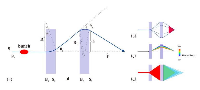
The principle of the proposed beam delivery system, is plotted in Figure 1(a), where the strenghths and lengths of the two magnets in the system are denoted as and , and and , respectively, and they satisfy . We further consider a particle beam with an initial longitudinal momentum of and the charge . The deflection angles of the beam through the first and second magnet ( and ) can be roughly estimated as,
| (1) | |||
| (2) |
where represent the Larmor radius and the above equations are valid under the condition of . The transverse displacement of the particle bunch after drifting a longitudinal distance can then be expressed as . Since these two magnets have opposite signs, the bunch, after passing through the second magnet, finally get deflected back to the initial longitudinal axis and the distance between the crossing point and the rear side of the second magnet is , which can be expressed as,
| (3) |
Through Eq. (3), it is evident that in a given beam transport system with fixed magnetic lengths, the value of parameter is uniquely determined by the ratio of the strengths of two magnets, represented as . This relationship delivers three crucial pieces of information.
Firstly, by scanning () from the positive (negative) maximum to the negative (positive) maximum while keeping their ratio constant, an electron bunch with equivalent energy can be guided towards the same position but along different angular directions. By aggregating these cases, a concentrated dose maximal can be achieved near the converging position where the tumor is located, as shown in Figure 1(b).
Secondly, it is worth noting that Equation (3) is independent of the beam energy. Consequently, electrons with varying energies passing through the system will ultimately converge at the same position. This characteristic implies that the system is remarkably resilient to energy spread, which distinguishes it from other proposed schemes glinec2006radiotherapy , kokurewicz2021experimental , whitmore2021focused (see Figure 1(c)).
Lastly, the focal length can be readily adjusted by modifying the strength ratio , providing exceptional flexibility for targeting tumors at different depths. Figure 1(d) shows three cases of different focal depths.
II.2 Validation using Monte Carlo simulations
In order to validate the proposed scheme, we have performed Monte Carlo simulations using the code TOPAS perl2012topas . In these simulations, we defined the longitudinal direction as , the transverse deflection direction as and the other transverse direction as . The lengths of the two dipoles were set at = 10 cm and = 22 cm, with a separation distance of 30 cm. The maximum strengths of the dipoles were chosen as 1.35 T, with and having opposite signs. Considering an electron bunch originating from a standard laser-wakefield, we set its initial RMS sizes and divergences as = = 4 m and = = 4 mrad, respectively. The bunch had a peak energy of 200 MeV and a 5% RMS energy spread. A water phantom was positioned 30 cm behind the second magnet, with dimensions of 20 cm () 20 cm () 40 cm (), and a voxel size of 1 mm in all directions. The entrance of the water phantom was defined as .
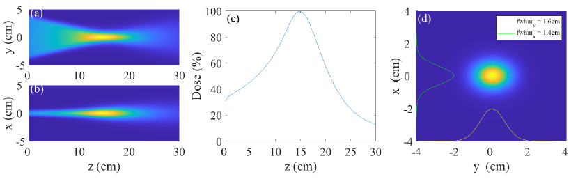
To achieve a large-angle focusing at a specific depth inside the water phantom, we launched eleven simulations. In each simulation, particles were used and we varied only the value of () from the negative (positive) maximum of -1.35 T to the positive (negative) maximum of +1.35 T with a constant incremental step. After summing up all above cases, the resulted dose distribution were presented in Figure 2.
Figures 2(a) and (b) illustrate the central slice distribution in the and planes, respectively, where one can see the appearance of a large-angle focusing effect on the plane, with a maximum dose deposited deep inside the water phantom. To further verify this finding, we present the longitudinal on-axis dose lineout in Figure 2(c). Notably, the dose peak is located at a depth of 15 cm, with the entrance dose only accounting for 33% of the peak dose. Furthermore, Figure 2(d) displays the transverse () dose distribution at the focal point, where the full width at half maximums (FWHMs) along the two dimensions were measured as cm and cm, respectively. These values are comparable to or even smaller than the dose size of a typical proton pencil beam at the same depth, suggesting that the combination of VHEE and this dose delivery system can greatly benefit accurate tumor targeting.
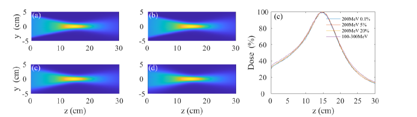
To evaluate the system’s tolerance to the bunch energy spread, we conducted four simulations with the same setup as previously described, but applying electron beams with different energy distributions. The results are presented in Figure 3(a-d). For simulations (a), (b), and (c), the energy spectra adhere to a Gaussian distribution with a central energy of 200 MeV and a RMS spread of 0.1%, 5%, and 20%, respectively. In simulation (d), the energy spectrum is uniform, ranging from 100 MeV to 300 MeV. Despite significant disparities in energy spread, the system is shown to be capable of concentrating the dose peak with similar depths of focus and lateral distributions. Figure 3(e) provides a more detailed on-axis dose distribution along the z-axis for these four cases. The first three cases exhibit negligible differences, with only the fourth case demonstrating minor variation of less than 5%, which confirms the robustness of the system. We should note that the asymmetric focusing effect created by the angular scanning approach can also be achieved using a series of quadrupoles whitmore2021focused . However, to achieve a similar focusing angle (e.g., 35 degrees for a full angle), the required parameters for quadrupoles are much more challenging, and expensive, and they cannot transport electrons with large energy dispersion as effectively as the presented system.
II.3 Controlling the dose peak position
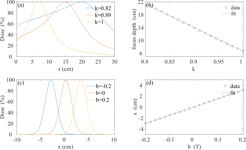
To ensure a precise and flexible dose delivery, a reliable system is necessary to enable the control over the position of dose deposition for targeting different types of tumors. Here we show that by modifying the relationship between two magnetic strengths, this requirement can be fulfilled. We consider a simple relation between them as , where and are controllable variables. This formula allows for the longitudinal (transverse) adjustment of the dose focal position by solely varying (). A series of Monte Carlo simulations have been carried out to confirm this approach with the same setup as Figure 2 but different magnet strengths, and the results are presented in Figure 4. As shown in Figure 4(a), the focal depth inside the water increases from 7 cm to 20 cm as decreases from 1 to 0.82, and the correlation between them is almost linear (see Figure 4(b)). It is noted that this increase in focal depth may result in higher entrance doses owing to increased scattering of electron beams. Figure 4(c) illustrates the transverse dose lineouts along the -axis at the focal depth (15 cm) for different values. By setting to -0.2 T and 0.2 T, the dose focal position can be laterally displaced by 3 cm in the corresponding directions along the -axis, and the transverse displacement is also shown in linear dependence of the values (see Figure 4(d)).
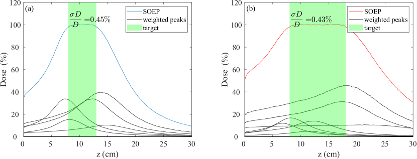
II.4 Flat-top dose peak formation
Similar to the commonly used Spread-Out Bragg Peak (SOBP) technique in proton therapy, which broadens the Bragg peak by linearly superposing different energy spectra, we can also generate a Spread-Out Electron Peak (SOEP) by summing up doses of different focal depths assigned with specific weights. This concept was introduced in whitmore2021focused , and in our case, it can be accomplished by simply modifying the value of the parameter . Figure 5 illustrates two simulation examples of the SOEP for a 200 MeV VHEE beam. In Figure 5(a), a dose plateau extending from a depth of 8 cm to 13 cm is presented, and Figure 5(b) depicts a plateau spanning from a depth of 8 cm to 18 cm. The shaded green region within each figure denotes the desired depth range, where the achieved dose uniformity is quite good, with the relative standard deviations of in Figure 5(a) and in Figure 5(b). Additionally, the grey lines in each figure represent the on-axis doses of different focal depths after applying different weights.
III Conclusion
In this article, we propose a simple dose delivery system that utilizes only two dipole magnets to effectively target deep-seated tumors with a concentrated dose peak. By adjusting the correlations between these two magnets, we can precisely position the dose peak in both the longitudinal and lateral directions. An additional advantage of this system is its resilience to VHEE beams with broadband spectra, which makes it particularly appealing for the use in LWFA. In the future work, we plan to incorporate the proposed system in a rotational gantry based on LWFA, which will compactly deliver doses with precise tumor conformity and high operational flexibility, crucial for the development of VHEE radiotherapy devices towards clinical applications.
References
- [1] S. M. Bentzen, “Radiation therapy: intensity modulated, image guided, biologically optimized and evidence based,” Radiotherapy and Oncology, vol. 77, no. 3, pp. 227–230, 2005.
- [2] C. Elith, S. E. Dempsey, N. Findlay, and H. M. Warren-Forward, “An introduction to the intensity-modulated radiation therapy (imrt) techniques, tomotherapy, and vmat,” Journal of Medical Imaging and Radiation Sciences, vol. 42, no. 1, pp. 37–43, 2011.
- [3] K. Otto, “Volumetric modulated arc therapy: Imrt in a single gantry arc,” Medical physics, vol. 35, no. 1, pp. 310–317, 2008.
- [4] M. Urie, M. Goitein, and M. Wagner, “Compensating for heterogeneities in proton radiation therapy,” Physics in Medicine & Biology, vol. 29, no. 5, p. 553, 1984.
- [5] C. DesRosiers, V. Moskvin, A. F. Bielajew, and L. Papiez, “150-250 mev electron beams in radiation therapy,” Physics in Medicine & Biology, vol. 45, no. 7, p. 1781, 2000.
- [6] M. G. Ronga, M. Cavallone, A. Patriarca, A. M. Leite, P. Loap, V. Favaudon, G. Créhange, and L. De Marzi, “Back to the future: very high-energy electrons (vhees) and their potential application in radiation therapy,” Cancers, vol. 13, no. 19, p. 4942, 2021.
- [7] C. Yeboah and G. Sandison, “Optimized treatment planning for prostate cancer comparing impt, vheet and 15 mv imxt,” Physics in Medicine & Biology, vol. 47, no. 13, p. 2247, 2002.
- [8] T. Fuchs, H. Szymanowski, U. Oelfke, Y. Glinec, C. Rechatin, J. Faure, and V. Malka, “Treatment planning for laser-accelerated very-high energy electrons,” Physics in Medicine & Biology, vol. 54, no. 11, p. 3315, 2009.
- [9] M. Bazalova-Carter, B. Qu, B. Palma, B. Hårdemark, E. Hynning, C. Jensen, P. G. Maxim, and B. W. Loo Jr, “Treatment planning for radiotherapy with very high-energy electron beams and comparison of vhee and vmat plans,” Medical physics, vol. 42, no. 5, pp. 2615–2625, 2015.
- [10] E. Schüler, K. Eriksson, E. Hynning, S. L. Hancock, S. M. Hiniker, M. Bazalova-Carter, T. Wong, Q.-T. Le, B. W. Loo Jr, and P. G. Maxim, “Very high-energy electron (vhee) beams in radiation therapy; treatment plan comparison between vhee, vmat, and ppbs,” Medical physics, vol. 44, no. 6, pp. 2544–2555, 2017.
- [11] G. Zhang, Z. Zhang, W. Gao, and H. Quan, “Treatment planning consideration for very high-energy electron flash radiotherapy,” Physica Medica, vol. 107, p. 102539, 2023.
- [12] A. Lagzda, D. Angal-Kalinin, J. Jones, A. Aitkenhead, K. J. Kirkby, R. MacKay, M. Van Herk, W. Farabolini, S. Zeeshan, and R. M. Jones, “Influence of heterogeneous media on very high energy electron (vhee) dose penetration and a monte carlo-based comparison with existing radiotherapy modalities,” Nuclear Instruments and Methods in Physics Research Section B: Beam Interactions with Materials and Atoms, vol. 482, pp. 70–81, 2020.
- [13] V. Malka, J. Faure, Y. A. Gauduel, E. Lefebvre, A. Rousse, and K. T. Phuoc, “Principles and applications of compact laser–plasma accelerators,” Nature physics, vol. 4, no. 6, pp. 447–453, 2008.
- [14] C. Joshi, S. Corde, and W. Mori, “Perspectives on the generation of electron beams from plasma-based accelerators and their near and long term applications,” Physics of Plasmas, vol. 27, no. 7, 2020.
- [15] E. Esarey, C. B. Schroeder, and W. P. Leemans, “Physics of laser-driven plasma-based electron accelerators,” Reviews of modern physics, vol. 81, no. 3, p. 1229, 2009.
- [16] Y. Glinec, J. Faure, V. Malka, T. Fuchs, H. Szymanowski, and U. Oelfke, “Radiotherapy with laser-plasma accelerators: Monte carlo simulation of dose deposited by an experimental quasimonoenergetic electron beam,” Medical physics, vol. 33, no. 1, pp. 155–162, 2006.
- [17] L. Whitmore, R. I. Mackay, M. Van Herk, J. Jones, and R. Jones, “Focused vhee (very high energy electron) beams and dose delivery for radiotherapy applications,” Scientific Reports, vol. 11, no. 1, pp. 1–14, 2021.
- [18] L. Whitmore, R. Mackay, M. van Herk, P. Korysko, W. Farabolini, A. Malyzhenkov, R. Corsini, and R. M. Jones, “Cern-based experiments and monte carlo simulations on focused vhee (very high energy electron) beams for radiotherapy,” 2023.
- [19] F. Reaz, K. N. Sjobak, E. Malinen, N. F. J. Edin, and E. Adli, “Sharp dose profiles for high precision proton therapy using strongly focused proton beams,” Scientific Reports, vol. 12, no. 1, p. 18919, 2022.
- [20] K. Kokurewicz, E. Brunetti, A. Curcio, D. Gamba, L. Garolfi, A. Gilardi, E. Senes, K. N. Sjobak, W. Farabolini, R. Corsini et al., “An experimental study of focused very high energy electron beams for radiotherapy,” Communications Physics, vol. 4, no. 1, p. 33, 2021.
- [21] K. Svendsen, D. Guenot, J. B. Svensson, K. Petersson, A. Persson, and O. Lundh, “A focused very high energy electron beam for fractionated stereotactic radiotherapy,” Scientific Reports, vol. 11, no. 1, p. 5844, 2021. [Online]. Available: https://doi.org/10.1038/s41598-021-85451-8
- [22] J. Perl, J. Shin, J. Schümann, B. Faddegon, and H. Paganetti, “Topas: An innovative proton monte carlo platform for research and clinical applications,” Medical Physics, vol. 39, no. 11, pp. 6818–6837, 2012.