Presheath-like structures and effusive particle losses for biased probes at and near I-V electron saturation
Abstract
A theory for presheath-like structures near probes biased at and above the plasma potential is developed for collisionless plasmas with an electron-neutral mean free path on the order of the chamber scale. The theory predicts presheath-like perturbations to the plasma that result from the free streaming of electrons and an effusion loss process from the chamber at the electrode. For these situations, a loss-cone-like velocity distribution function for electrons is predicted where the loss angle of the depletion region corresponds to the angular size of the electrode at a specified distance. The angle of the loss cone becomes 180 degrees at the sheath edge. In comparison to a previous collisional electron presheath model that required electrons satisfy a Bohm criterion at the sheath edge [B. Scheiner et al. Phys. Plasmas 22, 123520 (2015)], the present work suggests that no such condition is needed for collisionless low pressure plasmas in the 10 mTorr range. The theory predicts the generation of a density depletion of roughly 0.5 and an electron velocity moment of 10s of percent of the electron thermal speed by the sheath edge in a presheath with a potential drop of less than . The range of this presheath perturbation is determined by the electrode geometry instead of the collisional mean free path. These predictions are tested against previously published particle in cell simulations and are found to be in good agreement.
I Introduction
Langmuir probes are the most common and oldest diagnostic for laboratory plasma experimentsMott-Smith and Langmuir (1926). Their operation is simple: sweep the DC bias of a probe such as a conducting wire or disk electrode and measure the resulting current. The plasma properties inferred from the current-voltage response (c.f. Fig. 1) depend on a theory of how the probe collects ions and retards electrons. Such theory allows one to determine the density, temperature, and electron velocity distribution function (EVDF). The most widely used theories describe the probe-plasma interaction in the electron retarding regime on the basis of orbital motion in a central potentialMott-Smith and Langmuir (1926), electron and ion contribution to space charge in the probe-plasma systemAllen, Boyd, and Reynolds (1957), or both combinedBernstein and Rabinowitz (1959); Laframboise (1966), and have been discussed extensivelyChen (1965). Since most information is gleaned from Langmuir probes operating in this regime little attention has been given to the electron saturation regime (Ref. Medicus, 2004 is one notable exception). This leaves an open question of whether or not useful information can be extracted from the probes under these conditions. This work explores the mechanism of electron collection and the perturbation imposed on the bulk plasma by an electrode in the electron saturation regime in low pressure collisionless plasmas. In doing so we show that the plasma-probe interface is fundamentally different from that which is encountered when the probe is electron retarding or in ion saturation.
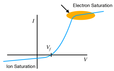
Electron saturation, depicted in the Langmuir probe I-V trace sketch of Fig. 1, occurs when the probe is biased positive relative to the plasma potential such that it is electron collecting. Probes at electron saturation have an electron sheath, an electron rich sheath whose potential increases from the plasma to the probe surface. Until the past decade it was typically assumed that the electron sheath posed little perturbation to the bulk plasma. However, a series of experimental and simulation results published by myself and coauthors showed that at least in some cases the electron sheath is accompanied by a presheath structure that extends into the bulk plasma over a length scale much longer than that of the ion sheathYee et al. (2017); Scheiner et al. (2015, 2016); Baalrud et al. (2020). These measurements used laser collision induced fluorescence to measure 2D profiles of the resulting bulk plasma electron density perturbation in the vicinity of an electron sheath in a 20 mTorr helium plasmaYee et al. (2017). A fluid model developed to explain these observations described the electron presheath as a pressure gradient driven flow of electrons towards the electrode. Other observations predicted by the model and borne out in simulation data included the absence of the presheath potential drop seen in the ion presheathYee et al. (2017); Scheiner et al. (2015), a presheath electron flow velocity with magnitude near the electron thermal speedYee et al. (2017); Scheiner et al. (2015, 2016), and the presence of instabilitiesScheiner et al. (2015) which recently have been observed in experimentsHood et al. (2020).
The most significant prediction of the electron sheath theory was that of an electron sheath Bohm criterion that reguired by the sheath edgeYee et al. (2017); Scheiner et al. (2015). This prediction was based on the premise that the EVDF in the presheath could be approximated as a Maxwellian with a flow shift. However maintenance of a Maxwellian EVDF with a flow shift requires that the presheath be collisional and that its length is significantly longer than the electron mean free path. At the 20 mTorr condition the previous experiments, the observed presheath was similar in length to the cm mean free path. Furthermore, recent experiments at pressures of mTorr measured electron sheath electron fluxes that are consistent with the collection of a random flux and no electron sheath Bohm criterion was indicatedJin et al. (2022). This raises the question of what the proper description is for electron sheaths in low pressure collisionless plasmas.
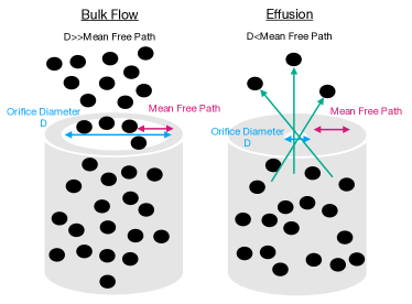
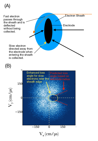
One peculiar observation from collisionless particle-in-cell (PIC) simulations was the formation of a loss cone distribution in the EVDF with the loss region oriented along the normal direction away from the electrode. The angle of this cone decreased, nearly closing to zero, while moving away from the electrodeScheiner et al. (2016). This observation along with the long mean free path of electrons suggest effusion as a mechanism for presheath formation. Effusion (c.f. Fig. 2) is the process by which gas escapes from a container to vacuum through an orifice whose physical dimension is much less than the collisional mean free path. In such cases, particles with free streaming trajectories that pass through the orifice are lost. Contrasting with effusion, when the orifice is much larger than the collisional mean free path the loss from the container to vacuum can be described as bulk fluid flow driven by a pressure gradient. This paper describes the perturbation posed by probes at and near the electron saturation regime as an effusion process.
This paper is organized as follows: Section II presents a theory for effusion based losses starting with the case of a probe biased exactly at the plasma potential in Sec. II.1. This serves as a starting point for the cases of probes biased slightly above and below the plasma potential (Sec. II.2), and the case of the electron presheath at probes biased above the plasma potential(Sec. II.3). In all cases, presheath-like structures are predicted even in cases where the absence of a sheath is predicted. Section III tests the theory against data from previously published 2D PIC simulations. The results are discussed in Sec. IV and a conclusion is given in Sec. V.
II Theory
In this section a theory for boundaries with effusion electron losses is developed. Section II.1 addresses the case where electrons are lost by effusion from a boundary biased exactly at the plasma potential. The theory predicts the EVDF and electron density and flow velocity profiles as a function of position and electrode size. This case serves as a starting point for understanding the behavior throughout the remainder of the paper. Section II.2 discusses specific cases where the electrode is biased less than above or below the plasma potential. Section II.3 considers applications to the electron presheath.
II.1 Boundaries at the plasma potential
We start by considering the form of the plasma-probe boundary when the probe is biased exactly at the plasma potential. Here, it is assumed that no retarding potential is present at the probe for electrons or ions. The theory developed in this section concerns plasmas that are collisionless to the extent that the electron-neutral and electron-electron mean free paths are longer than the length scales of the electron density and flow velocity profiles that are predicted by the theory. It is assumed that particle trajectories are unaffected by any macroscopic electric field and that electrons and ions free stream until they impact the probe boundary. Interaction with other bounding sheaths of the plasma are not considered.
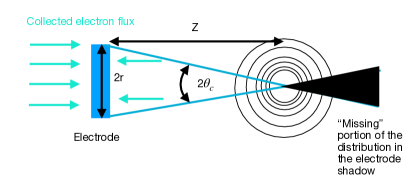
Start with the assumption that electrons move along straight line trajectories until they intercept a conducting boundary at which they are lost from the system. This behavior is analogous to the effusion through the circular orifice depicted in Fig. 2. For the purpose of the present discussion we assume a disk shaped electrode with diameter . As shown in Fig. 3, if one chooses a point some distance away from the disk along a line perpendicular to it’s center, only electrons with velocity magnitude directed within the angle
| (1) |
of the line (oriented in the direction) are collected. Likewise, assuming symmetry between the plasmas on the front and back side of the disk, electrons collected on the backside need to be within an angle of the same magnitude. Electrons with negative z velocity that are not collected move from the plasma on the front side to that on the back, and vice versa, such that electrons in the front side plasma with a velocity magnitude oriented in the positive z direction originated from the back-side plasma. Due to this fact, it is expected that the plasma at point z in front of the electrode is absent of electrons with velocities that are directed within of the direction. In this situation, the EVDF is determined geometrically and is
| (2) |
Here, is the electron density in the plasma as such that , is the electron thermal speed, is the Heaviside function, and . It is worthwhile to note that the arguments above also apply to a position along a non-perpendicular line through the center of an electrode. In this case the electrode radius would be reduced by a factor of , where is the angle between the normal and the line in consideration.
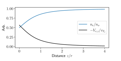
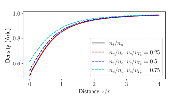
The electron density and z flow velocity profiles can be determined by taking the and moments of the distribution function in Eq. 2. These are
| (3) |
and
| (4) |
The profiles of electron density and flow velocity corresponding to these profiles are shown in Fig. 4. The key feature of these profiles is that the scale length of the perturbation imposed by the probe upon the bulk plasma is comparable to and dependent on the dimension of the electrode disk radius. For the case of the disk electrode this significantly exceeds the length scale of the sheath in many laboratory plasmas for a centimeter scale radius. For reference, the Debye length for a plasma with eV and is 0.033 cm. Electrodes biased at or above the plasma potential that are significantly larger than this scale are expected to perturb the surrounding plasma.
So far, only properties of electrons have been considered. For the present case of a probe biased at the plasma potential, one would expect the ion density to also be described by Eq. 3. On the other hand, the ion velocity would be
| (5) |
Since , the plasma remains quasi-neutral to the boundary, despite the density rarefaction. However, Eqs. 4 and 5 imply that the ratio of the electron to ion flux at each point in the profile including the probe surface is , just as it is through any plane defined in the bulk plasma in the absence of a boundary. If a sheath is not present to balance these loses, how can this be? The answer lies in the requirement that a probe be small compared to the other loss areas of the plasma (e.g. chamber walls) for it to be biased at or above the plasma potential, allowing it to collect more electrons than ions. If the probe is too large the plasma potential will always be above that of the surfaceBaalrud, Hershkowitz, and Longmier (2007).
II.2 Biases near the plasma potential
In this subsection, the situation where the bias is near but not equal to the plasma potential is considered. First we start with the case where the electrode bias is below the plasma potential by an amount that is not more than . This criteria is chosen such that there is a retarding potential for electrons, but not to an extent that nearly all electrode directed electrons are repelled. The validity of this restriction will be evaluated a posteriori. In this case the electron number density is made up of two components. The first term is the loss cone depleted distribution described by Eq. 3 while the second is the portion of electrons within the loss cone () that are repelled by the potential. These components are
| (6) | ||||
where is the velocity at which an electron has energy equal to the retarding potential . The full result is
| (7) | ||||
From this expression it is clear that the amount by which the electron density is decreased is a function of .
Figure 5 shows a comparison of profiles of for , , and with the ion density profile given by Eq. 3: . The most notable feature of the comparison is that for retarding potentials of the electron and ion densities are nearly equal and that quasineutrality can be maintained up to the electrode. This suggests the absence of an ion sheath at the electrode for these conditions. The absence of an ion sheath or presheath electric field justifies the use of the free streaming trajectory assumption.
Now consider the analogous situation with the electrode biased positive with a slight retarding potential for ions. For this case, the electron and ion subscripts on the density equations, thermal speeds, and mass in are interchanged. The conclusion is similar: if the potential is not more than above the plasma potential quasineutrality can be maintained. Since in most laboratory low temperature plasma experiments, there is asymmetric behavior for positive and negative biases about the plasma potential. If for example we consider an electron temperature of eV and an ion temperature of eV, a bias of -0.25V below the plasma potential results in the absence of a sheath, while a bias 0.25 above the plasma potential is sufficient for the formation of an electron sheath. This behavior has been confirmed in PIC simulations with conditions very close to those used in this exampleScheiner et al. (2016).
II.3 Electron Presheath
In this subsection the behavior of the electron presheath is considered. As mentioned in the introduction, the electron presheath is an extended quasineutral region outside of an electron sheath in which the plasma density and electron flow velocity are perturbed from their bulk plasma values. Here the predicted properties of the electron presheath are based on the ansatz that the electrons are collected at the electron sheath edge by the same effusion process as in the case of a probe biased at the plasma potential (Sec. II.1).
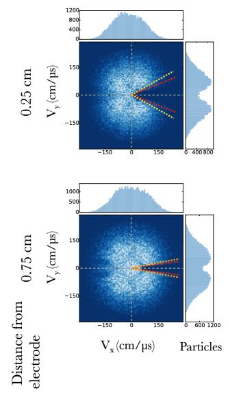
As shown in Fig. 6(A), there is the complication that not all electrons passing the sheath edge are collected by the electrode. Generally, whether or not an electron crossing the sheath edge is collected is a function of its energy, direction, and location relative to the electrode. For example, those crossing the sheath edge near the electrode center are very likely to be collected, while those crossing the sheath edge at a radial distance past the edge of the electrode have an enhanced likelihood of passing through. Likewise, slow electrons passing the sheath edge at a radial location past the edge of the electrode are likely to be collected while fast electrons may not be depending on the orientation of their velocity vector. Figure 6(B) demonstrates a realization of these effects in an annotated EVDF extracted 0.25 cm from a cm electrode in the PIC simulation of Ref. Scheiner et al., 2016. The geometric loss cone angle marked by the red line is enhanced at slow velocities. As indicated by the yellow circle, enhanced collection occurs for slow electrons. These effects act to enhance the effusion loss area for electrons from the bulk plasma. Furthermore, electron deflection by the sheath acts to enhance the positive velocity portions of the EVDF that are just outside of the depletion region. In the limit that the sheath width is small compared to the electrode radius, neither effect is important and the effective value of in the calculation of is the electrode radius. Estimates of the sheath thickness can be made using the Child-Langmuir law for electron sheathsHershkowitz (2005). The presheath properties can be predicted using the theory of Sec. II.1 once the disk radius is replaced by an effective sheath-modified radius . A more detailed theory may treat high and low velocity electrons with different loss angles, but such treatment is beyond the scope of this work.
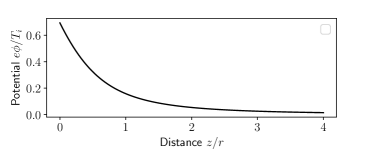
Another point that has gone unmentioned thus far is the value of the electrostatic potential in the electron presheath. If a presheath potential drop of magnitude were present as it is in the ion presheath the free streaming approximation of electron trajectories would break down. However, previous simulations have suggested that the electron presheath electric field is negligible. In fact, the theory provided in this work is consistent with this observation. The potential profile in the presheath can be obtained by assuming a Boltzmann relation for ions and equating the electron density from Eq. 3 with ion density in the presheath to solve for . The potential profile along the axis perpendicular to the electrode center is
| (8) |
The plot of this profile in Fig. 7 indicates that the potential varies by about between the bulk plasma and the absorption surface. For plasmas with , a potential drop of is not enough to appreciably change the electron trajectories in the presheath. When becomes comparable to the presheath electric field will modify the electron trajectories resulting in a breakdown of the free streaming trajectory approximation.
II.3.1 Breakdown of quasineutrality
Here, we briefly consider the breakdown of quasineutrality resulting in the formation of an electron sheath. Expanding the charge density about a point at the sheath edge with potential above the plasma potential, . At this point , but . This requirement is known as the sheath criterionRiemann (1991) and can be restated as
| (9) |
Inserting the derivative of the Boltzmann relation for ions
| (10) |
the derivative of Eq. 3 for electrons
| (11) |
and making use of the quasineutrality relation with Eq. 3 results in
| (12) |
This value is exactly the value obtained by taking the derivative of the presheath potential profile in Eq. 8. Sheath formation results from the presence of an electric field (potential) greater than that of the profile Eq. 8. The maximal probe bias before electron sheath formation is .
III Comparison with prior simulation data
This section tests the predictions of Sec. II.1 and II.3 against existing PIC simulation data from Ref. Scheiner et al., 2016 which were computed using 2D-3V simulations. To compare with simulations, a 2D version of the theory of Sec. II is needed. In 2D PIC, particles in the plane can be viewed as rods with arbitrary out of plane dimension. Therefore, for comparison between theory and simulation, the distribution function and its moments should be defined and computed over their values in 2D since the velocities in the out of plane direction are not affected by the presence of the boundary. The 2D VDF is
| (13) |
where is aligned along the electrode normal. The normalization was determined such that the density moment
| (14) |
yields when . Using this definition, the 2D density profile is
| (15) |
Likewise, the 2D z flow velocity is
| (16) |
which gives
| (17) |
The electrode in the simulations of Ref. Scheiner et al., 2016 is a line segment with length cm. For this the angle subtended by the electrode at distance z is unchanged and the definition of from Sec. II.1 applies.
III.1 Electrode biased at the plasma potential
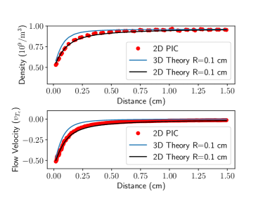
Here we consider the case of the electrode biased at the plasma potential. The theory predicts (1) the loss cone angle of the EVDF and (2) the velocity and density profiles. Starting with (1), we compare the loss cone angle of the EVDF obtained from PIC simulations to the prediction of the angle given by Eq. 1. In Ref. Scheiner et al., 2016, the EVDF was computed at axial distances of 0.05, 0.25, and 0.75 cm from the electrode. For an electrode of diameter 0.2cm, the cone angle for these distances are 63.4o, 21.8o, and 7.6o, respectively. These angles are drawn on the EVDFs in Fig. 8 and are in agreement with the boundary of the depleted region of the distribution. Figure 9 compares the density and flow velocity profiles from the 2D (Eqs. 15 and 17) and 3D (Eqs. 3 and 4) theory with profiles from PIC111Note that the profiles in Ref. 9 were incorrectly normalized by instead of . The correction factor has been applied to the PIC data. The original data from this study is no longer available and data points were extracted from published figures.. The 2D theory provides an excellent description of the simulation data. The 3D theory predicts more shallow profiles and are shown to emphasize the expected difference between 2D and 3D simulations of the same phenomenon.
III.2 Electron presheath
Similar to Sec. III.1, this section makes comparisons for the case of an electron sheath. In the electron sheath simulation, the electrode potential was 25V, the plasma potential was 18.5V, and the sheath edge in the axial direction was approximately 0.18 cm (defined by more than 5% deviation from quasineutrality). First we compare the angle of the loss cone in the presheath with the depletion in the calculated EVDF in Fig. 10. The EVDF was calculated at the same positions as in Sec. III.1, 0.05, 0.25, and 0.75 cm. For the electron sheath simulations only the later two are in the presheath. In the comparison with simulation data we consider the possibility suggested in Sec. II.3 that the thickness of the sheath at the electrode enhances the radius at which electrons are collected. For this purpose we consider an effective electrode loss radius of (unmodified), 0.12, and 0.14 cm. The larger and smaller angle corresponding to cm and 0.1 cm, respectively, are shown and are 21.8 and 29.3 degrees at 0.25 cm and 7.6 and 10.6 degrees at 0.75 cm. Because the larger angle includes some high velocity regions of the EVDF that are not entirely depleted, the angle corresponding to the smaller electrode radius is a better fit for larger electron velocities. As expected from the discussion in Sec. II.3, these electrons have a higher likelihood of passing through the sheath without being collected by the electrode and do not experience enhanced collection.
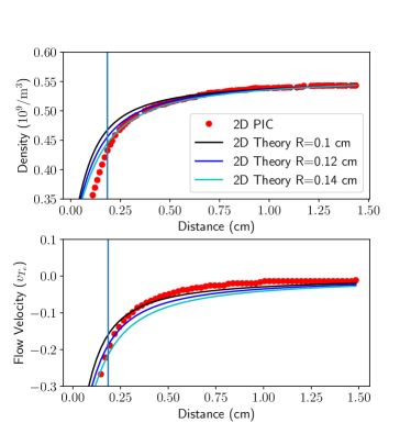
Figure 11 compares presehath density and flow velocity profiles with PIC for the cases of an effective electrode loss radius of , 0.12, and 0.14 cm. Irrespective of the precise value of the electrode radius, the model does a good job of predicting the length scale of profiles seen in the presheath. For the density, small deviations are seen between 0.25 cm and the sheath edge location of 0.18 cm indicated by the vertical line in the figure. The flow velocity profile with cm agrees best with the data, but slightly overestimates the PIC values, being within 50% at 0.8 cm and 20% at 0.5 cm. Finally, the simulations exhibited little change in the electrostatic potential within the presheath, and the value of the electric field term in the previous momentum equation analysis of Ref. Scheiner et al., 2016 was minimal. This is in agreement with the weak potential gradient suggested by Eq. 8.
It is interesting to note that the effects of electron deflection can be observed in the EVDF computed within the sheath in Ref. Scheiner et al., 2016. At locations near and just past the sheath edge, the high velocity regions of the EVDF with positive velocity are populated and the cone angle does not fully reach the 90 degree value at the sheath edge. Inclusion of the effects of a velocity dependent loss cone and electron deflection in the sheath into the model is expected to improve agreement.
IV Discussion
IV.1 Plasma analog of a Knudsen gas
A Knudsen gasKnudsen (1911) is defined as the regime in which particles undergo free molecular flow, colliding more frequently with boundaries than with each other. The extent to which a gas exhibits this behavior is characterized by the Knudsen number , where is the scale of the gas container and is the collisional mean free path. A Knudsen gas satisfies , while a typical fluid has . In this paper a theory for the plasma perturbation posed by probes biased near and above the plasma potential in collisionless plasmas was developed on the basis of the free streaming particle or free molecular flow approximation and effusion loss at a conducting electrode. Contrasting with the case of the ion presheath where ions are accelerated to the Bohm speed by a presheath potentialHershkowitz (2005), the collisionless electron presheath properties are determined only by the loss area of plasma boundaries and electrons do not change velocity otherwise outside of the boundary region. Its properties are determined entirely non-locally by the boundary. In this sense electrons in the vicinity of electrode are a realization of a Knudsen gas.
One limitation of the Knudsen gas analogy is the volumetric source rate of electron in the plasma. In common laboratory DC discharge plasmas, such as those in multi-dipole chambers, electrons and ions are formed at a near constant rate in the chamber volume by electron impact ionization from an energetic primary electron population. For the Knudsen gas description to hold, the phase space of electrons in the vicinity of the electrode should have behavior determined by the collection from the electrode (e.g. absence of certain trajectories due to the formation of the loss cone). If the source rate is too great, the loss cone will fill due to the isotropic sourcing of electrons in the volume. In practice, this may limit the Knudsen gas description to regions within a distance of the boundary. An approximate criteria for this limitation is the ratio of the ionization frequency to the average inverse transit time of an electron to the boundary , where is the mean electron speed. Combined with the Knudsen number requirement, the validity of the Knudsen gas description of electrons requires
| (18) |
An additional limitation of the Knudsen gas description has to do with the growth of kinetic instabilities. Many configurations of the EVDF are possible depending on the electrode geometry. Unstable configurations may result in the growth of waves which may be accompanied by sufficient variations in potential such that the scattering and trapping of electrons may occur. Such effects may result in the change in momenta of electrons in the vicinity of the electrode such that the electron mean free path is shorter than the length scale of the plasma device.
Another related consideration is the anomalous thermalization of the electron VDF known as Langmuir’s ParadoxLangmuir (1925); Gabor, Ash, and Dracott (1955). Langmuir measured a sustained high energy tail in the EVDF even though these electrons had sufficient energy to overcome the sheath potential at the bounding walls of his experiment. The thermalization was unexpected since the collisional mean free path was 5-10 times longer than that which would be needed to explain the observationLangmuir (1925). Different solutions have been put forward, including the electron interaction with standing striations Godyak and Alexandrovich (2015) and an enhanced collision rate for electrons in the presence of instabilitiesBaalrud, Callen, and Hegna (2009). It should be noted that the PIC simulations are capable of modeling an instability enhanced collision rateScheiner and Adrian (2019) and that thermalization was not observed in the simulations that were used to test the theory.
IV.2 Comparison with the previous collisional electron presheath fluid model
The present theory has several similarities with the collisional presheath model in Ref. Scheiner et al., 2015. In this section we contrast the features of the two. In the previous work, the presheath was described by a modified mobility limited flow equation obtained by assuming a Boltzmann relation for ions and inserting a quasineutrality condition into the continuity and momentum equations:
| (19) |
Here, E is the electric field, is the electron mobility determined by the collision and source ionization frequencies, and is the electron Bohm speed. The key features of this model were:
-
1.
The presence of presheath electron flows with velocities approaching the electron thermal speed.
-
2.
A presheath length scale determined by the collisionality or source rate that is much longer that the corresponding ion presheath model () under similar conditions.
-
3.
The presence of pressure gradient driven electron flows.
-
4.
Weak potential gradients with the potential varying by over the presheath length.
In light of the work presented in this paper, such a model is appropriate when either of the quantities from Eq. 18 are much less than unity.
For the collisionless theory several of the key features from the collisional model remain. A flow velocity of is observed in the presheath, roughly 20-30% of the values expected from the collisional theory. In the collisionless case this velocity increases over the length of the presheath which is determined by the size of the electrode, but still may extend a significant distance into the plasma. This length scale is not necessarily longer than that for an ion presheath under similar conditions. When the collisional mean free path is longer than the chamber scale (i.e. ), the ion presheath length becomes half the plasma chamber lengthMeassick, Cho, and Hershkowitz (1985). For both models, minimal potential gradients are present in the presheath due to the ease at which ions are repelled from the boundary, owing to their much lower temperature. Finally, a fluid moment analysis of each theory would indicate the dominance of the pressure gradient term over the potential gradient term in an analysis of the electron momentum balance. In the collisionless case this is purely a non-local effect due to the geometry of the electrode. For the model distribution function in Eq. 2, the derivative of the term of the pressure tensor varies spatially as
| (20) |
This is larger than the corresponding electric field term in the momentum equation calculated from Eq. 8.
For plasmas with the results of neither theory strictly apply. This behavior is analogous to the transitional flow regime in the rarefied gas dynamics literature. This regime is the most difficult to describe because the boundary will induce some amount of non-local behavior in the flow. For these cases, elements in common to both collisional and collisionless theories are expected. A description of this behavior is an open problem and is beyond the scope of the present work.
IV.3 Electron Sheath Bohm Criterion
Prior to the observation of an electron presheathYee et al. (2017); Scheiner et al. (2015, 2016), the conventional wisdom was that the electron flux collected by the electrode is the random flux Hershkowitz (2005); Mott-Smith and Langmuir (1926) and that as a result the electron sheath Bohm criterion is trivially satisfiedRiemann (1991); Chen (2006). Implicit in these statments is that the EVDF at the sheath edge is a half-Maxwellian. The present theory predicts such a half-Maxwellian EVDF and is consistent with the conventional expectations of the collection of the random flux, a result which has been indicated by the recent low pressure experimental observations in Ref. Jin et al., 2022. The presheath predicted in this paper explains how the half-Maxwellian EVDF is generated by the sheath edge and how a presheath can still be present in the absence of a Bohm criterion. The previous prediction of an electron sheath Bohm criterionYee et al. (2017); Scheiner et al. (2015, 2016) applies only to situations where the electron mean free path is much less than the presheath length.
V Conclusion
This paper presents a new theory for an effusion based loss mechanism of electrons for probes biased at electron saturation and near the electron saturation transition. The theory predicts the existence of a presheath with a very weak electric field whose properties are determined non-locally by the electrode geometry and the loss of particles whose free streaming trajectories intercept the conducting boundary. The results were compared with previously published PIC simulations and are in good agreement with density and flow profiles and the predicted EVDF is in good agreement with those from the simulation. Slight deviations that can be attributed to particles passing through the sheath uncollected were observed for the case of the electron presheath. An analogy was drawn between the electrons in the vicinity of the electrode and a Knudsen gas and this comparison was used to demonstrate that the theory requires and weak volume ionization in the gas. The theory was contrasted with the previous collisional electron presheath theory and the range of validity of the collisional and collisionless theory was provided to clarify the situations in which each should be applied. Finally, the theory was found to be consistent with recent low pressure experimental measurements of Ref. Jin et al., 2022 and the conventional wisdom that electron sheath collects a random flux of electrons.
Acknowledgements
The author thanks Louis Jose, Lucas Beving, and Scott Baalrud for their comments on the manuscript. The author also thanks Scott Baalrud for his suggestion of the effusion vs diffusion analogy.
Data Availability
The data that supports the conclusions of this study are contained in the manuscript.
References
- Mott-Smith and Langmuir (1926) H. M. Mott-Smith and I. Langmuir, “The theory of collectors in gaseous discharges,” Phys. Rev. 28, 727–763 (1926).
- Allen, Boyd, and Reynolds (1957) J. E. Allen, R. L. F. Boyd, and P. Reynolds, “The collection of positive ions by a probe immersed in a plasma,” Proceedings of the Physical Society. Section B 70, 297 (1957).
- Bernstein and Rabinowitz (1959) I. B. Bernstein and I. N. Rabinowitz, “Theory of Electrostatic Probes in a Low‐Density Plasma,” The Physics of Fluids 2, 112–121 (1959), https://pubs.aip.org/aip/pfl/article-pdf/2/2/112/12272698/112_1_online.pdf .
- Laframboise (1966) J. G. Laframboise, Theory of spherical and cylindrical Langmuir probes in a collisionless, Maxwellian plasma at rest, Vol. 100 (University of Toronto Toronto, 1966).
- Chen (1965) F. F. Chen, “Electric probes,” in Plasma Diagnostic Techniques, Vol. 21 (Academic Press, 1965).
- Medicus (2004) G. Medicus, “Theory of Electron Collection of Spherical Probes,” Journal of Applied Physics 32, 2512–2520 (2004), https://pubs.aip.org/aip/jap/article-pdf/32/12/2512/7929283/2512_1_online.pdf .
- Yee et al. (2017) B. T. Yee, B. Scheiner, S. D. Baalrud, E. V. Barnat, and M. M. Hopkins, “Electron presheaths: the outsized influence of positive boundaries on plasmas,” Plasma Sources Science and Technology 26, 025009 (2017).
- Scheiner et al. (2015) B. Scheiner, S. D. Baalrud, B. T. Yee, M. M. Hopkins, and E. V. Barnat, “Theory of the electron sheath and presheath,” Physics of Plasmas 22, 123520 (2015), https://pubs.aip.org/aip/pop/article-pdf/doi/10.1063/1.4939024/13976372/123520_1_online.pdf .
- Scheiner et al. (2016) B. Scheiner, S. D. Baalrud, M. M. Hopkins, B. T. Yee, and E. V. Barnat, “Particle-in-cell study of the ion-to-electron sheath transition,” Physics of Plasmas 23, 083510 (2016), https://pubs.aip.org/aip/pop/article-pdf/doi/10.1063/1.4960382/16035562/083510_1_online.pdf .
- Baalrud et al. (2020) S. D. Baalrud, B. Scheiner, B. T. Yee, M. M. Hopkins, and E. Barnat, “Interaction of biased electrodes and plasmas: sheaths, double layers, and fireballs,” Plasma Sources Science and Technology 29, 053001 (2020).
- Hood et al. (2020) R. Hood, S. D. Baalrud, R. L. Merlino, and F. Skiff, “Laser-induced fluorescence measurements of ion fluctuations in electron and ion presheaths,” Physics of Plasmas 27, 053509 (2020), https://pubs.aip.org/aip/pop/article-pdf/doi/10.1063/1.5142014/15879899/053509_1_online.pdf .
- Jin et al. (2022) C. Jin, C.-S. Yip, W. Zhang, D. Jiang, and G.-S. Xu, “Direct measurement of ion and electron flux ratio at their respective sheath-edges and absence of the electron bohm criterion effects,” Plasma Sources Science and Technology 31, 115007 (2022).
- Baalrud, Hershkowitz, and Longmier (2007) S. D. Baalrud, N. Hershkowitz, and B. Longmier, “Global nonambipolar flow: Plasma confinement where all electrons are lost to one boundary and all positive ions to another boundary,” Physics of Plasmas 14, 042109 (2007), https://pubs.aip.org/aip/pop/article-pdf/doi/10.1063/1.2722262/14867320/042109_1_online.pdf .
- Hershkowitz (2005) N. Hershkowitz, “Sheaths: More complicated than you thinka),” Physics of Plasmas 12, 055502 (2005), https://pubs.aip.org/aip/pop/article-pdf/doi/10.1063/1.1887189/13507038/055502_1_online.pdf .
- Riemann (1991) K. U. Riemann, “The bohm criterion and sheath formation,” Journal of Physics D: Applied Physics 24, 493 (1991).
- Note (1) Note that the profiles in Ref. 9 were incorrectly normalized by instead of . The correction factor has been applied to the PIC data. The original data from this study is no longer available and data points were extracted from published figures.
- Knudsen (1911) M. Knudsen, “Die molekulare wärmeleitung der gase und der akkommodationskoeffizient,” Annalen der Physik 339, 593–656 (1911), https://onlinelibrary.wiley.com/doi/pdf/10.1002/andp.19113390402 .
- Langmuir (1925) I. Langmuir, “Scattering of electrons in ionized gases,” Phys. Rev. 26, 585–613 (1925).
- Gabor, Ash, and Dracott (1955) D. Gabor, E. Ash, and D. Dracott, “Langmuir’s paradox,” Nature 176, 916–919 (1955).
- Godyak and Alexandrovich (2015) V. Godyak and B. Alexandrovich, “Langmuir paradox revisited,” Plasma Sources Science and Technology 24, 052001 (2015).
- Baalrud, Callen, and Hegna (2009) S. D. Baalrud, J. D. Callen, and C. C. Hegna, “Instability-enhanced collisional effects and langmuir’s paradox,” Phys. Rev. Lett. 102, 245005 (2009).
- Scheiner and Adrian (2019) B. Scheiner and P. J. Adrian, “Why the particle-in-cell method captures instability enhanced collisions,” Physics of Plasmas 26, 034501 (2019), https://pubs.aip.org/aip/pop/article-pdf/doi/10.1063/1.5089507/15835556/034501_1_online.pdf .
- Meassick, Cho, and Hershkowitz (1985) S. Meassick, M. H. Cho, and N. Hershkowitz, “Measurement of plasma presheath,” IEEE Transactions on Plasma Science 13, 115–119 (1985).
- Chen (2006) F. F. Chen, “Time-varying impedance of the sheath on a probe in an rf plasma,” Plasma Sources Science and Technology 15, 773 (2006).