The influence of thermo-electromechanical coupling on the performance of lead-free BNT-type piezoelectric materials
Abstract
In recent times, there have been notable advancements in haptic technology, particularly in screens found on mobile phones, laptops, LED screens, and control panels. However, it is essential to note that the progress in high-temperature haptic applications is still in the developmental phase. Due to its complex phase and domain structures, lead-free piezoelectric materials such as BNT-based haptic technology behave differently at high temperatures than ambient conditions. Therefore, it is essential to investigate the aspects of thermal management and thermal stability, as temperature plays a vital role in the phase and domain transition of BNT material. A two-dimensional thermo-electromechanical model has been proposed in this study to analyze the thermal stability of BNT material by analyzing the impact of temperature on effective electromechanical properties and mechanical and electric field parameters. However, the thermo-electromechanical modelling of BNT ceramics examines the macroscopic effects of the applied thermal field on mechanical and electric field parameters as phase change and microdomain dynamics are not considered in this model. This study analyzes the impact of thermo-electromechanical coupling on the performance of BNT-type piezoelectric materials compared to conventional electromechanical coupling. The results predicted a significant improvement in piezoelectric response compared to electromechanical coupling due to increased thermoelectric effect in absence of phase change and microdomain switching for temperature boundary conditions below depolarization temperature ( for pure BNT material).
Keywords: Lead-free piezoelectric composites, high-temperature haptic applications, thermo-electromechanical coupling, thermoelectric effects, flexoelectricity, thermal stress.
1 Introduction
Haptic technology has become popular recently in various sensor and actuator applications such as mobile phone screens, laptops, LED screens, and different control panels [1, 2]. These devices work on the sensors that sense the user’s touch, the algorithms that process the data, and the actuators that produce the haptic feedback are all part of the machine side. The neuronal connections that provide information to the brain and the haptic sensors found in the skin make up the human side [3]. Various piezoelectric materials are used in these haptic devices. Piezoelectric materials transform mechanical energy into electrical energy and vice versa [4, 5]. Furthermore, lead Zirconate Titanate (PZT) is used in most piezoelectric applications due to its ease of commercial access and potent piezoelectric response [6]. PZT’s central constituent element is lead, a poisonous chemical detrimental to human health and more prone to environmental contamination [7]. Lead poisoning can lead to renal dysfunction, neural dysfunction, defective reproduction system, weakening of bones and cellular dysfunction in the human body [8]. Furthermore, the level of lead toxicity from PZTs increases with temperature [9]. Therefore, we must consider lead-free piezoelectric material options for haptic technology, especially in high-temperature applications.
Lead-free piezoelectric composites offer scalable and eco-friendly options for electromechanical actuators and mechanical energy harvesting and sensing [6, 10, 11]. These composites typically consist of relatively softer matrices, typically polymers, filled with nano- or micro-particles of hard, crystalline, lead-free piezoelectric materials with vigorous piezoelectric activity, such as non-perovskites like bismuth layered structured ferroelectrics (BLSF) and tungsten bronze ferroelectrics [12], and perovskites like (BT), (BNT), and (KNN) [13, 14, 15]. These lead-free piezoelectric materials have lower piezoelectric coefficients, but their piezoelectric performance may be enhanced by intrinsic (lattice distortions) and extrinsic contributions (altering the domain topologies) [16]. By lattice softening and decreasing unit cell distortion, a novel KNN-based piezoelectric material exhibits a more robust piezoelectric response () and an increased Curie temperature () [17]. In , a remarkably high piezoelectric response of () is produced by controlling the multiphase coexistence of rhombohedral-orthorhombic-tetragonal (R-O-T) and the phase transition temperature [18]. Similarly, 0.94BNT-0.06BT exhibits a 200% improvement in piezoelectric response and enhanced thermal stability (depolarization temperature increases to 57 from 32) by engineering template grain formation utilizing NN templates, which harnessed the microstructure of BNT-based ceramics [19].
However, BNT has a significantly more complicated domain structure than BT and KNN due to its more complex phase structure. Pure BNT has depicted moderate piezoelectric properties () and high coercive electric field () [20]. Pure BNT exhibits rhombohedral R3c, monoclinic Cc, and a mixture of both phases below depolarization temperature () depending on different electrical and mechanical treatments [21, 22]. However, these existing phases exhibit ferroelectric (FE) domain switching and show good piezoelectric properties. Above , BNT exhibits an orthorhombic Pnma phase with an anti-ferroelectric (AFE) character between 200-320℃ [23, 24, 25, 26]. It is supposed to be a nonpolar or weakly-polar phase and exhibits a maximum value of dielectric constant at 320℃ which is called the maximum dielectric temperature (). Above this temperature, BNT exhibits a paraelectric tetragonal P4bm phase till 520℃ and convert to a symmetric cubic Pm3m structure [27], this temperature is designated as Curie temperature () above which piezoelectric effect is negligible due to the symmetric nature of the cubic phase. As a result, regulating these temperatures using various approaches can improve the piezoelectric capabilities of BNT material. Various techniques, including quenching, ceramic composites, binary or ternary solid solutions, and ion replacement, can improve BNT’s domain structure. These strategies primarily influence domain structure, which in turn affects macro performance of BNT-type piezoelectric materials. An adequate selection of oxides for BNT/oxide composites may improve its thermal stability. In , the depolarization temperature has been deferred to higher temperatures (116℃-227℃). The remains stable even at 210℃ [28]. It was also found that the piezoelectric response of 0.94BNT-0.06BT for thick films (285nm) increased with temperature from 1100 to 1160℃. But it decreases at 1180℃ [29]. Considerable strain and ultra-low hysteresis with suitable temperature and frequency stability are achieved simultaneously in BNT-6BT-0.2SLT ceramic to highly dynamic PNRs via pushing relaxor temperature to room temperature by SLT addition to the BNT system [30].
Furthermore, with the inclusion of KNNG composition, and one wt% Gd2O3 demonstrates increased piezoelectric and dielectric capabilities by moving depolarization temperature () and Curie temperature () values towards lower temperatures. According to the findings, ceramics are promising for high-power electromechanical applications [31]. Furthermore, Jaroopam and Jaita [32] reported that adding BMT to BNT increased grain size, dielectric, piezoelectric, ferroelectric, and polarization characteristics owing to increased maximum temperature (). The ferroelectric () and piezoelectric (low-field ) characteristics of the in ceramic were both good. Furthermore, including BMT increased the magnetic properties, energy storage efficacy, and strain generated by electric fields for the ceramic, which was approximately 3.4 times (240%) more effective than the pure BNT ceramic [32]. Mahdi and Majid [33] investigated the effect of polarization in BNT-BKT-BT inclusion on the PVDF matrix in a hot press as a function of volume percent. By increasing the volume percentage from 0 to 0.3, the piezoelectric and pyroelectric coefficients rose from 28 to 40 pC/N and 26 to 95 correspondingly. A stable operating temperature of 150℃ has been achieved by changing the phase structure from R to RT coexisted phase. This is achieved by adding PMN and BST to a non-stoichiometric BNT matrix, making the material more ferroelectric relaxor by lowering the remnant polarization and keeping the maximum polarization [34]. However, Zr-modified BNKT ceramics have been synthesized, and their electromechanical properties are investigated. These results indicate that an appropriate amount of Zr substitution significantly enhances the field-induced strain level of BNKT ceramics, and higher values of piezoelectric constant also increase [35].
Moreover, in quenched BNT-7BT ceramics, this study has been shown to raise the depolarization temperature () by 44 and achieve a temperature-independent throughout a broad temperature range of 25–170 by improving the ferroelectric state connected to the R3c phase [36]. However, adding 1 mol% AlN in BNT raises from 165 to 234 pC/N and increases by 50 due to a rise in the tetragonal phase. Furthermore, with this composition, the modified ceramics have bigger grains and high-density lamellar nano-domains with diameters ranging from 30 to 50 nm. Thus, polarization reversal and domain mobility are greatly amplified, leading to the enormous . Temperature-dependent dielectric and XRD studies indicated that the delayed thermal depolarization in the modified ceramics is due to enhanced and poling-field stabilized tetragonal structure [37]. Furthermore, BF-BT-xBNT at exhibits the best piezoelectric constant with . It is produced in the sample due to the synergy effect of optimal R/T phase ratio, enhanced tetragonality, increased density, and decreased leakage current [38].
Based on the aforementioned research, it can be inferred that optimizing temperature management and thermal stability is crucial in improving the piezoelectric properties of BNT and its substitute ceramics. Hence, it is imperative to conduct a comprehensive investigation on the piezoelectric properties of BNT under varying thermal circumstances since the material’s behaviour manifests distinct phases and domain structures at different temperature levels. Most existing research on the investigating the thermo-electromechanical behaviour of BNT materials is primarily experimental. However, there is a need for more literature that specifically addresses the numerical coupling of thermo-electromechanical phenomena. Numerical studies have significant importance due to their cheap processing cost and ability to accurately anticipate behaviour that closely aligns with experimental observations. Experiments that are challenging to conduct can be readily substituted by numerical simulations. There is a limited amount of research available on the topic of thermo-electromechanical coupling. While some studies have been undertaken on electromechanical coupling [39, 40, 41], it remains challenging to comprehend the thermal stability and temperature regulation using this type of modelling. Consequently, it is crucial to investigate the thermo-electromechanical coupling of BNT material in order to anticipate its behaviour under elevated temperatures. The BNT material has intricate phase and domain structures, demonstrating heightened complexity with increasing temperature. The investigation of phase changes is vital for the advancement of high-temperature haptic applications. Nevertheless, considering the intricate and extensive body of research pertaining to the domain structure of ceramics based on BNT (bismuth sodium titanate), our focus will be directed towards the alterations occurring in the nano-domain as a result of external stimuli such as composition, electric field, and temperature. Additionally, we will examine the impact of these changes on the strain properties at the macro-level and the fatigue behaviour of BNT-based ceramics. Therefore, the primary objective of this study is to investigate the thermo-electromechanical modelling of BNT ceramics, explicitly examining the macroscopic impacts of phase changes on mechanical and electric field parameters. However, the detailed modelling of domain switching and the coexistence of phases are areas for further exploration in this study.
2 Mathematical model
The steady-state behaviour of a two-dimensional piezoelectric composite architecture comprised of microscale piezoelectric inclusions (BNT) is investigated. The sub-sections that follow will go over the composite architecture, the coupled thermo-piezoelectric model that was used to study the composite’s behaviour, the materials models that govern the dielectric and mechanical properties of the composite, and the boundary conditions that were used to compute specific effective electro-elastic coefficients of interest.
2.1 Geometrical description of piezoelectric composite and inclusions
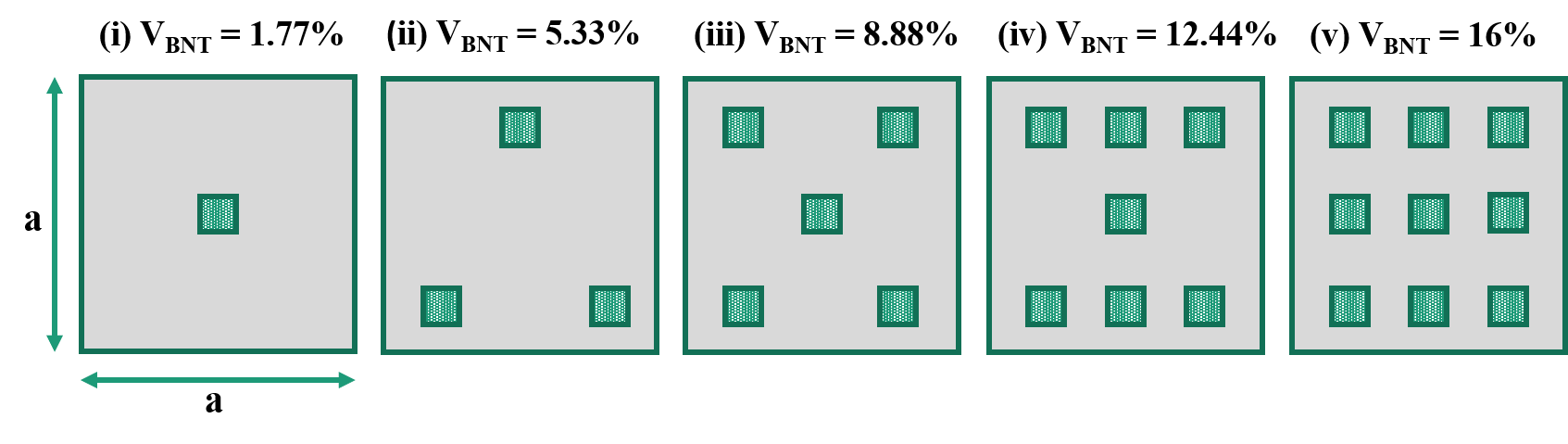
As illustrated schematically in Fig.1, we represent the composite as a two-dimensional RVE in the plane. The composite comprises two parts: (i) the rectangular matrix with and dimensions, and (ii) microscale polycrystalline lead-free BNT inclusions square shaped were included. The piezoelectric inclusions are around 20 μm in size, while the sides ( and ) of exemplified RVE geometry are 150 μm long. The geometric description is inspired by the work of Krishnaswamy et al. [42], who investigated same-sized matrix geometry with a similar amount of BaTiO3 material inclusions. However, they used random size inclusions, but we used squared shape BNT inclusions; thus, the volume fraction is somewhat different for the same number of inclusions. The volume fraction of BNT inclusions is dependent on the number of inclusions, which is better described in Fig.1. The length scale of piezoelectric inclusions is microscopic, while the length scale of the grain size is of nano-range. Therefore, the consideration that must be taken into account is that the size of the inclusions must be greater than the optimal grain size of the composite to get enhanced piezoelectricity in the poly-crystal of BNT.
2.2 Coupled thermo-electromechanical model for piezoelectric composites
The preceding section describes the composite geometry being examined in this work. We describe the thermo-electromechanical model that was used to investigate the composite design described in section 2.1 and schematically depicted in Fig.1. In the context of the linear theory, the Helmholtz free energy function considering three independent variables of our system has been of the following form [43]:
| (1) | |||||
where are the elastic constants, are the dielectric constants, are the piezoelectric constants, are the flexoelectric constants, are the thermal modulus, is the thermoelectric constants, and are heat capacity coefficients respectively. The heat capacity coefficients are defined as where is the heat capacity at constant volume and elastic strain at ambient temperature . The constitutive relationships for thermo-electro-mechanical coupling are derived from Eq.1 and are as follows [44]:
| (2) |
| (3) |
| (4) |
| (5) |
where is the entropy and is the temperature difference. The and are the elastic stress and strain tensor components, respectively, whereas are the electric flux density vector components, and are the electric field vector components. Further, the governing equations that provide equilibrium to all applied fields are as follows [44, 45]:
| (6) |
| (7) |
| (8) |
where denotes the components of body force expected to diminish. In the absence of higher-order stress components , Eq.6 would reduce to linear momentum balance in the traditional elastic formalism. The higher-order stresses may be read as moment stresses, and the balance equation can be conceived as incorporating the balance for linear and angular momentum. Eq.8 becomes a simple steady-state heat conduction equation without heat generation term .
The gradient equations correspond to the relationships between the linear strain and mechanical displacement, the electric field and electric potential, and the thermal field and temperature change. They are stated respectively as [5, 44]:
| (9) |
| (10) |
| (11) |
where , , , , , , and are the components of the strain tensor, electric field vector, thermal field vector, mechanical displacement vector, electric potential, thermal conductivity and temperature change from the reference, respectively.
2.3 Piezoelectric response of composites and boundary conditions
The previous sections described the features of the composite geometry explored here and the coupled equations that regulate the composite’s piezoelectric and thermoelectric behaviour. We compute the effective and of the composite to evaluate its piezoelectric response. These effective coefficients must be determined using two independent boundary conditions that apply axial strains along the and directions BC1 and BC 2, as described in Fig. 2(a) and 2(b), respectively.
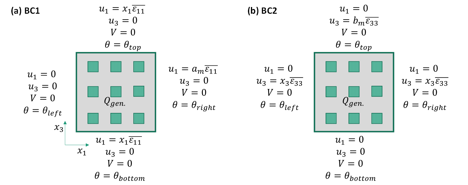
These two different mechanical boundary conditions are analyzed for different thermal BCs, as other thermal conditions can have different thermo-elastic and thermoelectric behaviour. The different types of thermal boundary conditions for BC1 and BC2 are as follows:
-
•
One side heating:
-
–
(a) BC1: , ,
-
–
(b) BC2: , , and for both BC1 and BC2.
-
–
-
•
Two side heating:
-
–
(a) Adjacent wall heating: , and for both BC1 and BC2.
-
–
(b) Opposite wall heating:
-
*
(a) BC1:, ,
-
*
(b) BC2: ϑ_{top} = , , and for both BC1 and BC2.
-
*
-
–
-
•
Three side heating:
-
–
(a) BC1: , ,
-
–
(b) BC2: , , and for both BC1 and BC2.
-
–
-
•
All side heating: , and for both BC1 and BC2.
-
•
Internal heat generation: , and for both BC1 and BC2.
Using boundary conditions BC1, we determine the composite’s effective characteristics ,, and and, using the second set of boundary conditions BC2, we determine the effective characteristics , , and of the composites. The Voigt notation is used to convert four- and three-digit indices of elastic coefficients, and piezoelectric coefficients into two-index notation for simplifying the notation system and reducing the number of variables to reduce the computational cost. The volume average of quantity is denoted as in the following calculation. It is computed as [4, 46]:
| (12) |
Where Ω is the volume across which the integration is performed, the complete volume of the RVE in this example. The following volume averages are derived by applying the boundary criteria BC1 [4, 46] where the applied axial strain in the x-axis is equal to the average axial strain in the x-axis, while the applied axial strain in the y-axis and the applied transverse strain is zero. Also, the applied electric field in the poling axis (y-axis) is zero, as shown in Eq. 13:
| (13) |
| =, | (14) |
where is the volume average of the electric flux density vector’s component. Similarly, using the second set of boundary conditions BC2, the volume averages shown below are produced [4, 46] where the applied axial strain in the y-axis is equal to the average axial strain in the y-axis, while the applied axial strain in the x-axis and the applied transverse strain is zero. Also, the applied electric field in the poling axis (y-axis) is zero, as shown in Eq.15:
| (15) |
| =, | (16) |
We assume the development of minor values of axial stresses inside composites due to applied axial strains in our computations and set and in BC1 and BC2, respectively, to . The finite element analysis, performed using COMSOL Multiphysics software, analyzes the behaviour of the composites based on the thermo-electromechanical model and the boundary conditions placed on the geometrically tailored composite architecture.
2.4 Material Properties
For our investigation, we settled on polydimethylsiloxane (PDMS), a soft polymer matrix. The literature has been paying more and more attention to experimental efforts to create piezoelectric composites with soft matrices through 3D printing and other cutting-edge technologies. These soft matrices provide two challenges, however. Initially, the applied mechanical stimuli from the BNT are screened by their smooth elastic characteristics, which leads to a relatively minimal production of electric flux. Second, the passage of electric change out of the piezoelectric inclusions needs to be improved by the typical weakness of polymeric materials such as dielectrics. Nonetheless, other tests, including recent initiatives in these areas, suggest that getting around both problems above is possible. Based on these experimental findings, a soft matrix, represented by PDMS in this instance, is a prime choice for assessing the potential for elastic and dielectric enhancements to increase the piezoelectric response. The material constants of the PDMS matrix and BNT inclusions for which computations have been performed are compiled in Table 1. Analysis of the thermal stability and degradation of polymeric composites based on PDMS is a crucial problem which should be examined for higher temperatures.
| Material Property | Values of BNT | Values of PDMS Matrix [47] |
| Elastic coefficients (GPa): | ||
| 153.9 [48] | ||
| 52.1 [48] | ||
| 168.1 [48] | ||
| 82.3 [48] | ||
| Young’s Modulus () | 93.0 [49] | 0.002 |
| Poisson’s Ratio () | 0.23 [49] | 0.499 |
| Relative permittivity: | ||
| 367 [50] | 2.72 | |
| 343 [50] | 2.72 | |
| Piezoelectric coefficients : | ||
| 87.3 [48] | Non-piezoelectric | |
| -15.0 [48] | ||
| 72.9 [48] | ||
| Flexoelectric coefficients : | ||
| , longitudinal | [48] | |
| , transverse | [48] | |
| , shear | 0 [48] | 0 |
| Thermo-elastic coefficients: | ||
| .[51] | 3. | |
| Thermoelectric coefficient: | ||
| [29]. | Non-thermoelectric | |
| Heat capacity coefficient: | ||
| 500 [29]. | 1460 |
3 Results and discussions
3.1 Effects of thermal boundary conditions on mechanical field
The mechanical domain is influenced by the implementation of thermal boundary conditions, resulting in the emergence of thermal stress and strain. These factors subsequently induce modifications in a range of mechanical and elastic characteristics. The creation of heat stress is impacting the effective directional elastic coefficients. In addition, heat stress and strain impact both the primary and transverse mechanical strain. Furthermore, it should be noted that the arrangement of piezoelectric inclusions has a significant effect on specific mechanical characteristics, including primary and transverse strain. The amplitude and distribution of thermal stress and strain are influenced by several types of thermal boundary conditions, including one-side heating, two-side heating, three-side heating, all-side heating, and internal heat generation.
3.1.1 Effects of thermal boundary conditions on mechanical field
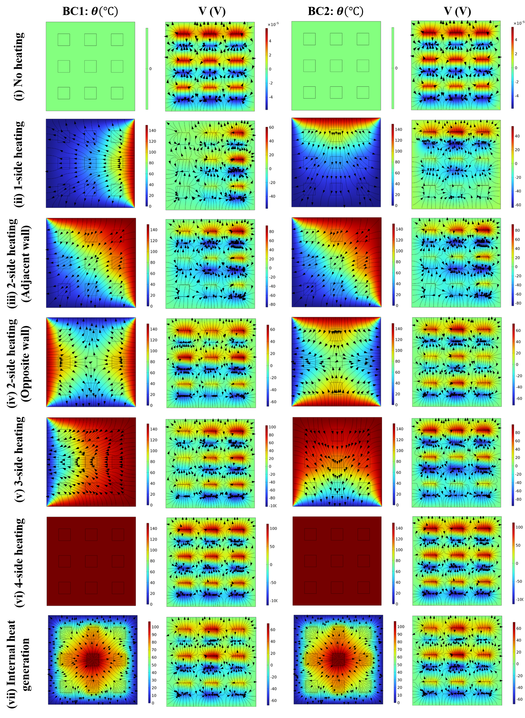
The piezoelectric-PDMS matrix will respond differently depending on the temperature and mechanical boundary conditions. The thermal field will alter the mechanical field due to the development of thermal stresses and strains, which will also affect the piezoelectric performance of the materials. Changing the amplitude and direction of the thermal boundaries will influence the heat transfer rate and temperature distribution. Furthermore, changes in the number of thermal constraints will affect the mechanical field. As a result, research into the mechanical behaviour of BNT-based piezoelectric composites at various thermal boundary conditions is urgently needed. Fig. 3 depicts the temperature and strain distribution contours in the different boundary conditions. The heat transfer lines are positioned on the temperature distribution curve, indicating the direction of heat transfer and heat flow in the matrix and the inclusions. When these lines travel into inclusions, their slope gets steeper. As a result, the heat transmission rate in inclusions is more significant than in the matrix, and the temperature gradient is reduced, resulting in a relatively uniform temperature within the inclusions. However, the temperature gradient in the matrix and piezo-inclusions in the direction of heat transport may be visualized, which will govern the creation of thermal stresses and strains in the composite. Since the distribution of inclusions inside the composite varies with volume fraction, and both inclusions and matrix display distinct mechanical properties, the stress and strain distributions will be influenced by inclusion orientation in the composite.
As illustrated in Fig. 3(i), the strain distribution relies purely on mechanical stress until there is no external or internal heating of the geometry. The strain is equally distributed throughout the BNT-based piezoelectric composite and only reaches high values at the boundary corner when mechanical force is applied. The use of thermal boundary conditions increased the amount of the strain owing to thermal strain induction, which will help mechanical strain in the direction of the applied load. In Fig. 3(ii), the geometry is heated on one side, and a thermal boundary condition is imposed on the exact boundary where mechanical loading is applied. At the same time, all other boundaries remain at ambient temperature. The thermal boundary can expand in response to applied mechanical and thermal loading, whereas the opposite edge to the applied thermal boundary is restricted to any displacement or size change. As a result, it is evident that the thermal strain is most significant close to the thermal border and diminishes in all other directions in proportion to the decrease in temperature gradient. Because the piezoelectric inclusions have smaller dimensions, lower temperature gradients, and more robust elastic characteristics than the matrix, their strain distribution is more uniform. Since the wall across from it is immovable, compressive thermal stress is generated close to it, causing negative strain in this area. Using the thermal boundary condition boosted strain production inside the matrix and the piezoelectric effect along the inclusions, as explained further in section 3.2 of the study. As a result, increasing the heat strain benefits piezoelectric behaviour until the material breaks mechanically.
Increasing the thermal boundaries improve the strain even further. In this situation, the wall with mechanical loading and its neighbouring wall is heated, while the other two walls remain at ambient temperature (see Fig. 3(iii)). The amount and distribution of thermal strain grow as the high-temperature zone spreads. Maximum thermal strain is detected at the boundary where mechanical loading is applied, whereas higher compressive strain is recorded in the region of the mechanically constrained border. The propagation of longitudinal stresses is reduced from mechanical loading borders to mechanical constraint boundaries. The temperature distribution is such that thermal stress affects the longitudinal and transverse strains, resulting in the strain distribution pattern seen above. The thermal strain at the neighbouring wall was expected to be larger; however, the result is similar due to the production of compressive stresses.
Furthermore, the BNT-type piezoelectric composite is investigated for two opposite wall heating sides, which display a distinct strain distribution pattern, as illustrated in Fig. 3 (iv). The mechanical loading and constraint borders are subjected to thermal boundary conditions, while the other two walls remain at room temperature. Inside the geometry, the strain distribution follows the temperature distribution. The heat transfer direction is from heated walls to cold walls, and it is evident that heat transmission at the geometry’s core is zero.
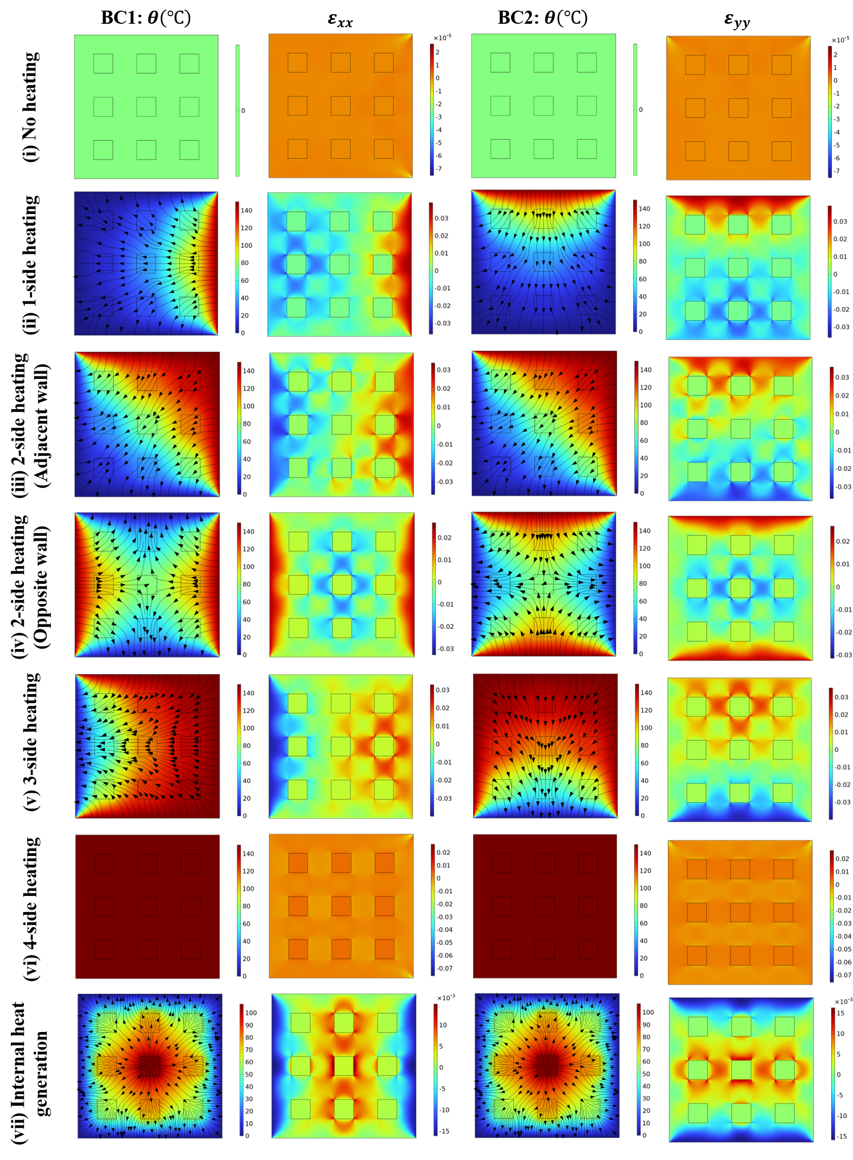
Similarly, the longitudinal strain distribution is excellent at mechanical loading and limited boundaries. It decreases as we travel away from the walls owing to thermal strain formation, and the centre of geometry is dictated by compressive strain caused by thermal stress. However, the strain distribution for all piezo-inclusions is approximately uniform in this type of thermal loading, which can be a good factor for a uniform piezoelectric response. However, with this thermal loading, the strain distribution for all piezo-inclusions is nearly uniform, which might be a beneficial factor for consistent piezoelectric response.
Increasing the number of thermal barriers to three further spreads the thermal strain distribution, as illustrated in Fig. 3 (v). In this circumstance, all three walls except the mechanical constraint boundary are heated, and heat transfer is from these three walls to the mechanical constraint border. As a result of the mechanical strain generated by compressive thermal stress, the strain distribution is highest at the mechanical loading boundary. It decreases in all other directions, becoming negative in the proximity of the mechanically constraint boundary. However, under these types of thermal settings, the spread of thermal strain has been enhanced further and is determined by temperature dispersion inside the geometry. Furthermore, the number of thermal barriers has been extended to four in Fig. 3 (vi), and it is discovered that no temperature gradient is noticed inside the geometry. However, the temperature of the entire geometry rises due to heating. Across the whole geometry, a uniform yet increased strain distribution was observed. Only strain fluctuation at the corners of the mechanical loading boundary is noticed, which is caused by mechanical load. The strain elevation is caused by thermal pressure created by all side heating, and thermal stress creation is low since the temperature gradient is slight in the geometry. Uniform thermal strain distribution also implies that displacement owing to temperature rise is constant in all directions, implying that displacement variance is attributable only to mechanical stress. The whole composite is designed to have the same piezoelectric response across all inclusions, although this might vary owing to mechanical loading.
We have previously investigated the influence of non-uniform and uniform external heating on the BNT-based piezoelectric composite, and it has been discovered that a rise in thermal barriers increases the spread of thermal strain distribution inside the composite, which becomes uniform in the case of constant heating. This is believed to improve piezoelectric performance; however, the emphasis on internal heat production in the mechanical field needs to be thoroughly examined, as deduced from Fig. 3 (vii). All boundaries are held at room temperature, and each piezoelectric inclusion undergoes internal heat production. The heat transmission is uniformly spreading outwards from the source to the walls, and the temperature distribution is identical, more significant in the centre and decreasing uniformly towards the wall; nevertheless, heat creation from each inclusion raises the temperature at that specific place. The strain distribution is also the same, with a maximum in the centre and a decrease towards the wall. However, compressive mechanical strain is detected near the mechanical constraint and loading border. The most essential aspect is that all inclusions are subjected to increased thermal strain, which is expected to improve piezoelectric performance.
It can be assumed that external or internal heating will favourably impact the mechanical field and cause increased longitudinal strain, which will aid in obtaining an improved piezoelectric response. However, consistent heating on all sides provides a uniform, improved mechanical field, which is advantageous in upgrading uniform piezoelectric response.
3.1.2 Effects of thermal boundary conditions on effective elastic coefficients of materials:
The calculation of effective elastic coefficients is based on Eqs. 14 and 16, which demonstrate that these coefficients are exclusively determined by the major plane stresses. These stresses, in turn, are influenced by the thermal stresses that are created. The thermal compressive stresses are generated solely in principal planes as a result of heating. Consequently, the impact of this phenomenon on the effective elastic coefficients of the material is observed in a similar manner. The effective elastic coefficients and in the principal directions are influenced by compressive stress. However, the effective elastic coefficient is also affected by temperature boundary conditions as is defined as the ratio of the average principal stress in one direction to the average principal strain in the other direction. The thermal compressive stress is the primary contributing factor to the variation of the principal stress and effective elastic coefficients. Fig. 4 (i) illustrates the relationship between temperature and the fluctuation of effective elastic coefficients in the case of one-side heating. In the absence of heating, the effective elastic coefficients exhibit a positive behaviour attributed to mechanical constraints, resulting in a rise in their values with an increasing volume percentage of piezoelectric inclusions. As the temperature rises, the dominance of thermal compressive stresses over tensile mechanical stress increases, leading to negative values for the overall effective elastic coefficients. The influence of the volume fraction becomes negligible for the effective elastic coefficients , , and due to the compensatory effect of thermal compressive stress in both principal planes, which counteracts the rise in tensile stress resulting from mechanical constraint. However, the average strain in both primary directions is essentially equal due to identical thermal and mechanical boundary conditions. Furthermore, the elastic and thermo-elastic properties of BNT in these principal directions demonstrate a close resemblance, respectively. The BNT possesses similar elastic and thermo-elastic characteristics in their primary directions, is subjected to similar mechanical and thermal boundary conditions, and will experience comparable mechanical and thermal stresses, respectively. As a result, the net average strain in both directions displays minimal disparity. This observation is supported by Fig. 4 (i), which indicates that all effective coefficients demonstrate comparable trends as the wall temperature increases. Additionally, the influence of increasing volume fraction and distribution of inclusions becomes negligible under thermal loading conditions, as the change in effective coefficients with volume fraction is minimal.
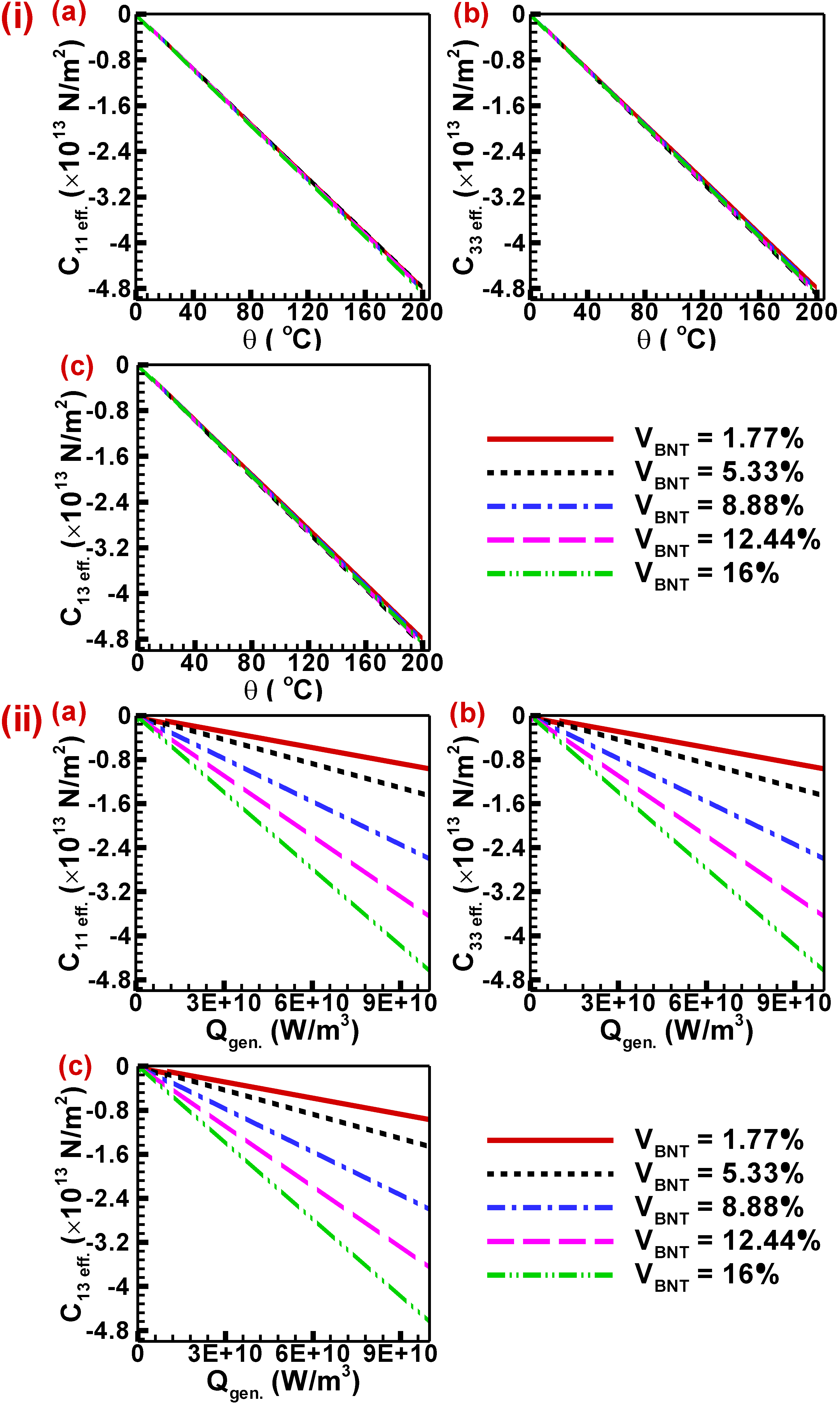
Furthermore, the relationship between effective elastic coefficients and internal heat production is depicted in Fig. 4 (ii). At the outset, the effective elastic coefficients exhibit positive values without any thermal boundary conditions. The presence of internal heat generation leads to the development of thermal compressive stress in the region of a piezoelectric inclusion. This stress has the effect of reducing the effective elastic coefficients. The effective elastic coefficients have greater negative values due to the dominance of thermal compression stress over mechanical tensile stress. All elastic coefficients display a similar pattern, as they are all determined by the primary stresses and strains, as defined in Eqs. 14 and 16. The thermal compressive stress is dependent on the volume percentage of piezoelectric inclusions as a result of internal heat production inside the BNT-type piezoelectric material. In instances where there is internal heat generation, the thermal compressive stress experiences a rise in magnitude as the volume portion also increases. Consequently, the effective elastic coefficients exhibit an upward trend in negative values with the escalation of the volume % of piezo-inclusions. Moreover, the negative values of elastic coefficients become more pronounced when internal heat generation increases due to the corresponding rise in temperature and the resulting thermal compressive stress. The relationship between effective elastic coefficients and heating is consistent in both internal and external heating scenarios. However, the relationship between effective elastic coefficients and volume fraction differs between the two scenarios. This difference arises from the fact that each piezo-inclusion is individually heated in the internal heating scenario, but in the external heating scenario, this is not the case.
Further, Fig. 5 (i) illustrates the relationship between the effective elastic coefficients and the growing number of thermal boundaries. The statement suggests that a growing number of boundaries refers to the expansion of the boundaries where thermal boundary conditions are being implemented. A value of 0 indicates the absence of heating, signifying the presence of electromechanical coupling exclusively. On the other hand, values of 1, 2, 3, and 4 correspond to one-side heating, two-side heating, three-side heating, and all-side heating, respectively. It is evident that the effective elastic coefficient demonstrates positive values in the absence of heating, as it is subjected solely to tensile mechanical stress. Furthermore, these values indicate an upward trend with the augmentation of the volume fraction of BNT inclusions. However, the inclusion of thermal boundary conditions on a single boundary, namely one-side heating, results in the generation of thermal stress (compressive in nature) that exceeds the mechanical tensile stress. As a consequence, the effective elastic coefficients exhibit negative values. The significance of increasing the volume fraction diminishes as it leads to an increase in the magnitude of tensile stress created. Simultaneously, there is a proportional rise in thermal compressive stress, resulting in roughly equivalent and negative values of effective elastic coefficients. Furthermore, the augmentation of thermal barriers results in a heightened magnitude of thermal stress. Consequently, the net principal stress becomes more compressive, leading to a rise in its negative value. This finding suggests that the effective elastic coefficients have a greater magnitude of negative values as the temperature bounds grow, and this relationship follows a linear trend. The significance of increasing the volume fraction diminishes as it leads to an increase in the magnitude of produced tensile stress. Simultaneously, there is a proportional rise in thermal compressive stress, resulting in roughly equivalent and negative values of effective elastic coefficients. Furthermore, the amplification of thermal stress is observed when the number of thermal boundaries is increased. This results in a greater compressive net principal stress, leading to a rise in its negative value. This suggests that the effective elastic coefficients have a greater magnitude of negative values as the temperature bounds grow, and this relationship follows a linear trend.
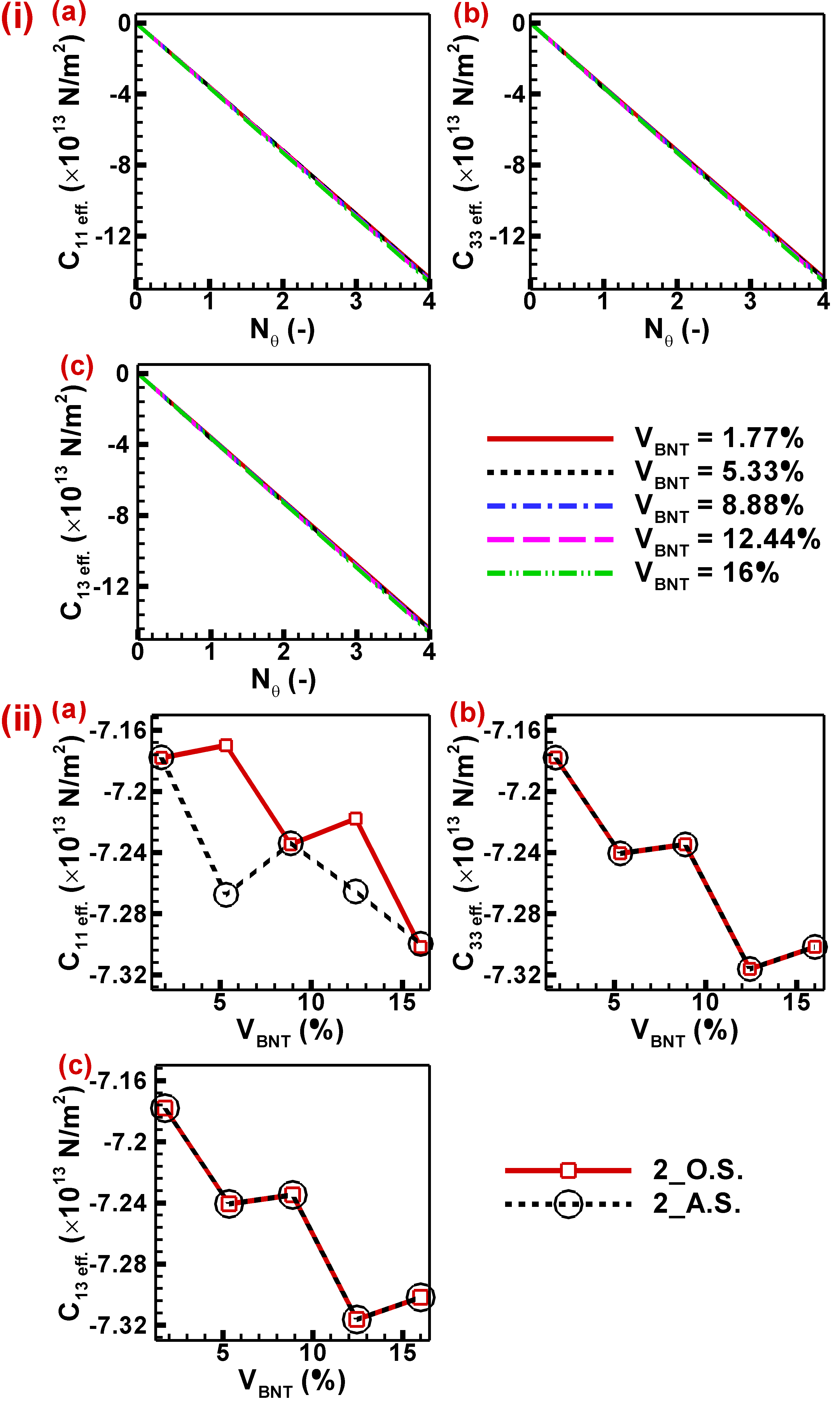
Moreover, the direction of piezoelectric inclusions assumes a significant function when the orientation of heating is altered in the context of two-sided heating. In the context of two-sided heating, two instances are often examined: neighboring wall heating and opposite-side heating. Fig. 5(i) depicts the changes in effective elastic coefficients as the thermal borders rise.
Conversely, Fig. 5(ii) specifically represents the scenario of two-side heating, where there are two thermal boundaries. The effective elastic coefficient demonstrates identical values at a volume fraction of 1.77 % for both opposite and adjacent wall heating. This is due to the uniform generation and distribution of thermal stress in a single piezoelectric inclusion. However, at a volume fraction of 5.33%, the adjacent wall heating shows higher negative values. This is because the top inclusion experiences more thermal stress compared to the bottom two inclusions. In contrast, in opposite wall heating, the temperature distribution is symmetric for all inclusions, resulting in lower negative values. At a volume percentage of 8.88%, the piezoelectric distribution demonstrates similarity in thermal boundaries. Additionally, the value of remains equal for both adjacent and opposite wall heating. Moreover, when the volume percent reaches 12.44%, the system loses its symmetry, resulting in a deviation in the observed value. However, when the volume fraction reaches 16%, the symmetry is restored, leading to the same results as before. The thermal boundary conditions in this scenario exhibit alternating symmetry and asymmetry concerning piezo-inclusion distribution in the case of two-sided heating (BC1). Hence, the effective elastic coefficients are contingent upon the alignment of piezoelectric inclusions relative to the orientation of thermal barriers. The piezoelectric inclusions exhibit symmetry about the orientation of thermal boundary conditions in the context of two-side heating, specifically in cases of adjacent and opposite wall heating, concerning and . Hence, it is evident from Fig. 5(ii(b&c)) that the coefficients demonstrate comparable values regardless of variations in the orientation of piezo-inclusions and thermal boundary conditions. This consistency arises due to the symmetrical orientation of the piezo-inclusions in accordance with thermal boundary conditions (BC2) in the given scenario.
Hence, it can be inferred that the thermal boundaries’ application and alignment have an impact on the thermo-elastic characteristics of the material. Nevertheless, this influence is not enduring and dissipates once the thermal boundary conditions are removed. The thermo-elastic and piezoelectric behaviour of a material, as well as its output responses, are influenced by the formation and degradation of thermal stress resulting from both external and internal heating. These thermal stress-induced changes have a significant impact on the effective elastic characteristics of the material.
3.1.3 Effects of temperature regulation on mechanical output parameters:
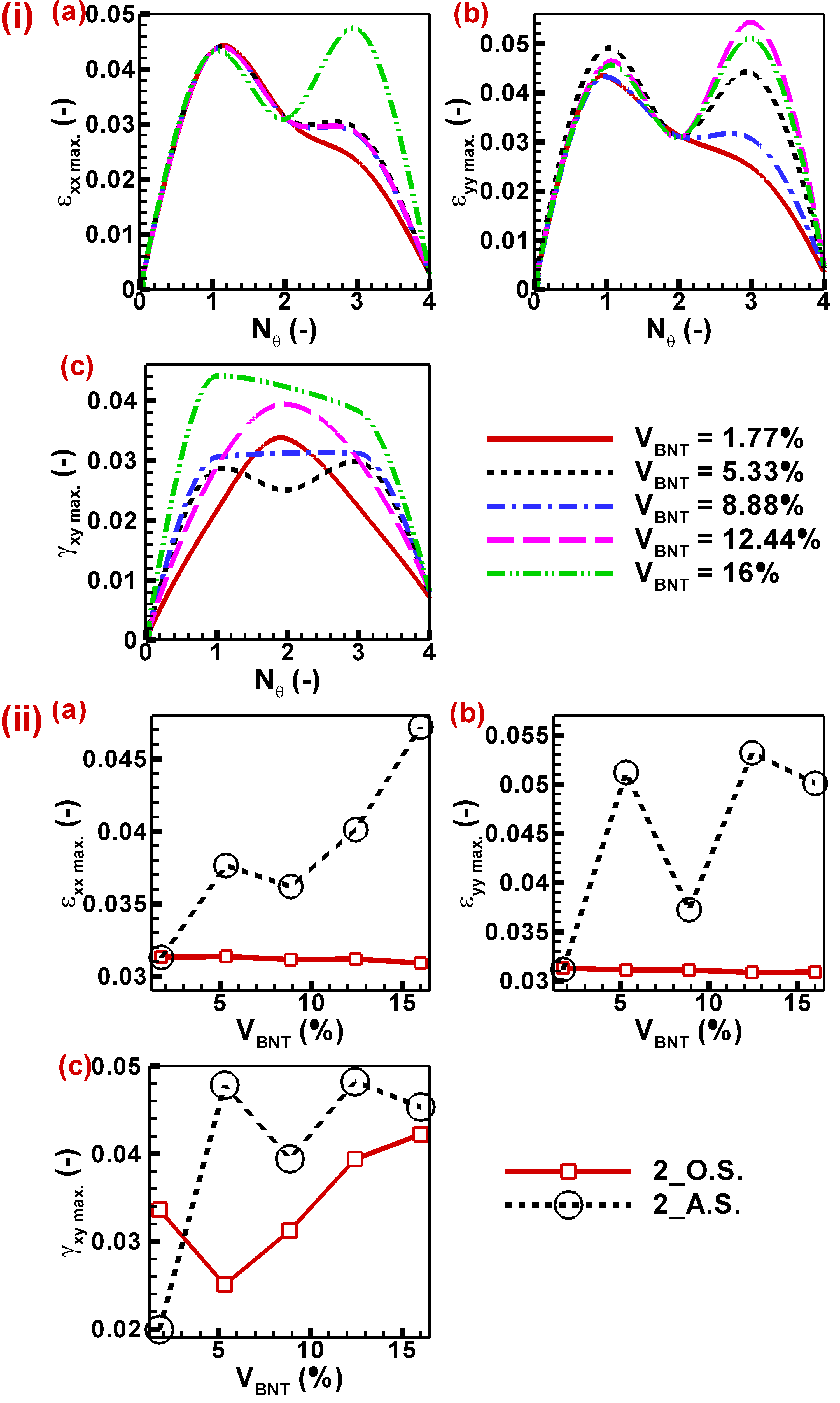
The mechanical output properties of the BNT-PDMS matrix are influenced by the application of thermal boundary conditions. This is demonstrated by the observed fluctuation in effective elastic coefficients with changes in temperature. These characteristics include principal and transverse strains. Fig. 6 (i) illustrates the temperature-dependent variations in (a) , (b) , and (c) , under the One-side heating condition. Here, represents the maximum principal strain along the x direction, represents the maximum principal strain along the y direction, and represents the maximum transverse strain. The principal strain exhibits a positive correlation with the elevation of wall temperature, primarily attributable to the emergence of thermal strain. Conversely, the thermal strain does not directly influence the transverse strain; nevertheless, there exists a fluctuation in mechanical stress resulting from the generation of thermal stress, which consequently induces variability in the transverse strain.
Moreover, the effect of one-side heating can be visualized by examining the maximum principal and transverse mechanical strains developed within the matrix. The maximum principal strains exhibit similar behaviour, but their magnitude differs due to different elastic properties in different principal directions. There is negligible change in maximum principal mechanical strains with volume fraction of piezoelectric inclusions when one side heating is absent or present at a minimal level (the magnitude of temperature difference is very small). However, it is affected by the volume fraction of BNT-type piezoelectric inclusion and its distribution as thermal strains develop and dominate near the boundary where heating is applied, as shown in Fig. 6(i(a&b)). Therefore, the maximum principal strains start to exhibit a dip at volume fraction of 5.33%, which reaches a minimum value at 8.88%, after which it starts to increase and becomes constant at 12.44% and further due to uniform or symmetric distributions of BNT-type piezo-inclusions. The amplitude of this dip rises with the temperature due to the generation of more thermal strains near the hot boundary and thermal stress where the edge is fully constrained. As mentioned above, the elastic properties are different in different principal directions. Therefore, this dip is tiny when the maximum principal strain is measured in the x direction and has a significant value in the y direction. The effect of non-uniform one-side heating on transverse strain is visualized in Fig. 6(i(c)). The variation of maximum transverse strain with volume fraction of BNT-type piezo-inclusions is negligible in the absence of thermal boundary conditions as there is variation only due to the mechanical load applied and distribution of the inclusions in the proximity of the strained boundary. The transverse strain is affected by the application of thermal coupling. However, there is no impact of thermal stress on shear stress. This variation in transverse strain is due to the free expansion nature of any material and different constraints at different geometry boundaries. This will affect the principal stresses of the body, and the transverse strain will vary accordingly as a result. The transverse strain is also dependent on the distribution of piezo-inclusions. The data demonstrates a linear growth in value until reaching a volume percentage of 8.88%. Subsequently, there is a decline in value until a volume fraction of 12.44% is reached. Following this, there is another increase in value until a volume fraction of 16% is attained. The peak’s magnitude has a positive correlation with temperature, indicating that higher temperatures result in a greater influence of thermal stress on primary stresses. The presence of these elevated amplitudes may also result in the mechanical breakdown of materials at elevated temperatures. Nevertheless, the thermoelectric effect is intensified in BNT-type piezoelectric materials as a result of elevated temperatures, leading to an increased electric field. The non-uniform temperature distribution inside the system results in a non-uniform thermoelectric effect across the geometry. This issue may be resolved by implementing a uniform heating mechanism for the matrix.
Furthermore, the impact of internal heat generation on the magnitudes of maximum principal and transverse stresses is illustrated in Fig. 6(ii). The maximum principal and transverse strains exhibit an upward trend as the amount of internal heat generation rises. This phenomenon can be attributed to the heightened thermal strain and stress that occur in the proximity of the BNT-type piezo-inclusions. Nevertheless, the connection between the mechanical parameters and the volume fraction of piezo-inclusions varies due to changes in the effective elastic property of the matrix resulting from the addition of piezo-inclusions, as well as alterations in the symmetry of their distribution. The maximum principal strain in the x direction first exhibits an upward trend until reaching a volume fraction of 5.33%. Subsequently, it experiences a decrease until a volume fraction of 8.88%. It then resumes an upward trend until reaching a volume fraction of 12.44%. However, beyond this point, it once again undergoes a decrease until a volume fraction of 16%. The observed phenomenon may be attributed to the presence of both symmetric and asymmetric distributions of piezo-inclusions concerning the mechanical boundary conditions (BC1), as the thermal boundary conditions (namely, internal heat production) for each piezo-inclusion remain uniform. The magnitude of the oscillations in the curve is positively correlated with the augmentation of internal heat generation. The magnitude of variation in heat generation is minimal until reaching a value of since the corresponding temperature difference is minor. However, at a heat generation value of , the shift becomes significant, and this effect can be further amplified with increased heat generation. The maximum principal strain in the y direction first demonstrates a decline until a volume percentage of 5.33% is reached, following which it progressively increases as the volume fraction increases. The observed phenomenon may be attributed to the presence of both symmetric and asymmetric distributions of piezo-inclusions in relation to the mechanical boundary conditions (BC2). It should be noted that the thermal boundary conditions, namely the internal heat generation, remain consistent for each BNT piezo-inclusion. The greatest transverse strain has a similar pattern to the maximum primary strain in the y direction, owing to the exact underlying cause. The influence of internal heat generation is relatively negligible at lower temperature differences but becomes significant at higher values. This results in more pronounced strains, which can enhance the piezoelectric response. However, it is essential to note that these higher strains can also cause mechanical failure in the system due to distortion of the grain boundaries.
10^{-3}
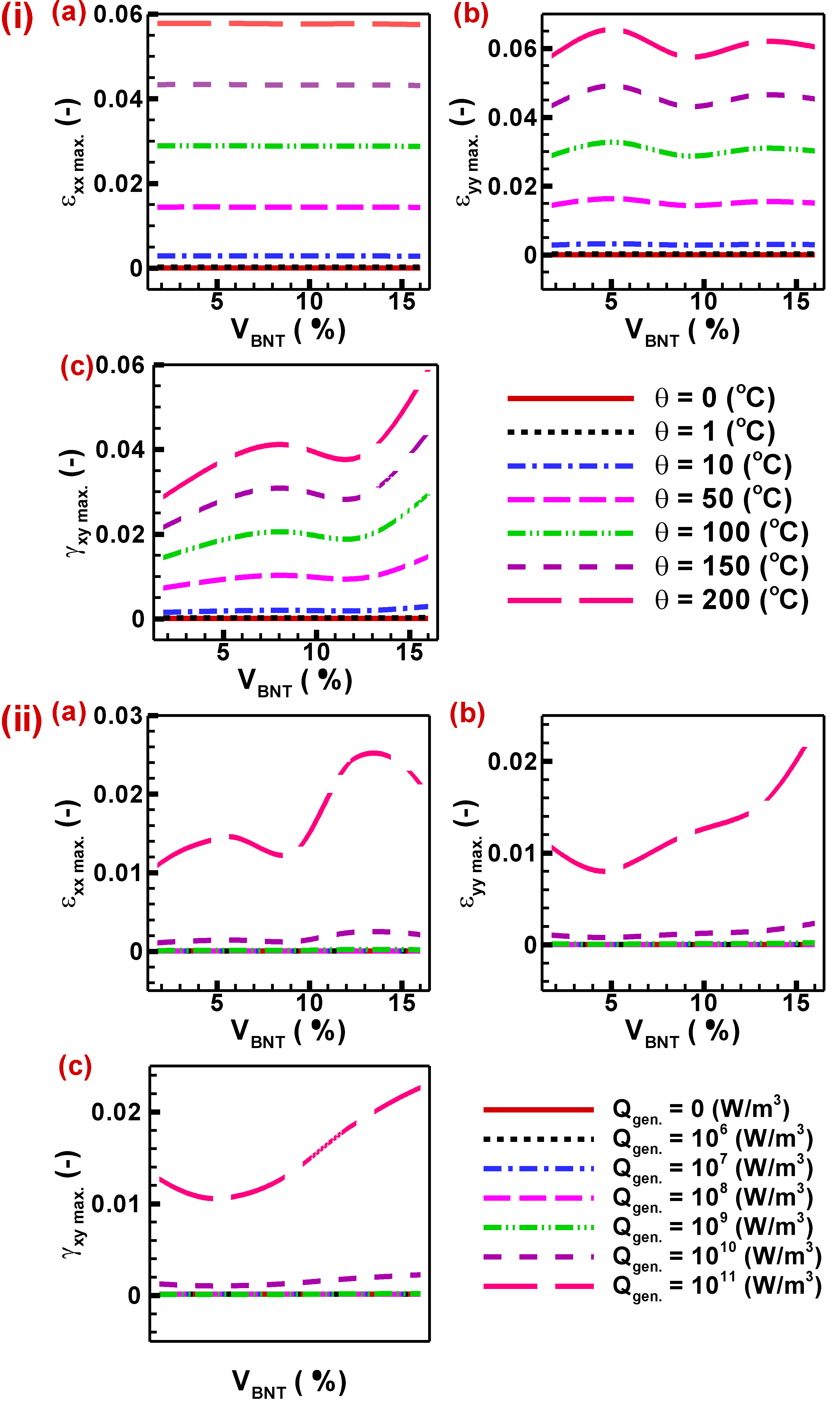
Moreover, the impact on mechanical parameters of the increase in thermal boundaries in the case of external heating of the matrix has been depicted in Fig. 7 (i). The positive maximum principal strain, which is on the order of , has a negligible magnitude and is in close proximity to zero throughout all volume fractions of BNT-type piezoelectric inclusions when there are zero thermal boundaries present. This indicates only electromechanical coupling. By introducing a single thermal boundary, specifically in the scenario of one-side heating, the maximum value of is observed to grow as a result of thermal strain. This holds true for all instances involving different volume fractions of piezoelectric inclusions. The aforementioned point represents the maximum value of for VBNT at four specific percentages: 1.77%, 5.33%, 8.88%, and 12.44%. Subsequently, the value of diminishes as a result of a decrease in temperature differential or thermal stratification. At a value of 16%, the maximum value of is achieved for three thermal barriers, as the distribution of piezoelectric inclusions normalizes thermal stratification. In contrast, the augmentation of thermal barriers to a total of four results in a heightened thermal stratification, leading to a fall in the maximum value of to lower magnitudes, approximately on the order of . The greatest primary strain in the y direction, , has a comparable behaviour to that of for values of 1.77% and 5.33%. Similarly, for values of 8.88%, 12.44%, and 16%, exhibits a similar behaviour as did for %. The observed phenomenon can be attributed to thermal stratification and piezo-inclusions’ arrangement, considering specific mechanical and thermal boundary conditions. The maximum transverse strain, denoted as , has a linear correlation with the expansion of thermal barriers, resulting in an increase in its magnitude.
When the values of are 1.77% and 12.44%, the maximum value of first increases until the number of thermal barriers approaches 2, after which it subsequently declines. The variable has a peak value at and displays a parabolic trend as a result of its symmetrical geometric characteristics. In contrast, when is equal to 8.88% and 16%, it peaks at and demonstrates a gradual decline or a near constancy in for values ranging from 1 to 3. Subsequently, it experiences a quick reduction. This phenomenon can also be attributed to the spatial arrangement of piezoelectric inclusions in accordance with the mechanical boundary conditions imposed, denoted as BC1 and BC2. The case of % also demonstrates a comparable fluctuation, however, with a little decrease in the value of maximum transverse strain at %. This may be attributed to the asymmetric distribution of piezo-inclusions in relation to the mechanical and thermal boundary conditions. There are two distinct orientations of boundaries for two-sided heating, namely neighbouring wall heating and opposite wall heating, as illustrated in Fig. 7(ii). The opposing wall heating demonstrates a consistent strain distribution inside the matrix, resulting in a nearly constant variation with volume percent BNT for maximal primary strains. The decrease in thermal strain is observed as the volume fraction increases, albeit with a minimal slope. However, it should be noted that the distribution of thermal strain is neither uniform nor symmetrical concerning the piezo-inclusions. Consequently, a zigzag pattern of maximum principal strains is obtained as the volume fraction varies in accordance with the distribution of piezo-inclusions within the matrix. The maximum transverse strain seen in neighbouring wall heating has a similar pattern to that of the maximum primary strain, which may be attributed to the same underlying reasons. However, in the case of opposite wall heating, the maximum transverse strain initially declines until a volume percentage of 5.33% is reached, after which it begins to grow with increasing volume fraction. The reason for this similarity is due to the fact that the specific situation mentioned (%) has very asymmetric piezo-inclusion distributions. The presence of an asymmetric distribution results in strain fluctuation due to disparities in the elastic and thermo-elastic characteristics of the matrix and inclusions.
Furthermore, the augmentation of thermal boundaries amplifies the strain within the system, thereby facilitating an increase in piezoelectric response. However, it is crucial to consider that such significant fluctuations in strain can also result in mechanical failures. This consideration should be taken into account when designing piezoelectric devices intended for high-temperature applications.
3.2 Effects of thermal boundary conditions on mechanical field
The influence of thermal boundary conditions on the electric field may be observed by alterations in the patterns of electric potential distribution. These changes arise from variations in the piezoelectric effect, which is induced by modifications in mechanical strain resulting from the formation of thermal strain. Furthermore, the thermoelectric effect becomes relevant when thermal boundary conditions are applied, resulting in the creation of temperature fluctuation () within the composite material. The alteration in electric potential induces changes in the distribution of electric field lines within the system, thereby modifying the effective electric displacement. Therefore, it is necessary to investigate the modification of the effective piezoelectric coefficient in both directions. Hence, this part provides a comprehensive explanation of the impact of thermal coupling on characteristics of the electric field.
3.2.1 Electric potential distribution:
The BNT-type piezoelectric-PDMS composite will behave differently depending on the temperature and mechanical boundary conditions. The heat field will modify the electrical field when thermal stresses and strains occur, affecting the piezoelectric performance of the materials. Changing the amplitude and direction of the thermal boundary affects the heat transmission rate and temperature dispersion. Changes in the number of thermal limitations will also affect the electrical field. As a result, a study into the electrical behaviour of BNT-type piezoelectric composites under different temperature boundary conditions is critical. Fig. 8 shows the contours of temperature and electric potential distributions under various boundary conditions. The heat transfer lines are drawn on the temperature distribution curve to show the direction of heat transfer and heat flow in the matrix and inclusions. When these lines enter inclusions, their slope changes considerably, becoming steeper. As a result, the heat transfer rate in the inclusions is faster than in the matrix, and the temperature gradient in the inclusions is minimized, resulting in a relatively uniform temperature within the inclusions. On the other hand, the temperature gradient in the matrix and piezo-inclusions in the direction of heat transport may be visualized. They will govern the development of thermal stresses and strains in the geometry, affecting the BNT material’s piezoelectric response. The electric field lines are overlaid on the electric potential distribution to determine the intensity distribution of the electric field in the matrix.
Until there is no external or internal heating of the geometry, the electric potential distribution, as illustrated in Fig. 8(i), solely relies on mechanical stress. The electrical potential distribution and electric field intensity are uniform along the BNT inclusions. Thermal strain induction increased strain owing to thermal boundary conditions, which will help strengthen the thermoelectric effect over piezoelectric inclusions. The geometry is heated on one side in Fig. 8(ii), and a thermal boundary condition is imposed on the exact boundary where mechanical loading is applied. In contrast, all other borders stay at room temperature. Since the thermoelectric effect prevails near the hot wall and lessens towards the cold wall, the total piezoelectric response improves as inclusions near the hot wall display more robust thermoelectric behaviour. Increasing the thermal boundary further enhances the electric distribution. The mechanically laden fence and the neighbouring wall are heated, while the other remains at room temperature (see Fig. 8(iii)). As the high-temperature zone expands, so does the amount and dispersion of electric potential.
Due to the thermoelectric effect, maximum electric potential is found at the boundary where heat is delivered, but only piezoelectric response is recorded near the cool wall area. The strength of electric field lines can be seen at the hot and cold wall regions, indicating that intensity is higher near the hot wall due to improved thermoelectric response and lower near the hard border due to lower thermoelectric impact. In addition, the BNT-type piezoelectric composite is explored for two opposing wall heating sides that exhibit a unique electric potential distribution pattern, as shown in Fig. 8 (iv). Thermal boundary conditions are applied to both the mechanical loading and constraint boundaries while the other walls remain at ambient temperature. The electric distribution follows the temperature distribution inside the geometry. The heat transfer direction is from hot to cold walls, and heat transmission at the geometry’s centre is zero.
Similarly, the electric distribution is most extensive at both hot walls. It diminishes as we move away from the walls due to electric potential distribution, while inclusions at cool walls and the centre of geometry display reduced thermoelectric impact. However, with this type of thermal loading, the electric potential distribution for all BNT piezo-inclusions is virtually uniform, as are the electric field lines, which may benefit a consistent piezoelectric response.
Increasing the number of thermal boundaries to three expands the thermoelectric effect distribution even more, as seen in Fig. 8(v). In this situation, all three walls are heated except for the mechanical constraint boundary, and heat is transmitted from these three walls to the mechanical constraint border. The inclusions near the cold walls have less thermoelectric effect, but the overall piezoelectric distribution improves. Furthermore, in Fig. 8(vi), the number of thermal boundaries is increased to four, and it is revealed that no temperature gradient is observed inside the geometry, even though the temperature of the entire geometry rises due to heating. A consistent yet enhanced electric potential distribution was observed over the whole geometry. The thermoelectric effect induced by all side heating causes the increase in electric potential. The uniform electric potential distribution indicates that the strength of the electric field generated by temperature rise is constant in all directions. The whole shape is intended to have a consistent and enhanced piezoelectric response throughout all inclusions, albeit this may vary due to mechanical loading.
We previously investigated the effect of non-uniform and uniform external heating on the BNT-type piezoelectric composite. We found that an increase in thermal barriers increases the spread of thermoelectric effect distribution inside the geometry, which becomes uniform in the case of constant heating. This is thought to improve piezoelectric performance; however, the emphasis on internal heat production in the electrical field has yet to be well investigated, as shown in Fig. 8(vii). All boundaries are kept at ambient temperature, and each piezoelectric inclusion generates heat inside. The heat transmission from the source to the walls is uniform, and the temperature distribution is the same, higher in the centre and decreasing uniformly towards the wall; nevertheless, heat generation from each inclusion enhances the temperature at that precise location. Electric potential distribution is also the same, with a maximum in the centre inclusion and a reduction as we travel towards the walls. Although the electric potential is enhanced at each inclusion owing to heating and the created thermal effect, the influence is less than in the central inclusion. The most important characteristic is that all inclusions have a more significant thermoelectric impact, which is predicted to improve piezoelectric performance.
External or internal heating may positively influence the electric field and increase the electric potential and intensity, resulting in a better piezoelectric response. On the other hand, uniformly heated surfaces offer a uniformly enhanced electrical field, which is more beneficial for improving homogeneous piezoelectric response.
3.2.2 Effects of thermal boundary conditions on effective piezoelectric coefficients of materials:
The piezoelectric coefficients exhibit a linear relationship with temperature difference, as seen in Fig. 9(i) for the case of one-sided heating. Increasing the volume percentage of BNT inclusions leads to a further enhancement in the piezoelectric response. Given the aforementioned circumstances, thermo-electromechanical coupling has an impact on the performance of piezoelectric materials. The performance of piezoelectric materials is influenced by temperature due to the presence of thermoelectric coupling, which becomes more pronounced as the temperature rises, hence enhancing the piezoelectric performance. The piezoelectric coefficient is enhanced when the temperature increases due to the heightened thermal strain. This leads to an increase in the overall strain, so generating a more resilient piezoelectric response inside the inclusions. The application of mechanical strain in the x-direction induces a piezoelectric response, namely the generation of , in the z-direction. Despite the absence of symmetry in the geometry of piezoelectric inclusions, both the effective and exhibit similar rates of growth in magnitude. This phenomenon can be attributed to the uniform dispersion of thermal stress in all orientations. Due to the diverse piezoelectric properties and thermoelectric potential distribution in different orientations, the magnitude of is marginally greater than that of . Moreover, the piezoelectric coefficients exhibit an increase in effectiveness as temperature rises, mostly attributed to the assistance provided by thermoelectric coupling. This phenomenon becomes more pronounced at elevated temperatures and when a larger proportion of the material consists of piezoelectric inclusions. Nonetheless, it is crucial to consider the influence of phase shift and ferroelectric domain switching on the amplification of the piezoelectric response in order to accurately assess the true impact and calculate the threshold value for temperature augmentation.
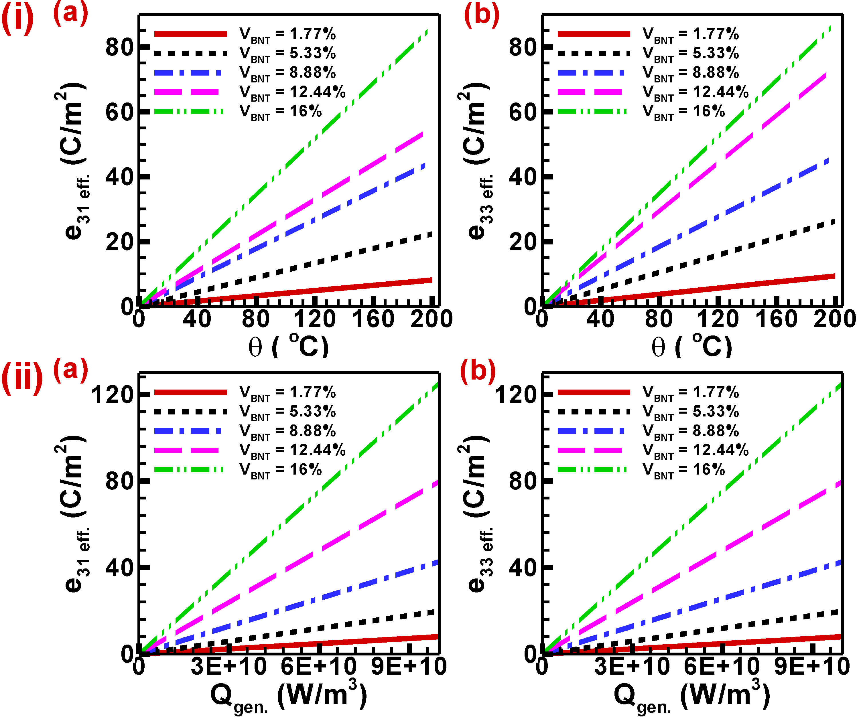
Fig. 9(ii) illustrates the linear relationship between the piezoelectric coefficients and internal heat generation. An augmentation in the piezoelectric response can be achieved by increasing the volume percentage of BNT inclusions. This observation implies that the performance of piezoelectric materials is influenced by thermo-electromechanical coupling. The thermoelectric effects, which contribute to the enhancement of piezoelectric performance, have a more substantial influence as the amount of internal heat generation grows. This leads to non-uniform temperature distributions inside the geometry and subsequently affects the performance of the piezoelectric material. The enhancement of the piezoelectric coefficient in the inclusions may be attributed to the escalation of thermal strain resulting from an increase in internal heat generation. This heightened thermal strain leads to an overall increase in strain, so generating a more resilient piezoelectric response. The mechanical strain applied in the x-direction generates the piezoelectric response (a) in the z-direction. Even though the geometry lacks symmetry of piezoelectric inclusions, the effective , and . display identical magnitude increase rates. This is owing to the similar distribution of temperature leading to symmetric thermal stress in all directions. Because the material only has varied piezoelectric capabilities in various directions and the thermoelectric potential distribution is uniform, the magnitude of is somewhat larger than (a) . Furthermore, the effective piezoelectric coefficients rise with internal heat generation due to thermoelectric assistance through thermoelectric coupling, which becomes more dominant at higher values of internal heat generation and a more significant volume percentage of piezoelectric inclusions. However, the amplification of piezoelectric response is also sensitive to phase shift and ferroelectric domain switching, which must be addressed to determine the actual impact and internal heat generation threshold value.
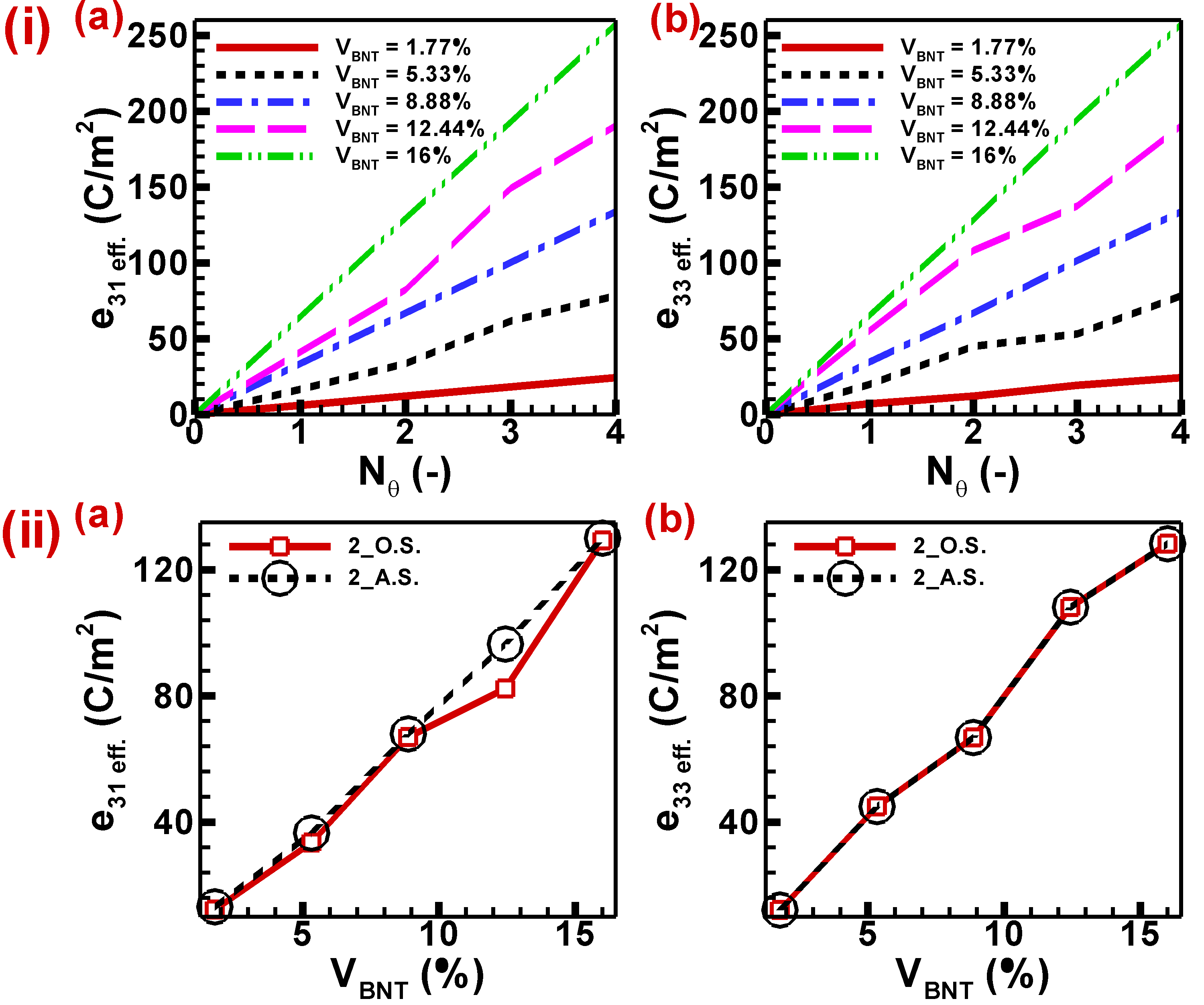
Moreover, Fig. 10(i) illustrates the influence of increased thermal boundaries on the effective piezoelectric coefficients, which exhibit a positive correlation with the augmentation of thermal boundaries. The effective elastic constants , and display a linear relationship with the number of thermal barriers, characterized by a consistent slope for volume fractions of 1.77%, 8.88%, and 16%, correspondingly. The piezoelectric coefficients exhibit a change in slope as the temperature limits increase, with volume fractions of BNT at 5.33% and 12.44%. This shift is attributed to the asymmetric distribution of piezo-inclusions. The disparity between the effective piezoelectric coefficients , and is minimal due to the slight variations in the piezoelectric characteristics of BNT in various directions. The piezoelectric coefficient demonstrates enhanced effectiveness when the thermal boundaries are expanded, resulting in an amplified thermoelectric effect caused by an escalation in temperature disparity. Consequently, the thermoelectric effect is amplified by the increasing volume percentage of BNT. Moreover, there are two distinct orientations for two-sided heating, namely neighbouring wall heating and opposite wall heating. The two distinct orientations of dual-side heating have varying impacts on the effective piezoelectric coefficients. The variation of the effective permittivity is influenced by the divergence in mechanical and thermal boundary conditions relative to the poling direction of the piezoelectric material. The value of remains consistent for both adjacent and opposite wall heating scenarios due to the symmetric nature of the piezo-inclusion distribution under certain mechanical and thermal boundary conditions. This holds true for values of 1.77%, 8.88%, and 16%. The values, namely 5.33% and 12.44%, exhibit modest variations across the two orientations of two-side heating. This discrepancy can be attributed to the asymmetric distribution of piezo-inclusions. The heating of the opposite wall exhibits significantly lower values compared to the heating of neighbouring walls, which can be attributed to a more equal distribution of thermal strain. Furthermore, the value of the effective dielectric constant , remains same for both adjacent and opposite wall heating scenarios since the poling direction aligns with the mechanical and thermal boundary conditions as shown in Fig. 10(ii). The thermoelectric effect seen across each piezo-inclusion remains consistent under both temperature conditions of two-side heating, specifically in relation to the effective piezoelectric coefficient. The thermo-mechanical coupling phenomenon leads to an enhancement of the effective piezoelectric coefficients. Nevertheless, it is crucial to consider the potential occurrence of mechanical failure resulting from grain boundary distraction caused by excessive thermal stress.
3.2.3 Effects of thermal boundary regulation on electrical output parameters:
The variation of piezoelectric and elastic coefficients with temperature indicates that the application of thermal boundary conditions influences the electrical output qualities of the BNT-PDMS matrix. The effective material characteristics are influenced by the thermal boundary condition, and the addition of piezoelectric inclusions to the original matrix further impacts these properties. Consequently, the influence of heat coupling on electromechanical behaviour is not the only factor at play; an elevation in the volume percentage of BNT inclusions also has an effect. Furthermore, the performance evaluation of the BNT-PDMS composite may be conducted by analyzing several output metrics, such as electric field intensity and potential, in addition to considering its effective material features.
Furthermore, the impact of unilateral heating on the electric output characteristics may be seen by examining the variation of the maximum electric potential with the volume % of BNT-type piezoelectric inclusions at various operating temperatures, as depicted in Fig. 11(i(a)). The increase in the volume percentage of piezo-inclusions leads to an increase in the maximum potential generated in the piezoelectric matrix without considering thermal coupling. However, the observed increase is negligible since the electric potential is dispersed in accordance with the doping material’s geometry when piezoelectric material is introduced. The electric potential is exclusively influenced by the mechanical input that is applied. The application of a temperature boundary condition on one side of the geometry results in the uniform generation of the thermoelectric effect throughout all areas as the temperature increases. Consequently, this leads to an increase in the maximum electric potential. The amount of this increment has a negative correlation with lower temperatures and a positive correlation with higher temperatures. Nevertheless, the impact of volume fraction on maximum electric potential is influenced by one-sided heating. In contrast to the relatively moderate piezoelectric effects, the presence of piezo-inclusions inside the region exhibits a more pronounced thermoelectric influence. The variation of Vmax is also contingent upon the distribution of piezo-inclusions. Initially, shows an upward trend as the volume fraction grows, peaking at a volume fraction of 8.88%. Subsequently, begins to decline, reaching a global minimum at a volume fraction of 12.44%. However, it subsequently climbs once again, reaching a maximum value at a volume fraction of 16%. The magnitude of at a volume percent is significantly greater than 1.77%. Additionally, the thermo-electromechanical coupling demonstrates substantial values of around 80V at a volume fraction of 16%, whereas it is on the order of V when simply considering electromechanical coupling. In the context of thermo-electromechanical coupling, it is observed that the value of exhibits numerous rises in comparison to electromechanical coupling.

Figure 11(i(b)) illustrates the relationship between the maximum electric field intensity and the volume percent of BNT inclusions at various operating temperatures. The logarithmic scale is utilized to facilitate the representation and understanding of the maximum electric field intensity. The incorporation of BNT inclusions has resulted in an augmentation of the value. Irrespective of the temperature boundary conditions, it can be observed that the maximum electric field strength exhibits a linear growth pattern in relation to the volume % of piezo-inclusions. When the temperature boundary condition is imposed on a single side of the matrix, the magnitude of this fluctuation increases with the introduction of one-sided heating. Within the region of elevated temperature, the thermoelectric phenomenon surpasses the piezoelectric phenomenon, resulting in an amplified enhancement amplitude when piezo-inclusions are present. This overall increase in amplitude may be attributed to the rise in temperature. The thermoelectric effect is influenced by the distribution of inclusions inside the matrix due to the inconsistent temperature distribution across the geometry. Consequently, the observed phenomenon manifests itself in the form of variations in the intensity of the electric field. The logarithmic value of the electric field ( ) at is approximately three times compared to the case when heating is absent, which indicates that Emax. in thermo-electromechanical coupling (presence of different thermal boundary conditions) is about 1000 times of in electromechanical coupling (absence of thermal boundary conditions) of BNT-type piezoelectric composites.
Further, Fig. 11(ii) exhibits the variation of and with volume fraction at different values of internal heat generation. The quantities first exhibit a decline until reaching a volume fraction of 5.33%. Subsequently, they begin to climb and continue to do so as the volume percentage further increases. Furthermore, it should be noted that the Vmax exhibits a rise as the internal heat production grows. However, it is important to acknowledge that this variation is rather little when considering the modest temperature difference up to an internal heat generation of . Conversely, at an internal heat generation of , the value of becomes significantly larger owing to the presence of larger theta values. Nevertheless, the logarithmic representation of the maximum electric field intensity () demonstrates a consistent increase in the presence of internal heat generation. This uniform increment is due to the logarithmic scale employed. If were represented on an absolute scale, the variance would not be uniform and would likely be far larger. The voltage and electric field output of each piezoelectric inclusion would exhibit a notable increase when subjected to increasing levels of internal heat production, owing to the thermoelectric effect present at each piezo-inclusion.
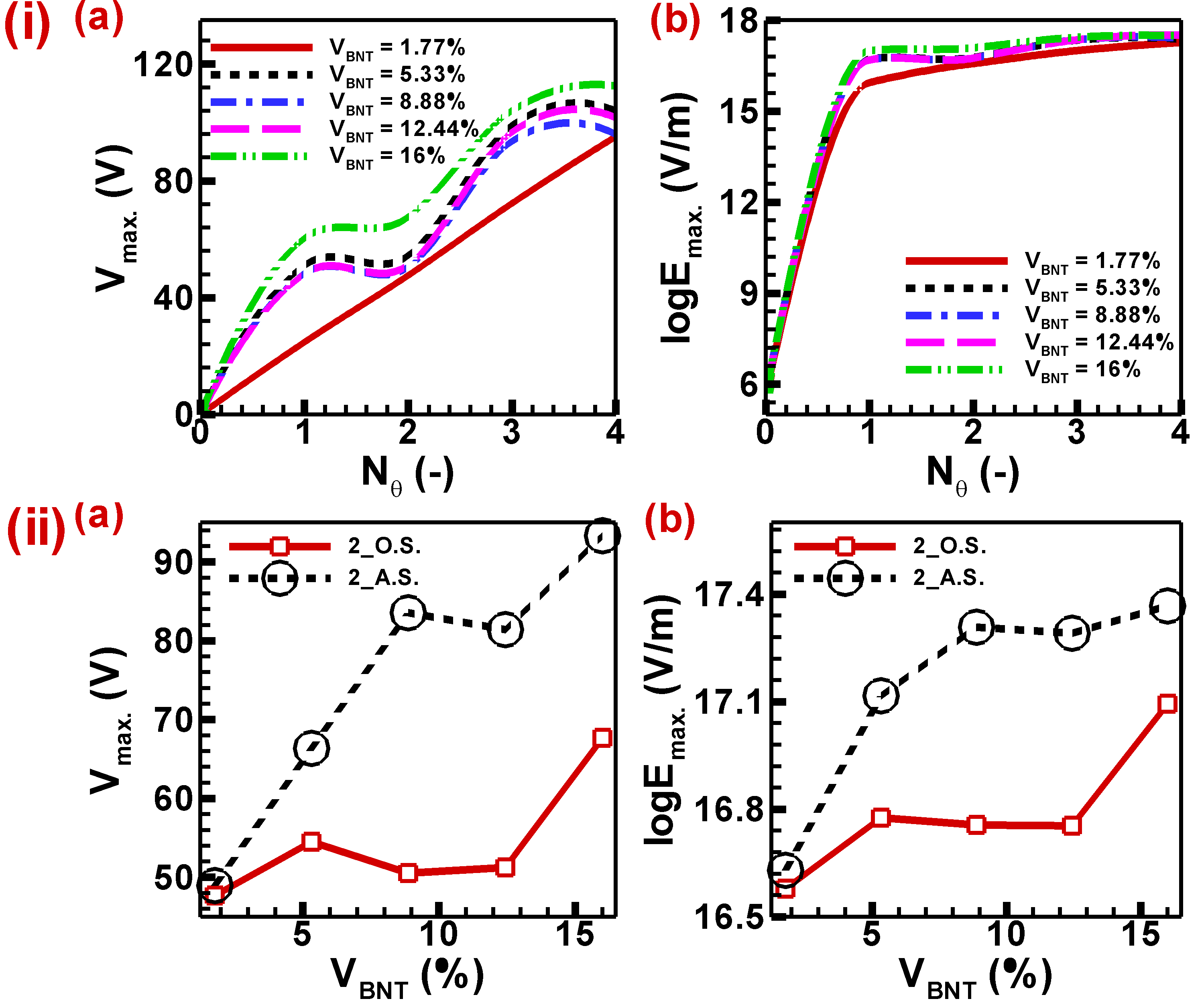
Moreover, Fig. 12(i) exhibits the variation of electric parameters such as and with number of thermal boundaries. The maximum electric potential first exhibits an upward trend as grows until reaches 1. Subsequently, Vmax remains constant from to 2 and then resumes its upward trajectory. In contrast, the logarithm has a linear relationship with until 1, characterized by a steeper slope. Subsequently, the logarithm experiences a growth with a diminished slope or rate. The observed phenomenon can be attributed to the relationship between thermal boundaries and thermal stratification. As the thermal boundaries increase, the thermal stratification also increases. Consequently, the growth of electric field intensity experiences a reduced slope. However, it is worth noting that the electric field intensity exhibits a significantly higher value when subjected to all-side heating boundary conditions in comparison to other external and internal heating conditions. Moreover, there exist two distinct orientations of two-sided heating boundary conditions, namely neighbouring wall heating and opposite wall heating. The heating of the neighbouring wall demonstrates a non-uniform distribution of temperature differences within the geometry. This non-uniformity leads to the formation of a thermoelectric effect, resulting in larger values of and compared to the opposite wall heating, as seen in Figure 12(ii). The observed variation in quantities related to adjacent and opposite wall heating can be attributed to the asymmetric distribution of piezo-inclusions along the direction of applied boundary conditions. This asymmetry is also responsible for the zigzag pattern of increment in these quantities with respect to the volume fraction at these two thermal boundary conditions.
The phenomena of thermo-mechanical coupling results in an augmentation of electric output characteristics for BNT-type composites. However, it is essential to take into account the possible manifestation of mechanical failure due to grain boundary distortion induced by extreme thermal stress.
3.3 Effects of flexoelectricity on mechanical and electric output parameters accounting for thermo-electromechanical coupling:
Flexoelectricity is a characteristic of dielectric materials with an inherent electrical polarization that arises from a gradient in strain. Flexoelectricity is a phenomenon that exhibits a close association with piezoelectricity. However, it is essential to note that piezoelectricity pertains to the polarization resulting from a uniform strain, whereas flexoelectricity particularly pertains to the polarization arising from strain variations across different points inside the material. Flexoelectricity is a non-local size-dependent effect. In the context of this investigation, the impact of flexoelectricity is considered insignificant due to the relatively larger size of the piezo-inclusions in comparison to the scale of flexoelectric coefficients associated with the BNT materials.
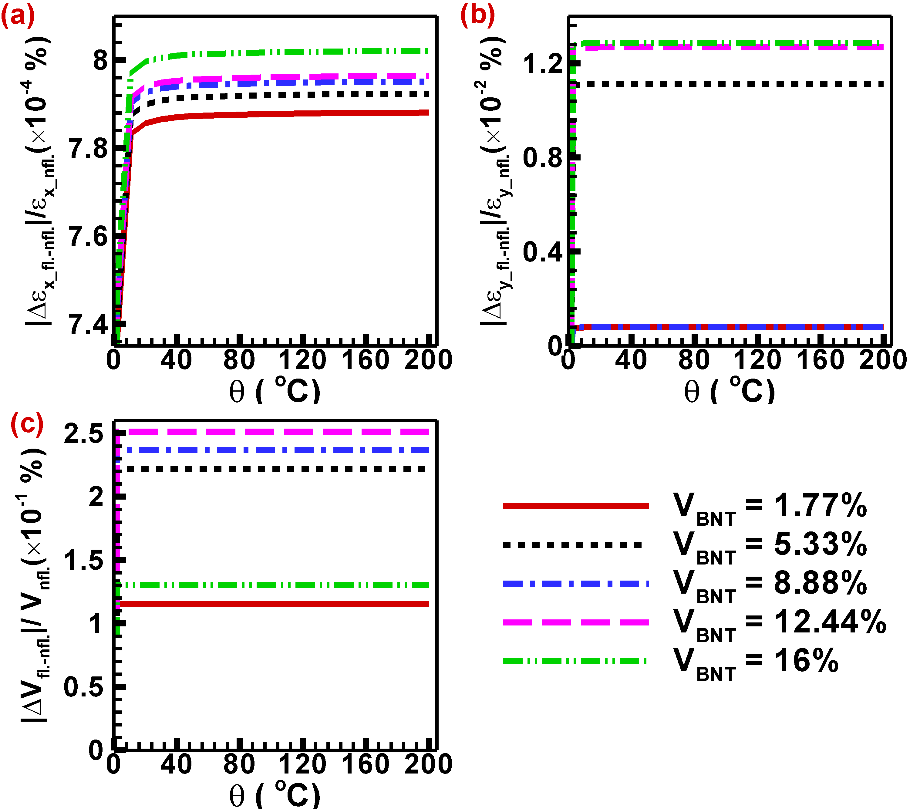
Figure 13 illustrates the relationship between temperature and the mechanical and electrical output parameters, namely principal strains and output voltage, for different volume fractions of BNT inclusions. This depiction aims to examine the behaviour of BNT material when subjected to flexoelectricity in the context of thermo-electromechanical coupling. The research has revealed that the magnitude of major strain in the x direction is around %, while in the y direction it is approximately %. These values may be considered inconsequential. Therefore, it can be concluded that the impact of flexoelectricity on the mechanical domain is insignificant when considering piezo-inclusions of this particular size. Moreover, the effect of flexoelectricity on electric field parameters, such as electric potential, is around %, signifying a relatively little influence, yet greater than that of the mechanical field. Based on the findings of this study, it can be inferred that the impact of flexoelectricity is insignificant for the given dimensions of the piezo-inclusions. Also, there is no effect on increasing temperature difference has been observed at flexoelectricity for this scale of piezo-inclusions. However, a potential increase in the flexoelectric impact may be seen by reducing the size of the piezo-inclusions. It is important to acknowledge that investigating this aspect falls outside the scope of the present research.
4 Conclusions
A two-dimensional computational framework has been established to examine the impact of thermo-electromechanical coupling on the performance of lead-free BNT material when subjected to high-temperature haptic applications. The thermo-electromechanical modelling of BNT ceramics explicitly examines the macroscopic effects of phase changes on mechanical and electric field parameters. The thermal stability of such material must be evaluated due to its complex phase and domain structures, which entirely depend on the material’s temperature and grow even more complicated at higher temperatures. The effective elastic and piezoelectric properties and the mechanical and electric field parameters of the two-dimensional framework have been investigated under various temperature and mechanical boundary conditions. Based on the outcomes of the study, several inferences can be drawn.
-
•
The effective elastic coefficients exhibit higher negative values for thermo-electromechanical coupling due to the generation of thermal stress.
-
•
The effect of the volume fraction of BNT inclusions on effective elastic coefficients in the principal plane is compensated by thermal stress for all thermal boundary conditions irrespective of mechanical boundary conditions.
-
•
The considerable thermal strain is beneficial for a higher piezoelectric response. However, there must be a limit as it can cause material to fail mechanically due to grain boundary distortion.
-
•
The electric field output parameters and effective piezoelectric coefficient are enhanced due to the thermoelectric and piezoelectric effects.
-
•
Among all thermal boundary conditions, uniform all-side heating (number of thermal boundaries 4) exhibits the highest thermoelectric effect. Electric field output values like electric potential and intensity show enormous increments compared to electromechanical coupling.
It is observed that compared to purely electromechanical case, BNT-type piezoelectric composites behave differently when thermal field is accounted consistently in the modelling main characteristics of these lead-free materials. Therefore, the effect of thermo-electromechanical coupling can’t be neglected when designing lead-free BNT- type piezoelectric materials for devices with thermal management requirements, e.g., such as those used in haptic applications. The effects of phase change and micro-domain dynamics have not been considered in this study, where the main focus was to understand the effect of temperature on the overall performance of BNT-based lead-free piezoelectric composites based on the fully coupled thermo-electromechanical model.
References
- [1] Jueyu Chen, Edwin Hang Tong Teo, and Kui Yao. Electromechanical actuators for haptic feedback with fingertip contact. Actuators, 12, 2023.
- [2] Van Cuong Nguyen, Victor Oliva-Torres, Sophie Bernadet, Guilhem Rival, Claude Richard, Jean Fabien Capsal, Pierre Jean Cottinet, and Minh Quyen Le. Haptic feedback device using 3d-printed flexible, multilayered piezoelectric coating for in-car touchscreen interface. Micromachines, 14:1–31, 2023.
- [3] Claudia Krogmeier, Christos Mousas, and David Whittinghill. Human-virtual character interaction: Toward understanding the influence of haptic feedback. Computer Animation and Virtual Worlds, 30:e1883, 5 2019.
- [4] Jagdish A. Krishnaswamy, Luis Rodriguez-Tembleque, Roderick Melnik, Federico C. Buroni, and Andres Saez. Size dependent electro-elastic enhancement in geometrically anisotropic lead-free piezocomposites. International Journal of Mechanical Sciences, 182, 2020.
- [5] Jagdish A. Krishnaswamy, Federico C. Buroni, Enrique Garciá-Maciás, Roderick Melnik, Luis Rodriguez-Tembleque, and Andres Saez. Design of lead-free pvdf/cnt/batio3 piezocomposites for sensing and energy harvesting: The role of polycrystallinity, nanoadditives, and anisotropy. Smart Materials and Structures, 29, 2020.
- [6] T Ibn-Mohammed, S C L Koh, I M Reaney, D C Sinclair, K B Mustapha, A Acquaye, and D Wang. Are lead-free piezoelectrics more environmentally friendly? MRS Communications, 7:1–7, 2017.
- [7] P K Panda. Review: environmental friendly lead-free piezoelectric materials. Journal of Materials Science, 44:5049–5062, 2009.
- [8] Samuel Collin, Amritha Baskar, Deepthi Mariam Geevarghese, Mohamed Niyaz Vellala Syed Ali, Praveena Bahubali, Rajan Choudhary, Vladislav Lvov, Gabriel Ibrahin Tovar, Fedor Senatov, Sivasankar Koppala, and Sasikumar Swamiappan. Bioaccumulation of lead (pb) and its effects in plants: A review. Journal of Hazardous Materials Letters, 3:100064, 2022.
- [9] Yugong Wu, Huili Zhang, Yue Zhang, Jinyi Ma, and Daohua Xie. Lead-free piezoelectric ceramics with composition of (0.97-x)na 1/2 bi 1/2 tio 3 -0.03nanbo 3 - x batio 3. Journal of Materials Science - J MATER SCI, 38:987–994, 03 2003.
- [10] Deepam Maurya, Mahesh Peddigari, Min-Gyu Kang, Liwei Geng, Nathan Sharpes, Annapureddy Venkateswarlu, Haribabu Palneedi, Rammohan Sriramdas, Yongke Yan, Hyun-Cheol Song, Yu Wang, Jungho Ryu, and s.Jeba Priya. Lead-free piezoelectric materials and composites for high power density energy harvesting. Journal of Materials Research, 33:1–29, 6 2018.
- [11] Benjamin Tiller, Andrew Reid, Botong Zhu, Jose Guerreiro, Roger Domingo-Roca, Joseph Jackson, and James Windmill. Piezoelectric microphone via a digital light processing 3d printing process. Materials and Design, 165:107593, 3 2019.
- [12] Tadashi Takenaka and Hajime Nagata. Current status and prospects of lead-free piezoelectric ceramics. Journal of the European Ceramic Society, 25(12):2693–2700, 2005. Elecroceramics IX.
- [13] Sung-Ho Shin, Young-Hwan Kim, Min Hyung Lee, Joo-Yun Jung, and Junghyo Nah. Hemispherically aggregated batio3 nanoparticle composite thin film for high-performance flexible piezoelectric nanogenerator. ACS nano, 8:2766–2773, 3 2014.
- [14] Yi Quan, Lingyan Wang, Wei Ren, Jinyan Zhao, Jian Zhuang, Kun Zheng, Zhe Wang, Tomoaki Karaki, Zhishui Jiang, and Li Wen. Enhanced electrical properties of lead-free piezoelectric knln-bz-bnt ceramics with the modification of sm3+ ions. Frontiers in Materials, 8:1–5, 2021.
- [15] Yu Zhang, Yezhan Lin, Ruofan Li, Zhengran Chen, Di Zeng, Shuai Chen, Wenjing Wang, Ling Zhang, Wenzhong Wang, Hengchang Nie, and Genshui Wang. Enhanced piezo-catalytic h2o2 production over bi0.5na0.5tio3 via piezoelectricity enhancement and surface engineering. Chemical Engineering Journal, 465:143043, 2023.
- [16] Dragan Damjanovic. Ferroelectric, dielectric and piezoelectric properties of ferroelectric thin films and ceramics. Reports on Progress in Physics, 61:1267, 1998.
- [17] Qing Liu, Yichi Zhang, Jing Gao, Zhou Zhen, Dong Yang, Kai-Yang Lee, Andrew Studer, Manuel Hinterstein, Ke Wang, Xiaowen Zhang, Longtu Li, and Jing-Feng Li. Practical high-performance lead-free piezoelectrics: structural flexibility beyond utilizing multiphase coexistence. 7:355–365, 11 2019.
- [18] Hua Wang, Huan Yuan, Qiang Hu, Keying Wu, Qiaoji Zheng, and Dunmin Lin. Exploring the high-performance (1-x)batio3-xcazro3 piezoceramics with multiphase coexistence (r-o-t) from internal lattice distortion and domain features. Journal of Alloys and Compounds, 853:157167, 2021.
- [19] Wangfeng Bai, Leijie Wang, Peng Zheng, Fei Wen, Jiwei Zhai, and Zhenguo Ji. Pairing high piezoelectric properties and enhanced thermal stability in grain-oriented bnt-based lead-free piezoceramics. Ceramics International, 44:11402–11409, 2018.
- [20] Jigong Hao, Wei Li, Jiwei Zhai, and Haydn Chen. Progress in high-strain perovskite piezoelectric ceramics. Materials Science and Engineering: R: Reports, 135:1–57, 2019.
- [21] Badari Narayana Rao, Andy N Fitch, and Rajeev Ranjan. Ferroelectric-ferroelectric phase coexistence in na 1/2 bi 1/2 tio 3. Physical Review B, 87:060102, 2013.
- [22] S Gorfman and Pam A Thomas. Evidence for a non-rhombohedral average structure in the lead-free piezoelectric material na0. 5bi0. 5tio3. Journal of Applied Crystallography, 43:1409–1414, 2010.
- [23] Vincent Dorcet, Gilles Trolliard, and PJCoM Boullay. Reinvestigation of phase transitions in na0. 5bi0. 5tio3 by tem. part i: First order rhombohedral to orthorhombic phase transition. Chemistry of Materials, 20:5061–5073, 2008.
- [24] Vincent Dorcet and Gilles Trolliard. A transmission electron microscopy study of the a-site disordered perovskite na0. 5bi0. 5tio3. Acta Materialia, 56:1753–1761, 2008.
- [25] Vincent Dorcet, Gilles Trolliard, and P Boullay. The structural origin of the antiferroelectric properties and relaxor behavior of na0. 5bi0. 5tio3. Journal of magnetism and magnetic materials, 321:1758–1761, 2009.
- [26] Gilles Trolliard and Vincent Dorcet. Reinvestigation of phase transitions in na0. 5bi0. 5tio3 by tem. part ii: Second order orthorhombic to tetragonal phase transition. Chemistry of materials, 20:5074–5082, 2008.
- [27] M Geday, J Kreisel, A M Glazer, and K Roleder. Birefringence imaging of phase transitions: application to na0.5bi0.5tio3. Journal of Applied Crystallography, 33:909–914, 6 2000.
- [28] Jie Yin, Yangming Wang, Yuxing Zhang, Bo Wu, and Jiagang Wu. Thermal depolarization regulation by oxides selection in lead-free bnt/oxides piezoelectric composites. Acta Materialia, 158:269–277, 2018.
- [29] Yantao Liu, Wei Ren, Jinyan Zhao, Lingyan Wang, Peng Shi, and Zuo Guang Ye. Effect of sintering temperature on structural and electrical properties of lead-free bnt-bt piezoelectric thick films. Ceramics International, 41:S259–S264, 2015.
- [30] Linghao Hou, Changrong Zhou, Qingning Li, Rui Li, Changlai Yuan, Jiwen Xu, and Guanghui Rao. Giant strain with ultra-low hysteresis by tailoring relaxor temperature and pnrs dynamic in bnt-based lead-free piezoelectric ceramics. Ceramics International, 48:13125–13133, 2022.
- [31] Srinivas Pattipaka, A. R. James, and Pamu Dobbidi. Enhanced dielectric and piezoelectric properties of bnt-knng piezoelectric ceramics. Journal of Alloys and Compounds, 765:1195–1208, 2018.
- [32] Parkpoom Jarupoom and Pharatree Jaita. Enhanced electrical and energy harvesting performances of lead-free bmt modified bnt piezoelectric ceramics. Journal of Asian Ceramic Societies, 10:498–513, 2022.
- [33] R. I. Mahdi and W. H. Abd Majid. Piezoelectric and pyroelectric properties of bnt-base ternary lead-free ceramic-polymer nanocomposites under different poling conditions. RSC Advances, 6:81296–81309, 2016.
- [34] Yule Yang, Juanjuan Wang, Ruiyi Jing, Wenjing Shi, Leiyang Zhang, Chao Li, Xinyu Zeng, Fukang Chen, Gang Liu, Xiaolian Chao, Yan Yan, and Li Jin. Achieving high dielectric energy-storage properties through a phase coexistence design and viscous polymer process in bnt-based ceramics. Journal of Materiomics, 2023.
- [35] Ali Hussain, Chang Won Ahn, Jae Shin Lee, Aman Ullah, and Ill Won Kim. Large electric-field-induced strain in zr-modified lead-free bi0.5(na0.78k0.22)0.5 tio3 piezoelectric ceramics. Sensors and Actuators, A: Physical, 158:84–89, 2010.
- [36] Jun Chen, Changrong Zhou, Huihui Liu, Hao Zhang, Qingning Li, Changlai Yuan, Jiwen Xu, Shuai Cheng, Jingtai Zhao, and Guanghui Rao. A new strategy for higher td with large and temperature-independent d33 in bnt-based piezoceramics via quenching induced built-in field. Journal of Alloys and Compounds, 924:166505, 2022.
- [37] Xuefan Zhou, Guoliang Xue, Hang Luo, Xi Yuan, and Dou Zhang. Synergistic enhancement of piezoelectricity and thermal stability in aln-doped bi0.5na0.5tio3-based ceramics. Journal of the European Ceramic Society, 42(4):1425–1433, 2022.
- [38] Shuai Cheng, Boping Zhang, Shengjie Ai, Hongbao Yu, Xin Wang, Jiahao Yang, Changrong Zhou, Jingtai Zhao, and Guanghui Rao. Enhanced piezoelectric properties and thermal stability of bi0.5na0.5tio3 modified bifeo3batio3 ceramics with morphotropic phase boundary. Journal of Materiomics, 9, 2023.
- [39] J.S. Yang, Scott X. Mao, K. Yan, and A.-K. Soh. Size effect on the electromechanical coupling factor of a thin piezoelectric film due to a nonlocal polarization law. Scripta Materialia, 54(7):1281–1286, 2006.
- [40] S. Chaterjee, G. Agrawal, A. Mishra, and S. Anwar. Electromechanical properties and electric field induced strain of bnt-bt piezoceramic material at the mpb region. Materials Today: Proceedings, 5(11, Part 3):24880–24886, 2018.
- [41] Jagdish A. Krishnaswamy, Federico C. Buroni, Roderick Melnik, Luis Rodriguez-Tembleque, and Andres Saez. Design of polymeric auxetic matrices for improved mechanical coupling in lead-free piezocomposites. Smart Materials and Structures, 29, 2020.
- [42] Jagdish A. Krishnaswamy, Federico C. Buroni, Roderick Melnik, Luis Rodriguez-Tembleque, and Andres Saez. Multiscale design of nanoengineered matrices for lead-free piezocomposites: Improved performance via controlling auxeticity and anisotropy. Composite Structures, 255, 2021.
- [43] D S Chandrasekharaiah. A generalized linear thermoelasticity theory for piezoelectric media. Acta Mechanica, 71:39–49, 1988.
- [44] Sunil R Patil and Roderick V N Melnik. Thermoelectromechanical effects in quantum dots. Nanotechnology, 20:125402, 2009.
- [45] Jagdish A. Krishnaswamy, Federico C. Buroni, Felipe Garcia-Sanchez, Roderick Melnik, Luis Rodriguez-Tembleque, and Andres Saez. Improving the performance of lead-free piezoelectric composites by using polycrystalline inclusions and tuning the dielectric matrix environment. Smart Materials and Structures, 28, 2019.
- [46] Albert Saputra, Vladimir Sladek, Jan Sladek, and Chongmin Song. Micromechanics determination of effective material coefficients of cement-based piezoelectric ceramic composites. Journal of Intelligent Material Systems and Structures, 29:1045389X1772104, 8 2017.
- [47] Jagdish A. Krishnaswamy, Federico C. Buroni, Roderick Melnik, Luis Rodriguez-Tembleque, and Andres Saez. Advanced modeling of lead-free piezocomposites: The role of nonlocal and nonlinear effects. Composite Structures, 238, 2020.
- [48] Renata Bujakiewicz-Koronska and Yuriy Natanzon. Determination of elastic constants of na0.5bi0.5tio3 from ab initio calculations. Phase Transitions, 81:1117–1124, 11 2008. doi: 10.1080/01411590802460833.
- [49] Jennifer Anne Haley. Information to users umi. Dissertation, page 274, 2001.
- [50] Yuji Hiruma, Hajime Nagata, and Tadashi Takenaka. Thermal depoling process and piezoelectric properties of bismuth sodium titanate ceramics. Journal of Applied Physics, 105, 2009.
- [51] J. Suchanicz, G. Stopa, J. Kusz, M. Zubko, W. Hofmeister, M. Antonova, A. Kalvane, M. Dambekalne, A. Sternberg, I. Jankowska-Sumara, B. Garbarz-Glos, D. Wcislo, K. Konieczny, K. Pytel, and A. Finder. Structural, thermal expansion and heat capacity study of lead-free [(1 - x)(na0.5bi0.5)-xba]zr1-y ti y o 3 ceramics. Journal of Materials Science, 45:1453–1458, 2010.