Response of negative ion beamlet to RF field in beam extraction region
Abstract
Beam-focusing characteristics of negative ion beams have been experimentally investigated with a superimposition of a controlled perturbation of RF field in a filament-arc discharge negative ion source. Oscillations of a negative-ion beamlet width and axis responding to the RF perturbation were observed, which may be a cause of the larger beam divergence angle of the RF negative ion source for ITER. It is pointed out that the oscillation of the beamlet width depends on the perveance and on the RF frequency such that the oscillation is suppressed at perveance-matched conditions and at low RF frequency.
- Keywords
-
sheath with negative ion, RF negative ion source, perveance
Negative hydrogen ions have a large cross-section for charge exchange in a high-energy regime, and high-energy negative ion beams have been utilized in high-energy-particle physics experiments, magnetically confined fusion experiments, small-size accelerators for medical applications, etc. In order to expand their applications widely and to make breakthroughs in scientific research projects, further improvements in negative ion source performances such as long pulse operation capability, higher beam current density, better beam focusing, etc are going on.
Recently, it has been recognized that beam divergence of the RF negative ion source for ITER [1-8] is larger than that of filament-arc negative ion sources, while it can almost satisfy the requirement for long pulse and high beam current density operation. The beam divergence of RF negative ion source is 9-12 mrad at an acceleration voltage of 50 kV [9-10], and that of the filament-arc source is 5 mrad at almost the same acceleration voltage. While the beam divergence may improve at 1 MeV acceleration [11], improvement of beam divergence is an important urgent issue for the development of the RF negative ion source for ITER [12].
Behaviors of negative ion sheath near the beam extraction region play an important role in negative ion beam focusing because the negative ion sheath boundary, the so-called ”plasma meniscus,” is an electrostatic lens at the first stage of negative ion beam acceleration. However, a physics model of negative ion sheath formation has not been established yet. Therefore, fundamental beam-focusing characteristics have been investigated with experiments and numerical modellings so far [13-16].
The phase-space structure of the filament-arc negative ion source was investigated with a pepper-pot type phase space analyzer, and three Gaussian beam components were identified in an isolated single beamlet [17]. A backward beam calculation based on the experimentally observed phase-space structure revealed a non-uniform and asymmetric negative ion current profile in front of the PG aperture [18], which may cause an asymmetric meniscus. Thus, optimization of the negative ion beam focusing is much more complicated than for a positive ion beam, which is basically composed of a single Gaussian beam.
Another important finding is the oscillating behavior of the negative ion beam for the J-PARC accelerator, which is an RF-negative hydrogen source with an RF frequency of 2 MHz. The beam width oscillates at 2 MHz and a beam current oscillation at 4 MHz was also observed [19-20]. The oscillation at 2 MHz is understood as a direct response of the meniscus to the RF field, and the oscillation at 4 MHz is considered to be related to plasma production. Because inductive electric field intensity reaches the maximum value twice in one RF cycle, then the density fluctuation in the ion source may have a second harmonic component. The RF antenna of the J-PARC ion source is located inside the vacuum vessel and in the vicinity of the plasma grid aperture, thus, both effects by the RF field (a direct RF field effect and a plasma production effect) were observed. The RF antenna configuration for ITER is different from the J-PARC source, and the RF antenna is located outside the vacuum vessel. The plasma diffusion in the filter magnetic field, which has a longer time scale than RF frequency, may dominate the plasma dynamics near the PG, thus, the direct RF field is considered to be more important than the density fluctuation in the RF source for ITER.
In order to clarify the direct RF effect on beam focusing and investigate the detailed characteristics, beamlet dynamics were investigated when a controlled perturbation of the RF field was applied to the filament-arc negative ion source. From the viewpoint of difference from the J-PARC source, the plasma production effect was minimized in this experiment due to independent control between plasma production and RF perturbation.
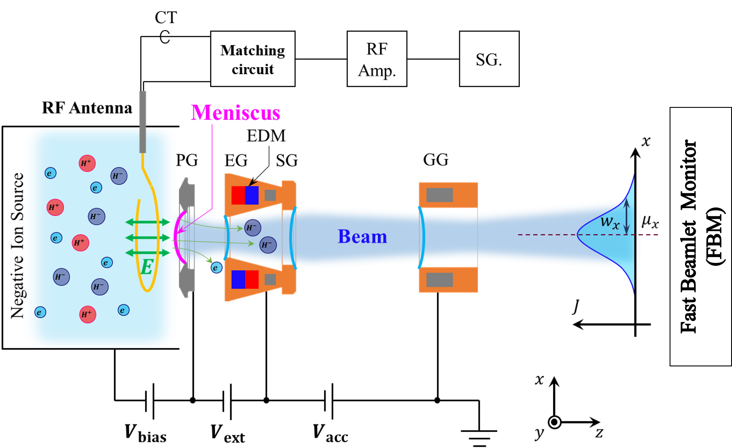
The experiment was carried out with a negative ion beam test stand at the National Institute for Fusion Science (NIFS-NBTS), and a research development negative ion source (NIFS-RNIS) was utilized, which is a one-third scaled negative ion source for the Large Helical Device (LHD). The accelerator configuration was almost identical to that of the negative ion source of the LHD, a circular multi-aperture for the plasma grid (PG), an extraction grid (EG) with an electron deflection magnet, a steering grid (SG) and a multi-slot type grounded grid (GG). Negative ions were produced mainly by the surface process on a caesium-seeded PG surface.
A schematic of this experiment is shown in Fig. 1. A Rogoski coil-type RF antenna was installed into NIFS-RNIS and the distance from the PG was around 5 mm. The RF electric field applied by the antenna in this experiment was perpendicular to the PG, which is considered to be the same configuration as the RF negative ion source configuration. The RF signal produced by a signal generator was amplified by a solid-state RF amplifier with a factor of (a gain of 60 dB) and the maximum power was 1 kW, which was typically of the arc discharge power (kW), resulting in negligible perturbation of the plasma density in this experiment. The RF power to the antenna was monitored by a current transformer (CT) with high-time resolution inserted between the antenna and the impedance-matching circuit. The maximum RF electric field is roughly 3 kV/m with the RF power to the antenna of 1 kW and with the frequency of 1MHz. A PG mask was utilized to make a single isolated beamlet. The beamlet profile was measured with a fast beamlet monitor (FBM) with a time resolution of 25 MHz. The FBM was installed at 1 m downstream from the GG.
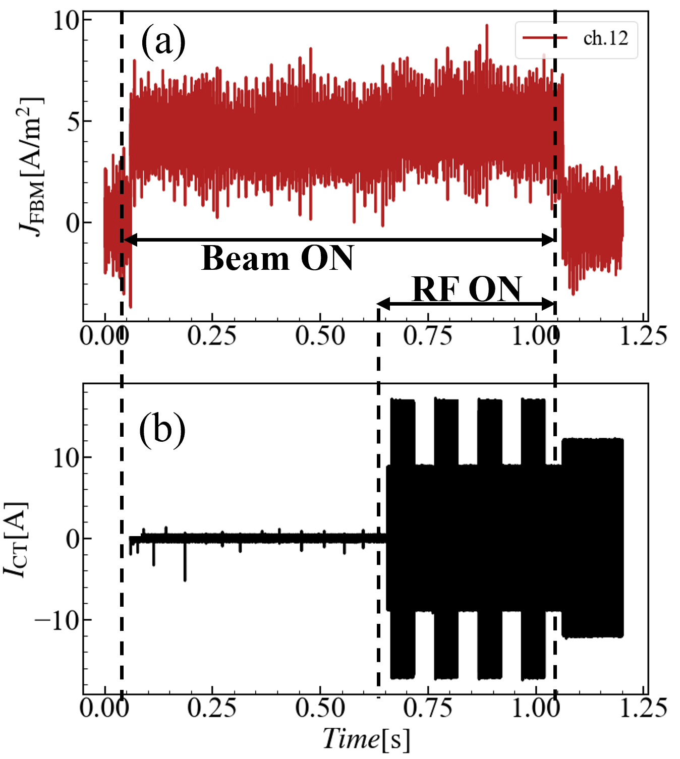
After the commissioning operation with caesium seeding, a negative ion beam acceleration with the perturbation RF field was carried out. The negative ion beam duration was 1 sec, and the perturbation RF was applied during the last one-third period of the beam. The RF power was modulated in time to investigate the RF power dependence. A typical waveform of the beam and RF perturbation is shown in Fig.2.
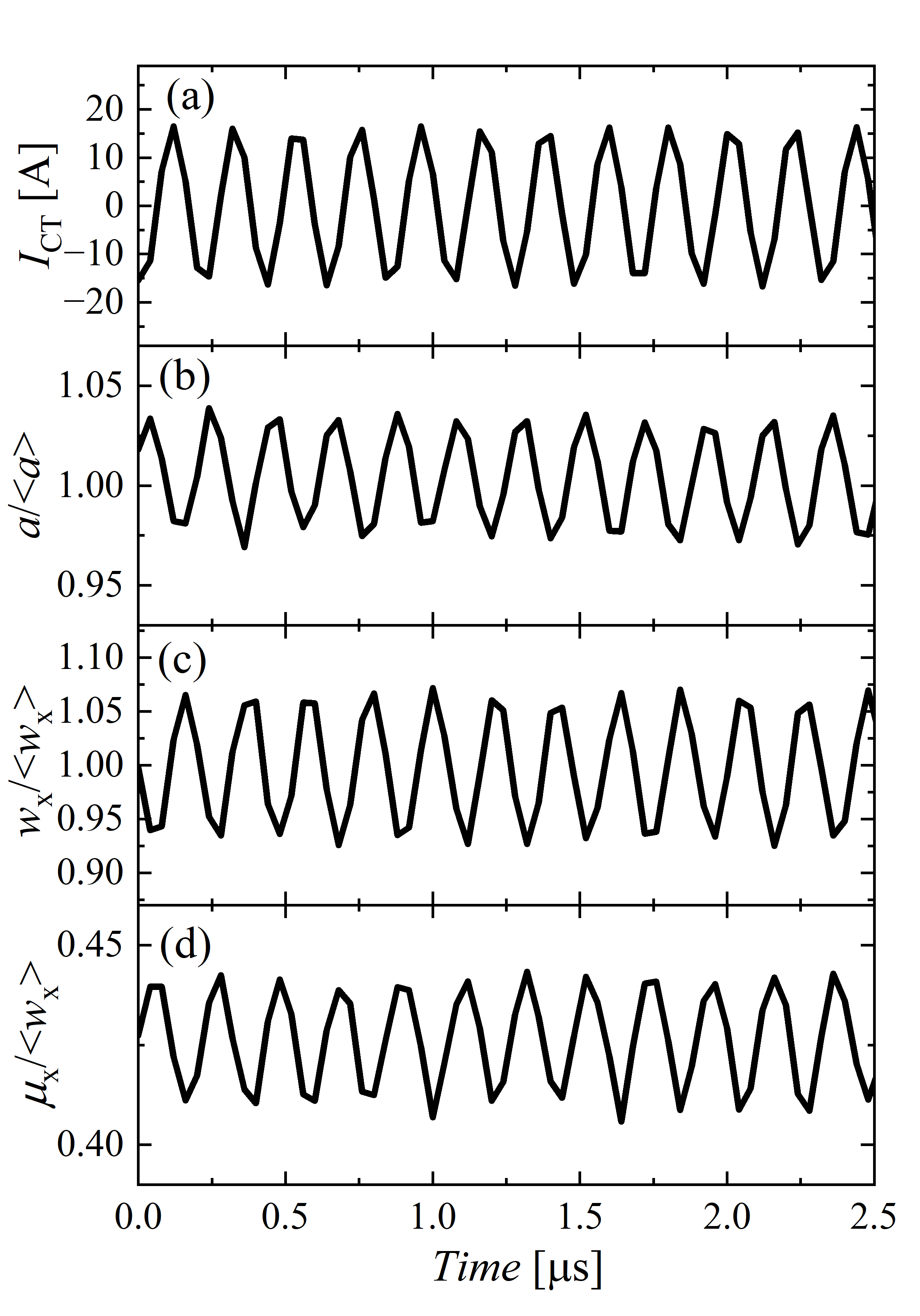
In order to investigate the beamlet behavior, a horizontal beamlet profile was analyzed with Gaussian fitting,
| (1) |
where , , and were the peak current density, the position of the beamlet center, the e-holding half width of the beamlet and the offset, respectively. The time evolution of the parameters obtained by the Gaussian fitting is shown in Fig.3. An RF with a frequency of 4.74 MHz was applied to the plasma near the PG and the CT signal is shown in Fig. 3(a). The oscillations with the perturbation RF frequency were observed in all three parameters, , , and , which are shown in Fig.3(b)-(d). The peak-to-peak amplitude of the beamlet width oscillation was up to of the averaged beamlet width, which reflects a change in the beam focus. The oscillation amplitude of the beamlet center position was up to of the averaged beamlet width, which also directly degraded the beam focusing.
Regarding the plasma production effect, the total current of the isolated beamlet could not be measured in this experiment because of the limited profile measurement in the vertical direction. However, the out-of-phase relation between the beamlet amplitude oscillation and the beamlet width oscillation indicates that the total current oscillation is small. Another piece of evidence is that no oscillation with the second harmonic frequency was observed. Therefore, the plasma production effect is considered to be negligible in this experiment.
In the case of RF positive ion sources, these oscillations were not observed in a core region of positive ion beamlet, in which the perturbation RF was applied between the PG and the plasma [24]. This is consistent with the fact that the beam divergence angle of the RF positive ion source is almost identical to that of the filament-arc positive ion source. Therefore, the beamlet oscillations observed in this experiment are considered to be a cause of the larger beam divergence angle of the RF negative ion source. In order to improve the beam focusing, the investigation of the dynamic response characteristics of the negative ion beamlet to the RF perturbation is very important.
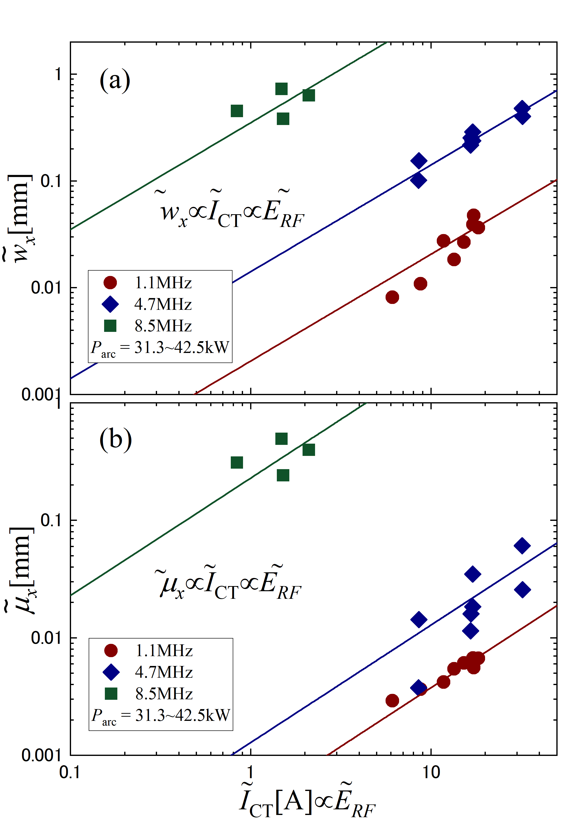
The RF amplitude dependence and the RF frequency dependence of the beamlet response were investigated and summarized in Fig.4. Three frequencies of 1.1 MHz, 4.7 MHz and 8.5 MHz were plotted, and the responses of the beamlet width increased almost linearly with the antenna current. The trend of the beamlet center position looks similar. The RF amplitude dependencies suggest that the meniscus responds linearly to the perturbation RF electric field because the RF electric field induced by the antenna is proportional to the RF current flowing through the antenna. It is considered that the RF electric field was superposed to the sheath electric field, and the response of the meniscus to an external perturbation with a small amplitude might be linear. It should be emphasised that the lower frequency might give a solution to mitigate the beamlet oscillation. In the lower frequency range from 1.1 MHz to 4.7 MHz, the oscillation amplitude of the beamlet seems to be proportional to the frequency (Faraday’s law of induction). Therefore, further mitigation might be possible with lower frequency. In the high frequency regime from 4.7 MHz to 8.5 MHz, the frequency dependence became stronger. The different frequency dependence would be considered by the change of coupling between the antenna and the plasma, however, further investigation is necessary.
Here, we discuss the perveance dependence of the beamlet dynamics based on the experimental observations, which are shown in Fig. 4, in which . We assume that the beamlet dynamics were determined by the response of the meniscus. In the case of conventional perveance dependence, the beamlet width is determined by the balance between the penetration of the electric field from the beam extraction region to the plasma and the Debye shielding effect of the ion source plasma. When an external perturbation is applied and the meniscus responds linearly, the change in beamlet width should depend on the gradient of the perveance curve,
| (2) |
where and are the perturbation RF electric field amplitude and the perveance (, where is the beam current and is the extraction voltage), respectively. The idea of eq. 2 is sketched in Fig. 5. It should be noted that the corresponds to the oscillation of the meniscus and is not .
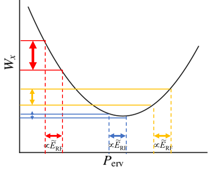
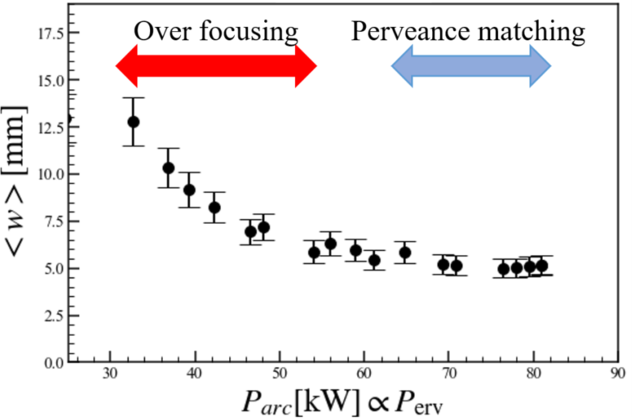
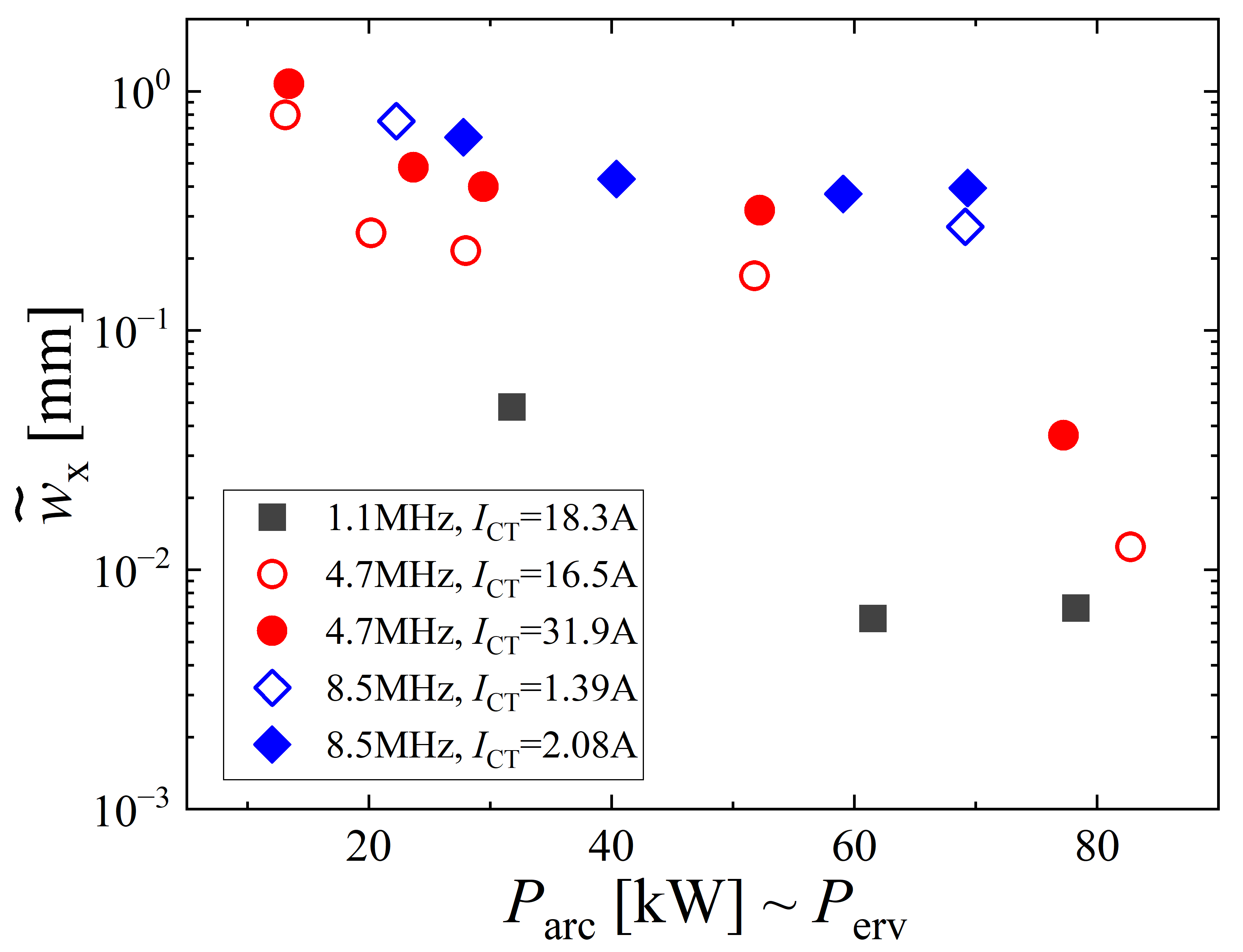
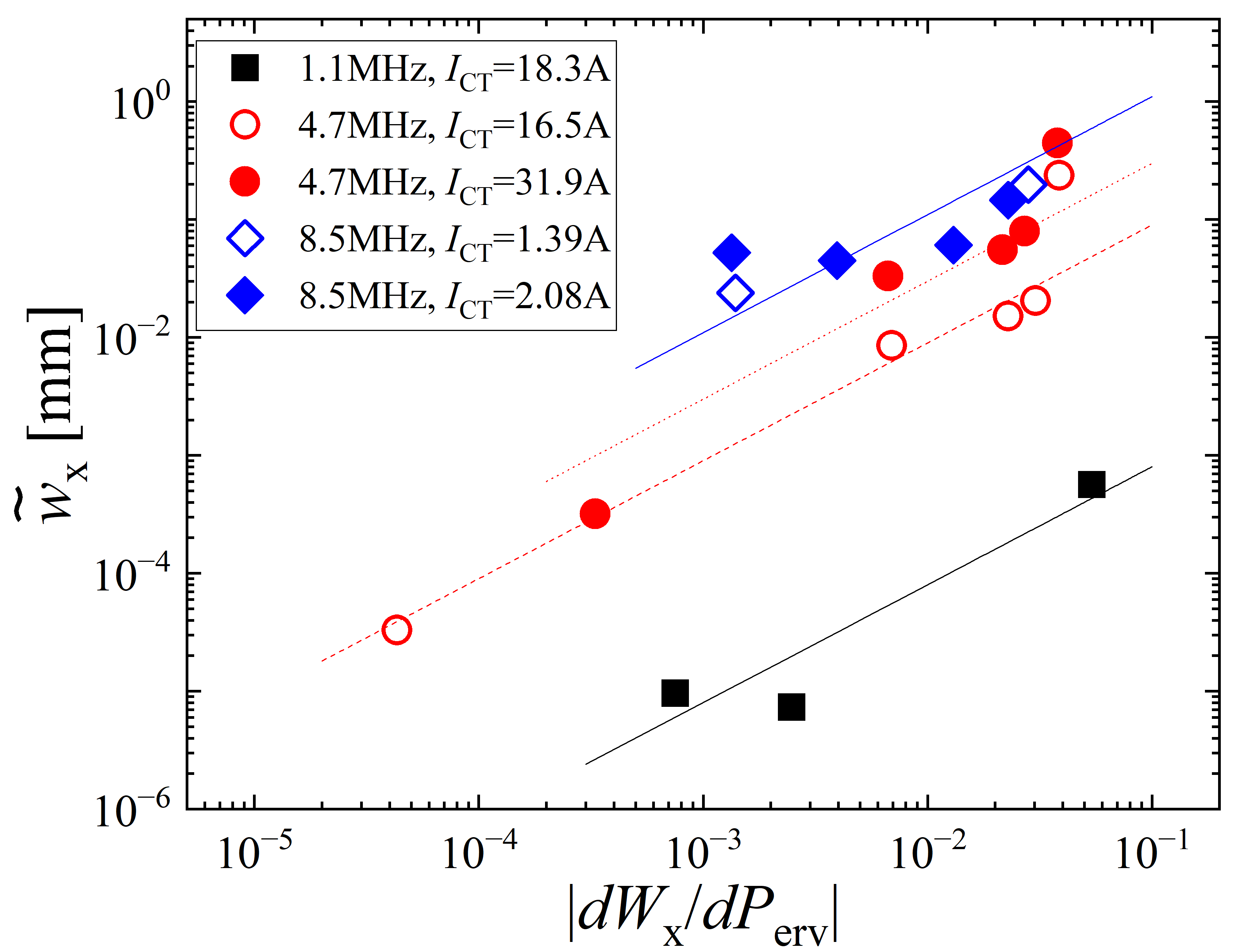
Figure 6 shows the perveance dependence of the beamlet width without the RF perturbation. One can see the perveance matching and over-focus regions due to the weak Debye shielding effect. A similar dependence can be seen in the oscillation amplitude of the beamlet width when RF perturbation is applied, which is shown in Fig. 7. In order to investigate the validity of the hypothesis shown in eq. 2, the amplitude of the beamlet width oscillation is compared with the gradient of the perveance curve , which is shown in Fig. 8. One can see the almost linear relation between the oscillation amplitude of the beamlet width and the gradient of the perveance curve when the RF power is fixed. This indicates that the oscillation of the beamlet width can be understood by the direct response of the sheath boundary to the perturbation RF electric field, which is modelled by eq. 2. The RF frequency dependence is also clearly seen, and the lower RF frequency provides the smaller amplitude of the beamlet width oscillation. From the viewpoint of the beam focusing, it should be noted that the oscillation of the beamlet width can be minimized at the perveance matched condition, where the gradient of the perveance curve is zero ().
In this letter, the direct effect of the RF field on beamlet focusing has been experimentally investigated. Oscillations of the beamlet width and of the beamlet center position were observed when the perturbation RF was applied to the plasma near the PG aperture. In comparing the RF positive ion sources, the larger beam divergence in RF negative ion sources is attributable to the oscillation of the meniscus and resulting in the oscillations of the beamlet width and position. The physics mechanism of the different responses of the meniscus is still an open issue.
The perveance dependence of the oscillation of the beamlet width was demonstrated and it was found that the beamlet width oscillation could be reduced at low RF frequency and at the perveance matching condition. It should be noted that the importance of the perveance matching is more significant in the RF negative ion source than in the filament-arc negative ion source.
The oscillation of the beamlet center is considered to be caused by the oscillation of the asymmetric meniscus. Although the PG aperture geometry is circularly symmetric, the magnetic field for electron deflection may break the symmetry of the particle dynamics in front of the PG aperture [18, 21-23], where the ion Larmor radius is in the same order as the aperture diameter. In order to mitigate the oscillation of the beamlet center, some modifications of the PG aperture geometry to cancel the asymmetry of the meniscus seem to make sense.
Quantitative evaluation of the beamlet response to the RF field in an ITER-relevant configuration of the RF negative ion source and a dedicated design study of the PG aperture configuration are very important researches to improve the beam focusing of RF negative ion sources and expand the application of the negative ion beams.
Acknowledgements.
One of the authors (K.N.) would like to thank Dr. W. Kraus (Max Planck Institute for Plasma Physics), Dr. T. Sasaki (Nagaoka University of Technology), Dr. K. Shinto, Dr. T. Shibata (KEK) and Dr. M. Wada (Doshisya University) for the fruitful discussions and engineering staff of NBI group at NIFS for their support of the experimental setup and the beam operations. This research was partially supported by NIFS(NIFS23KIIR023) and JSPS KAKENHI (17H03002, 18KK0080). ….-
[1]
R.S. Hemsworth, D. Boilson, et al., New J. Phys., 19, 025005 (2017).
-
[2]
U. Fantz, S. Briefi, A. Heiler, C. Wimmer and D. Wunderlich, Frontier in Physics, 9, 709651 (2021).
-
[3]
M. Barbisan, B. Zaniol, et al., Plasma Phys. Control., Fusion, 63, 125009 (2021).
-
[4]
A. Hurbatt, F. Bonomo, et al., AIP Advances, 11, 025330 (2021).
-
[5]
L. Hu et al., Fusion Eng. Des., 54, 321 (2001).
-
[6]
K. Tsumori, et al., Rev. Sci. Instrum., 79, 02C107 (2008).
-
[7]
K. Tsumori, et al., Rev. Sci. Instrum., 81, 02B117 (2010).
-
[8]
P. Veltri, et al., Rev. Sci. Instrum., 87, 02B908 (2016).
-
[9]
N.D. Harder, et al., Proceedings of the 29th IAEA-FEC, IAEA-CN-316-1882, 16-21 October 2023, London, United Kingdom.
-
[10]
C. Wimmer, et al., The 20th International Conference on Ion Sources, 17-22 September 2023.
-
[11]
U. Fantz, et al., Proceedings of the 29th IAEA-FEC, IAEA-CN-316-1794, 16-21 October 2023, London, United Kingdom.
-
[12]
P. Veltri, N. Den Harder, et al., 8th International Symposium on Negative Ions, Beams and Sources, Padova, Italy, Oct. 2-7, 2022.
-
[13]
S. Mochalskyy, U. Fantz, et al., Nucl. Fusion, 56, 106025 (2016).
-
[14]
T. Kalvas, O. Tarvanien, et al., Rev. Sci. Instrum., 81, 02B703 (2010).
-
[15]
A. Ueno et al., Rev. Sci. Instrum., 91, 033312 (2020).
-
[16]
M. Ichikawa, et al., AIP Conf. Proc.1869, 030024 (2017).
-
[17]
Y. Haba, K. Nagaoka, et al., New J. Phys. 22, 023017 (2020).
-
[18]
M. Kisaki, K. Nagaoka, et al., Nucl. Fusion, 62, 106031 (2022).
-
[19]
T. Shibata, et al., AIP Conf. Proc. 2373, 050002 (2021).
-
[20]
M. Wada et al., 8th International Symposium on Negative Ions, Beams and Sources, Padova, Italy, Oct. 2-7, 2022.
-
[21]
R. Gutser, D. Wunderlich U. Fantz and NNBI-Team, Plasma Phys. Control. Fusion, 51, 045005 (2009).
-
[22]
G. Fubiani, L. Garrigues and J.P. Boeuf, Phys. Plasmas, 25, 023510 (2018).
-
[23]
K. Miyamoto, K. Nagaoka, A. hatayama, et al., J. Phys. Conf. Series, 2244, 012040 (2022).
-
[24]
K. Takahashi, et al., New J. Phys., 21, 093043 (2019).