Bistable microbeam-based airflow sensor with piezoresistive snap-through detection
Abstract
We report on the first implementation of a piezoresistive interrogation in a bifurcation-based airflow velocity sensor. The resistivity changes in an entire beam are measured to detect snap-through transitions in a bistable double-clamped microbeam that is affected by airflow and serves as a sensing element. The flow velocity is extracted by monitoring the critical voltages of snap-through transitions. Piezoresistive sensing is especially suitable for the responses monitoring of the exposed to the environment, free-standing heated microbeam sensor, where optical, piezoelectric, or electrostatic interrogation methods are not applicable. Our digital sensor has lower power consumption and higher sensitivity ( V/m/s) than typical analog micro-hot-wire anemometers. Our results indicate that the suggested approach is a promising and reliable method for a flow sensor.
The field of microscale flow sensors has garnered significant research attention within the micro-electro-mechanical-systems (MEMS) community. Ho and Tai (1998) Hot-wire and hot-film sensors are the most commonly used types. Kuo, Yu, and Meng (2012) These sensors measure the heat loss in their elements caused by thermal convection generated by the surrounding fluid, which is directly related to the flow velocity and, in some cases, the flow direction. Kim, Nam, and Park (2004) Despite recent advancements in flow sensing using MEMS thermal sensors, challenges remain, including unwanted heat leakage, low sensitivity, and high power consumption. Ejeian et al. (2019)
Recently, we introduced a new flow measurement principle, which exploits the intrinsic coupling between the flow and the electrothermal and mechanical nonlinear behavior of bistable beams. Krylov et al. (2018) The initially curved double-clamped microbeam exhibits unique bistable behavior and can be in two stable states under the same load. This feature gives the beam exceptional sensitivity to external stimuli near the stability limits near the critical points, making it an ideal candidate for a flow sensor. The mechanical structure is pushed to its stability limits and is exceptionally responsive to even the smallest changes in heat transfer caused by flow. This device has the potential to offer increased velocity sensitivity, reduced power consumption, and improved robustness compared to traditional anemometer-type devices. Krylov et al. (2018); Kessler, Liberzon, and Krylov (2020, 2021); Litvinov et al. (2023).
While bifurcation flow sensors have shown promise, their integration remains unexplored. One of the central challenges is developing a reliable mechanical response detection approach suitable for implementation in an integrated stand-alone device. In our previous studies, Laser Doppler Vibrometry (LDV) was used to monitor the response of the microbeam. Krylov et al. (2018); Torteman et al. (2019); Kessler, Liberzon, and Krylov (2020, 2021); Litvinov et al. (2023) Although LDV sensing is suitable in a laboratory environment Moran et al. (2013), it cannot be implemented in the integrated stand-alone sensors. Electrostatic Alattar et al. (2023) or piezoelectric sensing is also less practical, as closely spaced electrodes or additional piezo-layers can negatively affect the flow sensor functionality. Li et al. (2020) Piezoresistive pressure sensors are well known and rely on materials that change electrical resistance when subjected to stress or strain Tufte, Chapman, and Long (1962). Piezoresistive sensing has been widely used in MEMS devices, allowing them to avoid additional design complexity. Fiorillo, Critello, and Pullano (2018); Barlian et al. (2009); He and Yang (2006)
The piezoresistive sensing using a nanowire-type gauge was recently successfully implemented in a nano-electro-mechanical-system (NEMS)-based gyroscope (see Dellea, Rey, and Langfelder (2017)). In mechanical flow sensors, the piezoresistive effect is often exploited to detect deformations of cantilever-type structures caused by drag or lift forces. Svedin N (2003); Mathew and Ravi Sankar (2018); Zhang et al. (2010); Abolpour Moshizi et al. (2022)
This paper aims to present a simple yet reliable method for detecting the snap-through transitions in a bistable double-clamped microbeam as a bifurcation-based airflow velocity sensor. Robust detection of the snap-through transitions using the piezoresistive effect of the entire microbeam proved to be the most suitable sensing approach. This study is essential to realizing a fully integrated MEMS flow sensor with enhanced performance.
A double-clamped microbeam of length , width , thickness , and initial midpoint elevation is fabricated of highly doped single crystal Si using the SOIMUMPs™ process. Krylov et al. (2018); Kessler, Liberzon, and Krylov (2020, 2021); Litvinov et al. (2023) The initially curved bell-shaped microbeam is shown in Fig. 1(a,b).
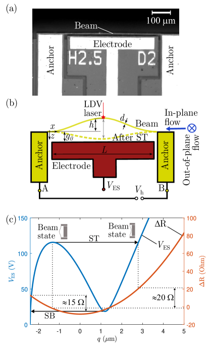
The nominal (as designed) initial shape of the beam is defined by lithography and is described by the function (where is the first bucking mode of a straight beam). The beam’s dimensions are provided in Table 1. The electrostatically actuated beam is designed to deflect in the in-plane (parallel to the substrate) -direction.
| Parameter | Size (m) |
|---|---|
| Length, | |
| Width, | |
| Thickness, | |
| Initial elevation, | |
| Beam-electrode distance, |
The operating principle of this flow sensor can be summarized as follows: the voltage applied to the electrode (shown in Fig. 1,(b)) influences the electrostatic force acting on the beam and causes the beam to be attracted to the electrode. Exceeding a critical snap-through (ST) value causes a dynamic transition from the first to the second stable equilibrium, as displayed in Fig. 1(b, left axis). The reduced order model development details are given in the Supplemental Material. The beam undergoes snap-back (SB) when the voltage decreases below the lower threshold and the beam releases to its initial state. Applying the voltage between the endpoints of the beam (points A and B) results in the Joule’s heating of the beam, an increase of the beam’s curvature and the more significant split between the critical voltages ( and ) values. Litvinov et al. (2023) Finally, the interplay between Joule’s heating and airflow-induced cooling allows for determining airflow velocity by measuring and . The ability to reliably and accurately detect the ST and the SB events is critical for the flow sensor functionality and performance. The central objective of this research was to develop a robust snap-through and snap-back transition detection method.
The change in resistance of the entire microbeam due to transitions (ST and SB) was first estimated using the model. The transition between the equilibrium states caused a shift in the beam’s displacement and, as a consequence, a change in the electrical resistance of the beam, as shown in Figure 1(c, right axis). In the framework of the single degrees of freedom, reduced order (RO) model, the beam’s mechanical response was parameterized by the midpoint displacement . In agreement with the model prediction, the resistance change is and for the ST and SB transitions, respectively, which could be easily detected in the experiment.
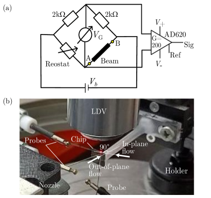
The experimental methodology implemented in the present work aligns with our previous study. Litvinov et al. (2023) The heating voltage is applied between the endpoints A-B (see Fig. 1(b)) using Wheatstone’s bridge to objectively discern the influence of the transition on the beam resistance. Under the condition that the bridge is balanced, a voltage of is applied to the beam (see the electrical circuit in Fig. 2(a)). To amplify the indicator voltage from the Wheatstone bridge, an instrumental voltage amplifier (AD620) is used. To connect the device to the electrical circuit, needle probes are used and placed on the anchors of the beam and the electrode, with the aid of a video camera (UI-6250SE-M-GL, IDS) and a horizontally mounted tube microscope (Navitar).
During the experiments, a ramp signal is applied using a Tektronix AFG3022C waveform generator and amplified by using a Trek PZD350A signal amplifier. The amplified voltage is then used to apply an actuating voltage between 0 and 135 V to the electrode. Actuation loading and unloading cycles are conducted to determine the values of and using the piezoresistive effect. The National Instruments USB-6363 data acquisition system digitizes the voltage ramp signal , the signal garnered from the LDV system (Polytec), and the piezoresistive voltage signal. This allowed all three signals to be synchronized. A 60-second signal is recorded at a sampling rate of 5 KHz. A ramp frequency of 1 Hz is set to collect statistics for 60 events of and , from which mean and standard error are calculated.
To demonstrate the effectiveness of the flow sensing, we attached the chip with the beam device to a 3D-printed plastic holder 50 mm in length. This allowed for flow access to the microbeam, as shown in Fig. 2(b). The flow was either in-plane, directed along the beam’s axis and parallel to the chip, or out-of-plane, in the direction perpendicular to the chip (see Figure 2(b)). To control the airflow velocity, a pressure gauge (P-30PSIG-D/5P, Alicat) monitors the pressure in the air supply system. A rectangular nozzle (1" High Power, EXAIR) creates a wide, uniform jet airflow directed at the microbeam from 40 mm away. The air supply is calibrated with a commercial anemometer (CTV 110, Kimo).
Figure 3(a) illustrates the electrostatic voltage ramp used to trigger the beam’s bistable behavior. Figure 3(b) represents the midpoint velocity measurement of the beam using LDV, showing two distinct peaks that correspond to ST and SB events. The laser beam of the LDV system is focused at the center of the microbeam. The high speed at which the beam moves during the ST causes the LDV system to detect a spike in Figure 3(b) that reflects the beam midpoint’s high-velocity level. In this sense, LDV is a validated and reliable reference method to determine ST and SB events.
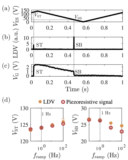
The piezoresistive signal of the microbeam stimulated by a ramp electrostatic voltage is shown in Figure 3(c). The ST and SB jumps cause a rapid increase and decrease in the resistance of the entire beam. The change in resistance at the SB transition is slightly lower than at the ST transition, consistent with the model prediction (Fig. 1(c)). As suggested by Fig. 3(c), the ST and SB jumps can be easily detected utilizing the the signal monitoring. We use the first derivative of the signal and the level-crossing approach to detect these events accurately. Our results clearly show that the piezoresistivity signal is consistent with the LDV signal and can be used to detect ST and SB events. However, it is crucial to understand how the ramp electrostatic voltage frequency affects the ability of piezoelectric sensing.
The effect of the frequency of the electrostatic voltage ramp on the detection of ST&SB is shown in Figure 3(d). The results based on LDV and piezoresistive data show that ST/SB voltages are weakly dependent on the frequency of the electrostatic voltage ramp. Increasing the ramp frequency results in a mismatch between the data obtained from the piezoresistivity signal and the LDV-based data. This is likely due to the frequency limitations of the operational amplifier. Meanwhile, experimental findings indicate that raising the frequency beyond 600 Hz renders it unfeasible to sustain the bistability behavior of a beam of this size.Kessler, Liberzon, and Krylov (2021) The results in the following are shown at a ramp frequency of 1 Hz.
We also investigated the effect of beam overheating on the sensing capability based on monitoring and voltages. To accomplish this, we varied the voltage across the bridge from 0 to 6 V without flow and analyzed the functional relationship between and , as shown in Figure 4. Our observations showed that as the voltage increased, there was a corresponding increase in values and a decrease in values, consistent with our previous research. Litvinov et al. (2023) Conversely, decreasing the bridge voltage reduced the amplitude of the beam piezoresistivity signal (inset in Figure 4).
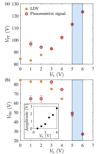
However, a limitation of the piezoresistive method is reached for <3 V, as the values of ST and SB voltages obtained with this method began to diverge from those obtained with LDV. We expect that the values obtained with LDV remain valid. Still, the limitation of the piezoresistive approach arises because the measurement is subject to significant uncertainty due to the higher noise level and the decreasing amplitude of the piezoresistive signal (inset in Figure 4). On the other hand, increasing the level above 7 V resulted in a latching effect, where the beam remains in the switched configuration at zero actuation voltage. The SB is not achieved in this regime. . Litvinov et al. (2023)
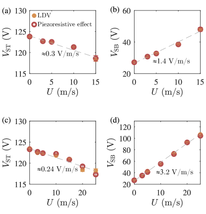
Figure 5 shows the values of and as a function of velocity and in the cases of in-plane and out-of-plane flow directions, respectively. Two independent sensing methods, the LDV and the piezoresistivity of the entire beam, are used to determine these values. The results demonstrate a good correlation between the output signals acquired using both sensing methods. This indicates that the piezoresistive signal can be the primary sensing method in a stand-alone bistable beam-based velocity sensor.
As previously shown Krylov et al. (2018); Kessler, Liberzon, and Krylov (2020); Litvinov et al. (2023), the sensitivity to flow velocity at the voltage corresponding to the SB effect is much higher than the ST voltage values. This is a consequence of the nonlinear electrostatic force acting on the beam as it approaches the electrode. Indeed, the sensor’s sensitivity varies from 0.24 to 0.3 V/m/s for VST values and from 1.4 to 3.2 V/m/s for values. The maximal sensitivity of 3.2 V/m/s corresponding to value is registered for the out-of-plane flow direction. Such a significant difference between the in-plane and out-of-plane flow configurations is due to the interaction of the flow with the bottom surface of the beam near the electrode. It should be noted that when measuring velocities above 25 m/s, the values for and begin to converge and become indistinguishable. This limits the range of velocity measurements for a given level but does not fundamentally prevent velocity measurements from being made at higher levels with this device. It is possible to design stiffer beams with higher initial elevation, use wider beams, or increase the overheating ratio by voltage.
We emphasize that the sensing is achieved by measuring the same electric current used for the beam’s heating, controlled by the heating voltage between the beam’s ends. No additional layers are deposited on the sensing beam itself. This new method enables the direct detection of ST/SB using the bridge signal, making the sensor suitable for field testing.
In summary, we present a simple, reliable, and robust approach to accurately detect snap-through transitions in a bistable, double-clamped microbeam applied as a bifurcation-based airflow velocity sensor. Our experiments demonstrate the sensor’s sensitivity to wind speed and direction, indicating its potential as a reliable flow sensor. Compared to the standard analog hot-wire micro anemometers Ejeian et al. (2019), our digital sensor offers significant advantages, including low power consumption and high sensitivity to the velocity (3 V/m/s). Overall, our findings suggest that this sensing method holds great promise for practical applications in flow sensing.
The authors acknowledge the financial support of the Israeli Innovation Authority, NOFAR program, and Rafael Advanced Defense Systems Ltd. S. Krylov believes the support of the Henry and Dinah Krongold Chair of Microelectronics.
References
- Ho and Tai (1998) C.-M. Ho and Y.-C. Tai, “Micro-electro-mechanical-systems (mems) and fluid flows,” Annual review of fluid mechanics 30, 579–612 (1998).
- Kuo, Yu, and Meng (2012) J. T. Kuo, L. Yu, and E. Meng, “Micromachined thermal flow sensors—a review,” Micromachines 3, 550–573 (2012).
- Kim, Nam, and Park (2004) S. Kim, T. Nam, and S. Park, “Measurement of flow direction and velocity using a micromachined flow sensor,” Sensors and Actuators A: Physical 114, 312–318 (2004).
- Ejeian et al. (2019) F. Ejeian, S. Azadi, A. Razmjou, Y. Orooji, A. Kottapalli, M. E. Warkiani, and M. Asadnia, “Design and applications of mems flow sensors: A review,” Sensors and Actuators A: Physical 295, 483–502 (2019).
- Krylov et al. (2018) S. Krylov, Y. Kessler, E. Benjamin, B. Torteman, and A. Liberzon, “Micromechanical bistable flow sensors,” in 2018 IEEE SENSORS (IEEE, 2018) pp. 1–4.
- Kessler, Liberzon, and Krylov (2020) Y. Kessler, A. Liberzon, and S. Krylov, “Flow velocity gradient sensing using a single curved bistable microbeam,” Journal of Microelectromechanical Systems 29, 1020–1025 (2020).
- Kessler, Liberzon, and Krylov (2021) Y. Kessler, A. Liberzon, and S. Krylov, “On sampling rate limits in bistable microbeam sensors,” Journal of Microelectromechanical Systems 30, 980–989 (2021).
- Litvinov et al. (2023) I. Litvinov, D. Refaeli, A. Liberzon, and S. Krylov, “Effect of overheat and direct flow loading on the MEMS bistable flow sensor,” (2023), arXiv:2312.12860 [physics.app-ph] .
- Torteman et al. (2019) B. Torteman, Y. Kessler, A. Liberzon, and S. Krylov, “Electro-thermal excitation of parametric resonances in double-clamped micro beams,” Applied Physics Letters 115 (2019).
- Moran et al. (2013) K. Moran, C. Burgner, S. Shaw, and K. Turner, “A review of parametric resonance in microelectromechanical systems,” Nonlinear Theory and Its Applications, IEICE 4, 198–224 (2013).
- Alattar et al. (2023) B. Alattar, M. Ghommem, A. Elhady, F. Najar, and E. M. Abdel-Rahman, “Tracking of bifurcations and hysteresis in electrostatically actuated resonators by motion-induced current,” Mechanical Systems and Signal Processing 204, 110808 (2023).
- Li et al. (2020) J. Li, L. Fang, B. Sun, X. Li, and S. H. Kang, “Recent progress in flexible and stretchable piezoresistive sensors and their applications,” Journal of the Electrochemical Society 167, 037561 (2020).
- Tufte, Chapman, and Long (1962) O. N. Tufte, P. W. Chapman, and D. Long, “Silicon Diffused-Element Piezoresistive Diaphragms,” Journal of Applied Physics 33, 3322–3327 (1962).
- Fiorillo, Critello, and Pullano (2018) A. Fiorillo, C. Critello, and S. Pullano, “Theory, technology and applications of piezoresistive sensors: A review,” Sensors and Actuators A: Physical 281, 156–175 (2018).
- Barlian et al. (2009) A. A. Barlian, W.-T. Park, J. R. Mallon, A. J. Rastegar, and B. L. Pruitt, “Semiconductor piezoresistance for microsystems,” Proceedings of the IEEE 97, 513–552 (2009).
- He and Yang (2006) R. He and P. Yang, “Giant piezoresistance effect in silicon nanowires,” Nature nanotechnology 1, 42–46 (2006).
- Dellea, Rey, and Langfelder (2017) S. Dellea, P. Rey, and G. Langfelder, “Mems gyroscopes based on piezoresistive nems detection of drive and sense motion,” Journal of Microelectromechanical Systems 26, 1389–1399 (2017).
- Svedin N (2003) S. G. Svedin N, Kalvesten E, “A new edge-detected lift force flow sensor,” J Microelectromech S 12, 344–354 (2003).
- Mathew and Ravi Sankar (2018) R. Mathew and A. Ravi Sankar, “A review on surface stress-based miniaturized piezoresistive su-8 polymeric cantilever sensors,” Nano-micro letters 10, 1–41 (2018).
- Zhang et al. (2010) Q. Zhang, W. Ruan, H. Wang, Y. Zhou, Z. Wang, and L. Liu, “A self-bended piezoresistive microcantilever flow sensor for low flow rate measurement,” Sensors and Actuators A: Physical 158, 273–279 (2010).
- Abolpour Moshizi et al. (2022) S. Abolpour Moshizi, H. Moradi, S. Wu, Z. J. Han, A. Razmjou, and M. Asadnia, “Biomimetic ultraflexible piezoresistive flow sensor based on graphene nanosheets and pva hydrogel,” Advanced Materials Technologies 7, 2100783 (2022).
- Beckwith, Buck, and Marangoni (1982) T. G. Beckwith, N. L. Buck, and R. D. Marangoni, Mechanical measurements, Vol. 5 (Addison-Wesley New York, 1982).
- Harne and Wang (2013) R. L. Harne and K. Wang, “A review of the recent research on vibration energy harvesting via bistable systems,” Smart materials and structures 22, 023001 (2013).