Fault-tolerant quantum architectures based on erasure qubits
Abstract
The overhead of quantum error correction (QEC) poses a major bottleneck for realizing fault-tolerant computation. To reduce this overhead, we exploit the idea of erasure qubits, relying on an efficient conversion of the dominant noise into erasures at known locations. We start by introducing a formalism for QEC schemes with erasure qubits and express the corresponding decoding problem as a matching problem. Then, we propose and optimize QEC schemes based on erasure qubits and the recently-introduced Floquet codes. Our schemes are well-suited for superconducting circuits, being compatible with planar layouts. We numerically estimate the memory thresholds for the circuit noise model that includes spreading (via entangling operations) and imperfect detection of erasures. Our results demonstrate that, despite being slightly more complex, QEC schemes based on erasure qubits can significantly outperform standard approaches.
I Introduction
Quantum error correction (QEC) and fault-tolerant protocols [1, 2, 3] can benefit significantly from an ingenious design of qubits with tailored, often hardware-dependent, noise structure. For instance, a bosonic cat qubit [4, 5, 6, 7, 8] exhibits biased Pauli noise. Such noise can be readily exploited, e.g., by an appropriate variant of the surface code [9, 10, 11, 12, 13, 14, 15], resulting in greatly increased QEC thresholds and reduced qubit overheads of the associated QEC protocols.
Recently, another type of qubit, often referred to as an erasure qubit, has received significant attention. Several theoretical proposals have described how the erasure qubit can be straightforwardly realized with, e.g., neutral atoms [16], trapped ions [17] or superconducting circuits [18, 19], as well as several promising proof-of-principle experimental demonstrations [20, 21, 22, 23, 24]. The idea behind the erasure qubit is to engineer a qubit in such a way that its dominant noise is detectable erasures [25]. Importantly, the knowledge of locations of erasures can be efficiently leveraged by QEC protocols (that may be based on the surface code) and decoding algorithms, leading to high QEC thresholds and an improved subthreshold scaling of the logical error rate [26, 27, 28].
For QEC protocols to benefit from erasure qubits, the following requirements have to be satisfied: (i) a large erasure bias, defined as the ratio of the probability of an erasure to the probability of any other residual error within the computational subspace, (ii) an implementation of standard quantum circuit operations, including state preparation, unitary gates and readout, in a way that preserves an erasure bias, and (iii) the ability to perform an erasure check capable of reliably detecting erasures without introducing additional errors within the computational subspace. Thus, it appears that approaches based on erasure qubits, compared to the standard ones, are more challenging to implement. However, while there is an additional cost associated with, e.g., a careful design of the erasure check, once these additional building blocks are available, then new possibilities for optimized QEC protocols and fault-tolerant architectures open up.
In this article, we address the question of designing fault-tolerant architectures that are optimized for and make full use of erasure qubits. We start by introducing a formalism for QEC protocols with erasure qubits and express the corresponding decoding problem as the hypergraph matching problem. This, in turn, allows us to design decoding algorithms, which, in many relevant scenarios, may be based on the matching algorithm [29, 15]. We then focus on fault-tolerant architectures and find that erasure qubits are particularly suitable for a recently-introduced family of QEC codes, Floquet codes [30, 31]. In particular, in one realization of erasure qubits via the dual-rail encoding [32], the minimal set of quantum circuit operations necessary to implement Floquet codes consists of state preparation, readout, single-qubit gates and erasure checks (which also play the role of entangling operations). We discuss possible physical implementations of erasure checks in the context of superconducting circuits. To benchmark our scheme, we numerically estimate the memory thresholds of Floquet codes against circuit noise comprising erasures, Pauli errors and measurement errors (for readout and erasure checks). Lastly, we analyze further optimizations of Floquet codes that lead to the reduced qubit overhead, as well as find the smallest Floquet codes with distance two and four, which require, respectively, 4 and 16 qubits.
II QEC protocols with erasure qubits
Analyzing QEC protocols with erasure qubits poses some challenges. First, modelling each erasure qubit may require at least a three-level system. Second, quantum circuit operations might, in principle, introduce correlated coherent errors in the presence of erasures. Consequently, there seems to be little hope for efficient simulation methods akin to the ones used for stabilizer circuits [33, 34]. In addition, decoding algorithms do not typically consider erasures and their spread.
In this section, we describe how making certain simplifying assumptions allows us to efficiently decode and simulate QEC protocols with erasure qubits; see Appendix A for a detailed description of our formalism. In particular, we phrase the decoding problem as the hypergraph matching problem.
We emphasize that our formalism and numerical simulations go beyond the paradigm of erasure qubits. Namely, they can be used for QEC schemes with leakage, allowing us to quantify the potential gains from the ability to detect leakage [35, 36, 37].
II.1 Setting the formalism
To describe QEC protocols, we use quantum circuits that consist of the following standard single-qubit (1Q) and two-qubit (2Q) operations: (i) 1Q state preparation (of eigenstates of Pauli operators), (ii) 1Q readout (in any Pauli basis), (iii) 1Q Clifford gates, and (iv) 2Q controlled-Pauli gates, where , as well as the additional operations: (v) 1Q erasure checks, (vi) 1Q reset (of the erasure qubit), (vii) 2Q projective measurements of Pauli operators. We refer to such circuits as erasure circuits. In contrast, stabilizer circuits consist only of operations (i)-(iv) and (vii). An example of an erasure circuit is presented in Fig. 1.
(a)
(b)
To simulate QEC protocols, we first need to explicitly include all the erasure locations (where erasures may happen) into erasure circuits and then replace each ideal operation (i)-(vii) by its noisy counterpart. We realize the latter by following a standard procedure of adding appropriate Pauli noise after each operation and adding bit-flip noise to each outcome (for readout, erasure checks and projective measurements), as depicted in Table 1. To realize the former, we choose to insert one erasure location on each wire between each two consecutive operations (i)-(vii); see Fig. 1(b) for an illustration. The noise strengths could be arbitrary at every location, however, for the purposes of our analysis, we describe the noise by three parameters: , the erasure rate; , the Pauli error rate; and , the classical bit-flip noise rate.
| operation | ideal | simulated | ||||||
| state preparation | \qw | \qw | ||||||
| readout | \meter_ P | \Qcircuit@C=.8em @R=.7em | \gateEC | \meter_ P | ||||
| *+[F-:¡.9em¿]N(q) \cwx | \cw | \cw | ||||||
| \cw | ||||||||
| erasure check with reset | \qw | \Qcircuit@C=.8em @R=.7em | \gateEC | \gateR | \measureP(p) | \qw | ||
| \cw | ||||||||
| entangling gate | \Qcircuit@C=.8em @R=.7em | \multigate1G | \qw | |||||
| \qw | \Qcircuit@C=.8em @R=.7em | \multigate1G | \multimeasure1P(p) | \qw | ||||
| \qw | ||||||||
| projective measurement | \Qcircuit@C=.8em @R=.7em | \multigate1Π_PP | \qw | |||||
| \qw | \Qcircuit@C=.8em @R=.7em | \multigate1Π_PP | \multimeasure1P(p) | \qw | ||||
| \ghostΠ_PP | \ghostP(p) | \qw | ||||||
| \cw | ||||||||
In contrast to standard QEC protocols, with erasure qubits not only do we have Pauli noise that affects quantum circuits but also erasures. Erasures are probabilistic processes happening at erasure locations and taking the state from the computational subspace to some orthogonal subspace, which we refer to as the erasure subspace. Furthermore, erasures can spread (probabilistically) via 2Q operations. We envision the following two scenarios.
-
•
Erasure-erasure spread: an erasure spreads to another erasure.
-
•
Erasure-Pauli spread: an erasure spreads to a Pauli error.
One concrete realization of the erasure-Pauli spread, which we refer to as the erasure-depolarization spread, is when an erasure spreads to either Pauli , or , or , each with probability . In other words, any qubit affected by an erasure causes full depolarization of any other qubit that is involved in the same 2Q operation. In the rest of the article we focus on the erasure-depolarization spread.
The key part of QEC protocols with erasure qubits is the ability to detect erasures. Erasure detection can be achieved by either readout or erasure checks. Each erasure check performs a nondestructive measurement that distinguishes the states in the computational and erasure subspaces. For simplicity, in our numerical simulations in Sec. IV and Sec. V.1 we assume that each erasure check is immediately followed by reset of the erasure qubit that reinitializes it in the computational subspace (and do not include an erasure location in between the erasure check and reset). We envision the following two scenarios.
-
•
Conditional (active) reset that depends on the outcome of the erasure check (and possibly other previous erasure checks).
-
•
Unconditional (passive) reset that is independent of any erasure check outcome.
For concreteness, in either case we assume that the erasure qubit is reinitialized in the maximally mixed state in the computational subspace. We further assume that reset acts trivially on the computational subspace. In the rest of the article we focus on unconditional reset.
We emphasize that in our formalism we assume that the operations (i)-(vii) do not create coherences between the computational and erasure subspaces. This, in turn, allows us to efficiently sample from erasure circuits; see Sec. II.3 for details. Also, our assumption about the erasure-depolarization spread allows us to push erasures through entangling operations and model entangling operations as always acting on the computational subspace. We leverage this observation to express the decoding problem for erasure circuits as the hypergraph matching problem; see Sec. II.2 for details.
Our approach generalizes straightforwardly to leakage simulations as long as there are no coherences between the computational and leakage subspaces (regardless of the number of leaked levels), the only difference being the lack of erasure check operations; see Fig. 6(b)(e) and Fig. 14. When there are coherences, the simulation may become less efficient because we might not be able to use the stabilizer formalism to describe the relevant states.
II.2 Decoding problem for erasure circuits
Let us first describe the decoding problem for stabilizer circuits. In addition to the stabilizer circuit, we also need to specify a distribution of Pauli errors that are placed at spacetime locations between operations of the circuit and a set of detectors . By definition, a detector is a product of measurement outcomes in the circuit that is deterministic in the absence of errors and gives information about possible errors when triggered. The stabilizer circuit may describe the implementation of, e.g., a stabilizer code, where detectors are products of consecutive stabilizer measurements, or a Floquet code, where detectors are more complicated. Given detectors which are triggered after running the circuit, the decoding problem is to find a Pauli recovery which undoes the errors that occurred.
The decoding problem for stabilizer circuits can be phrased as a hypergraph matching problem. This formulation is particularly useful when the distribution of Pauli errors is either equal to or approximated by a product distribution of binary random variables, often referred to as error mechanisms. By definition, an error mechanism is a pair such that the Pauli error is inserted at specified spacetime locations in the circuit with probability . When occurs, it causes a subset of detectors to be triggered. If we then define a weighted hypergraph , where each hyperedge has weight , then the problem of finding the most likely error triggering a subset of detectors is equivalent to the minimum-weight hypergraph matching problem on , i.e., for a given subset of vertices , find a subset of hyperedges with lowest total weight , such that , where denotes the symmetric difference of sets. The recovery operator is the product of all Pauli errors (propagated to the end of the circuit) that correspond to the hyperedges in .
The decoding problem for erasure circuits is still to find a Pauli recovery. This time, in addition to the triggered detectors, we also have erasure check outcomes. In what follows, we describe a mapping of erasure circuits to stabilizer circuits, where erasures are converted into independent Pauli error mechanisms. This mapping, in turn, allows us to phrase the decoding problem for erasure circuits as a hypergraph matching problem.
We decompose the erasure circuit into segments. By definition, a segment is the worldline of a single qubit between two consecutive reset operations 111For brevity, we also refer to state preparation and readout as reset operations.; see Fig. 2(a) for an illustration. We also define the entangling operations of as those with nontrivial support on and the spacetime locations associated with as those immediately following the entangling operations of . To map to a stabilizer circuit with independent Pauli error mechanisms, we modify each segment of by removing the erasure checks and reset operations in and add appropriate error mechanisms at the locations associated with . This mapping is guaranteed by Lemma 1.
(a)
(b)
Lemma 1.
Let be a segment of an erasure circuit . Given the outcomes of erasure checks in , the distribution of errors introduced by erasures in is equivalent to a distribution of spacetime correlated Pauli errors that can be described by independent error mechanisms .
Proof.
The proof proceeds in three steps. First, we find the distribution of Pauli errors caused by erasures in the segment. This distribution can be described by disjoint events which are correlated depolarizing channels applied at different spacetime locations in , caused by the erasure-depolarization spread. Second, we show that this distribution can also be described by a product of independent events which are spacetime correlated depolarizing channels. Third, we decompose each of these spacetime correlated depolarizing channels into independent error mechanisms.
We start by introducing some notation. Let be the -th entangling operation in and be the spacetime location associated with placed after defined via , where and labels the qubit identified with ; see Fig. 2. For convenience, we use and to denote the first and second reset operations in , and define to be the location at after the second reset. In the case when is a 2Q projective measurement, we imagine the classical bit containing the outcome to be a qubit and to include that qubit. We also define
| (1) |
We want to find the distribution of Pauli errors caused by erasures in . Let be the event that it was first erased at any location in between and , where . When occurs, it causes all qubits connected to through subsequent entangling operations to be fully depolarized, i.e., fully depolarizing channels are added at spacetime locations . Note that are disjoint events. Given the erasure check outcomes (whose probability distribution depends on the erasure probabilities and the false positive and negative detection rates of the erasure checks in the segment ), we can calculate the posterior probabilities
| (2) |
We then obtain the distribution of Pauli errors by sampling disjoint events with probability and inserting fully depolarizing channels at whenever the corresponding event is sampled.
In the description of , we have disjoint events rather than independent ones. To obtain the desired description, we show that can also be obtained by sampling independent events , where is defined as a binary random variable with probability
| (3) |
and placing fully depolarizing channels at spacetime locations whenever is sampled. To do that, observe that for a composition of fully depolarizing channels at and is equivalent to the fully depolarizing channels at , since . Therefore, fully depolarizing channels are placed exclusively at iff we sample but no other for , which happens with probability
| (4) |
Finally, we further decompose the depolarizing channels resulting from the events into independent error mechanisms. Namely, for each we introduce error mechanisms, each corresponding to a different nontrivial Pauli error that can be placed at spacetime locations with probability
| (5) |
The resulting product distribution of independent error mechanisms is equivalent to . To show that, we use the same reasoning as in Claim 1 of Ref. [39]. The analysis there considered Pauli errors on qubits which occur at the same time, but the only necessary ingredient is that the set of possible errors under composition forms a group isomorphic to which is true in our case with . This concludes the proof. ∎
For the reader’s convenience, we recap the conversion of an erasure circuit into a stabilizer circuit with independent error mechanisms in Algorithm 1.
Input:
erasure circuit , erasure check outcomes
Output:
stabilizer circuit , error mechanisms
We finish this subsection with a few remarks.
- •
-
•
In many scenarios, e.g., the surface code or Floquet codes, the distribution of Pauli errors can be further approximated by a product of independent error mechanisms that trigger at most two detectors. Consequently, the decoding problem reduces to the graph matching problem, which is efficiently solvable [41].
-
•
The number of error mechanisms added for each segment in Algorithm 1 is exponential in the length of . If reset operations occur at constant time intervals in the erasure circuit , then the total number of added error mechanisms is proportional to the size of .
-
•
If reset operations occur between every entangling operation in the erasure circuit (as is the case in our numerical simulations), then the resulting error mechanisms are not time correlated and can simply be described by depolarizing channels; see Appendix B.
-
•
For simplicity, we focused on the scenario of the erasure-depolarization spread. The analysis for the deterministic erasure-erasure spread is similar. However, the probability of erasure between entangling operations may need to be conditioned on many erasure check outcomes, not just within one segment.
II.3 Sampling erasure circuits
We envision two ways of sampling from an erasure circuit for simulation purposes. In the first method, we use one bit of information per qubit to represent its erasure state. This allows us to efficiently simulate erasures, erasure checks and reset operations by sampling from the correct probabilities and updating this classical data. For the qubits in the computational subspace, we keep track of the stabilizers and update them after standard stabilizer circuit operations using the Gottesman-Knill theorem [33, 34]. When a qubit is erased, we randomize measurement outcomes involving it and depolarize qubits that interact with it through entangling operations.
Alternatively, we may simulate the circuit by first sampling all erasure check detection events. Conditioned on the results, we then use the results of Sec. II.2 to obtain stabilizer circuits that we can sample from. Each independent error mechanism in the resulting circuit can be simulated by adding a classical bit that determines whether or not the corresponding error is applied. However, this is often unnecessary because if the Pauli errors occur at the same time (as is the case for us; see Appendix B), it can be simulated by depolarizing channels. The advantage of this approach is that after obtaining the erasure detection events, the same circuit can be used for sampling and decoding.
III Scalable architecture with erasure qubits
In this section, we describe how a realization of erasure qubits via the dual-rail encoding naturally leads to a fault-tolerant architecture based on Floquet codes (which we briefly overview). Our approach is particularly well-suited for superconducting circuits. We also discuss possible hardware implementations of physical operations needed to realize Floquet codes.
III.1 From erasure qubits to Floquet codes
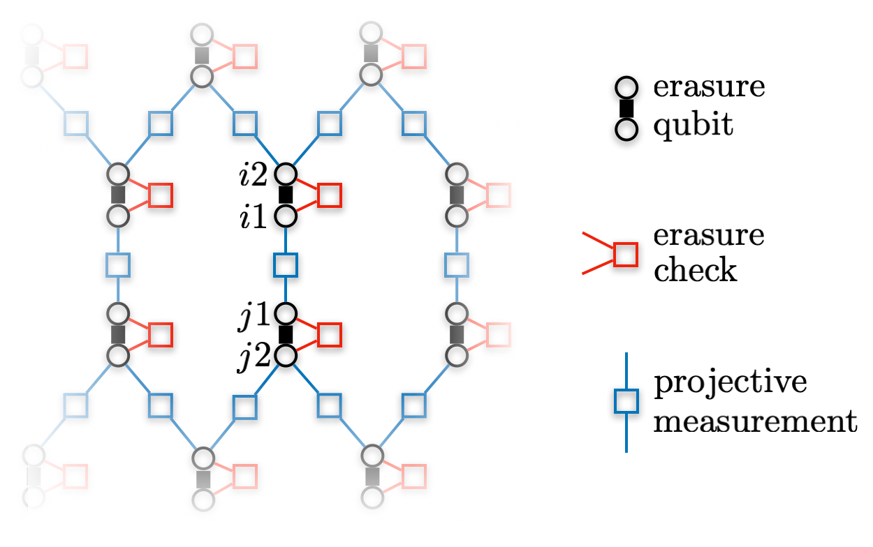
One of the simplest ways to realize the erasure qubit is via the dual-rail encoding
| (6) |
which is particularly well-suited for superconducting circuits. Namely, the dominant noise for this quantum computing platform is the amplitude damping noise [42, 43] that describes the energy relaxation from the excited state to the ground state . A single amplitude damping event can be detected as it maps any state of the erasure qubit to the state which is orthogonal to the computational subspace . Consequently, the effective noise afflicting the qubit is dominated by detectable erasures. We remark that a few recent experiments demonstrated the erasure qubit via the dual-rail encoding using either two transmons [23] or two 3D cavities [22, 24].
Observe that a projective measurement of a Pauli operator, where and label two qubits forming the erasure qubit via the dual-rail encoding, is sufficient to implement an erasure check; see Fig. 3. Namely, a measurement outcome implies that the state is outside the computational subspace , and the erasure qubit has suffered from an erasure. However, a projective measurement of a Pauli (or ) operator supported on qubits from two different erasure qubits and implements a Pauli measurement on their computational subspace. Therefore, the ability to perform projective measurements of Pauli operators, together with single-qubit Hadamard and phase gates on the computational subspace, is sufficient to implement erasure checks and Pauli , , measurements on the computational subspace. This, in turn, allows us to implement Floquet codes with erasure qubits (where we implicitly assume the capability of single-qubit state preparation and readout in the computational basis); see Fig. 3 for an illustration.
III.2 Floquet codes
| round | measure |
|---|---|
|
|
|
|
|
|
|
|
|
|
|
|
|
|
|
|
|
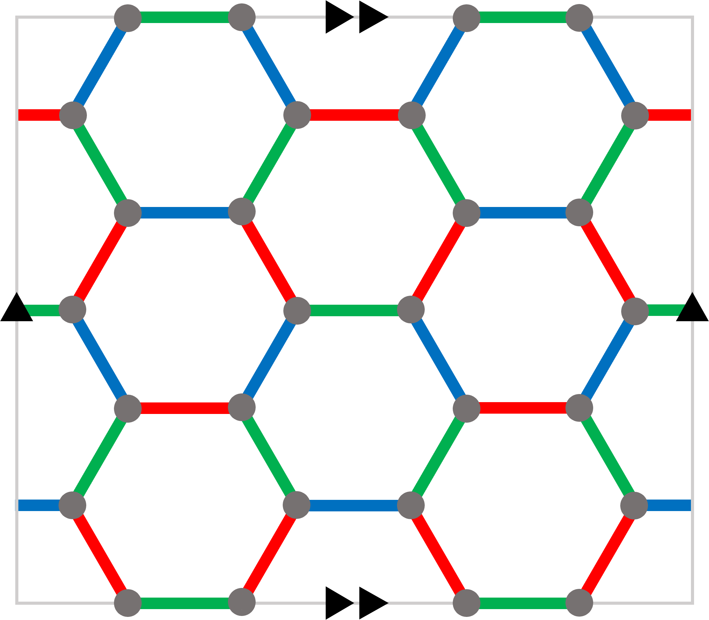
The first and arguably simplest example of Floquet codes is the honeycomb code [30, 31], which is defined on a hexagonal lattice with either periodic or open boundary conditions. The honeycomb code is realized by placing qubits on the vertices and measuring two-qubit Pauli operators associated with the edges in a specified sequence. Namely, Pauli , and operators are associated with red, blue and green edges, respectively, and are measured at a round .
One way to generalize the honeycomb code, which we refer to as a graph-based Floquet code, is by defining a QEC code based on a connected graph . We require that the vertices are three-valent and the edges are three-colorable, i.e., the edges split into three sets, , and no two different edges from are incident. We place qubits on the vertices and consider a measurement sequence of period three, where at a round we measure Pauli , and operators associated with edges in , and , respectively. The definition of graph-based Floquet codes is motivated by the possibility of having a native implementation of two-qubit Pauli measurements with erasure qubits; it also guarantees low qubit connectivity. We remark that our exhaustive search in Sec. V.1 finds the the smallest graph-based Floquet codes with distance two and four.
We can also consider a CSS version of graph-based Floquet codes, defined using a period-six measurement sequence; see Fig. 4 for an illustration of the CSS honeycomb code [44]. In what follows, we mostly focus on CSS Floquet codes, as they outperform the non-CSS counterparts; see Sec. IV.
So far, we have only discussed examples of Floquet codes without defining them. The foundational idea behind Floquet codes is that logical information is encoded in a dynamically evolving codespace. Consequently, a Floquet code can be defined by a sequence of measurements rounds , where each round consists of a set of commuting Pauli operators. From that perspective, Floquet codes are synonymous with a sequence of code switchings [45, 46, 47, 48, 49, 50] or dynamic automorphism codes [51]. Note that the operators from and may not commute for . In each round, the codespace is stabilized by an instantaneous stabilizer group (ISG) , which is an abelian subgroup of the Pauli group not containing . Measuring new operators in takes the previous codespace with ISG into a new codespace stabilized by . The new ISG is generated by along with all elements of that commute with the new measurements. We remark that stabilizer [52] and subsystem [53] codes correspond to Floquet codes with a measurement sequence of period one and two, respectively.
We can specify the code parameters of a Floquet code as follows. The ISG can be viewed as a stabilizer code with logical qubits. The sequence is nonincreasing, and therefore becomes a constant after some number of measurement rounds. We thus define the number of logical qubits of to be . The distance of should be defined as the circuit distance, i.e., the smallest number of spacetime faults that are undetectable yet cause a logical operator to be applied, which depends on the details of the syndrome extraction circuit. For simplicity, we instead consider the distance to be the minimum distance of the stabilizer code from any ISG (which provides an upper bound on the circuit distance) 222Note that the families of Floquet codes considered in Sec. IV have a growing circuit distance which is proportional to the distance. Such scaling of the circuit distance does not hold in general..
III.3 Implementation of erasure checks and Pauli measurements

Floquet codes with erasure qubits crucially rely on three operations, erasure checks, single-qubit gates on the computational subspace and projective measurements of Pauli operators. Since an erasure check is an extra operation that is not typically considered (on top of state preparation, entangling gates and Pauli measurements), it constitutes an additional hurdle to overcome. We mentioned that for erasure qubits via the dual-rail superconducting encoding erasure checks may, in principle, be realized by a projective measurement of the Pauli operator , but this is simplistic. Instead, there are efforts to design erasure checks in an optimized way, for instance, by symmetrically coupling a readout resonator to two transmons [18].
Surprisingly, for dual-rail qubits projective measurements of Pauli operators might be efficiently and swiftly realized using a single transmon almost without paying the price for the transmon’s low (compared to the dual-rail qubit’s) coherence and amplitude damping time . We propose to do so by incorporating the ideas from the cavity dual-rail architecture [19].

(a)
 (b)
(b)
 (c)
(c)
 (d)
(d)
 (e)
(e)
 (f)
(f)
Concretely, the parity measurement could be realized by coupling a single transmon (which will be used as an ancilla) to two dual-rail qubits and modulating the flux on the transmon parametrically in resonance with the gaps of the dual-rail qubits; see Fig. 5. Such a modulation realizes the following effective interaction , where is the interaction strength, is the ladder operator for the ancilla transmon and denotes Pauli operator on the computational subspace of the -th dual-rail qubit. Since the transmon is only coupled to , manipulating the ground and second excited states of the ancilla transmon allows for a robust parity measurement. This method is resilient not only to the phase noise of the ancilla transmon but also to the amplitude damping noise. Assuming that the coherence of the dual rail reaches a few milliseconds [23], the main source of noise in this scheme is expected to be measurement idling dephasing, which should be less than ; see Appendix C for details. By employing this scheme, we can directly implement the projective measurement of Pauli operators required for Floquet codes.
IV Numerical simulations for Floquet codes
(a)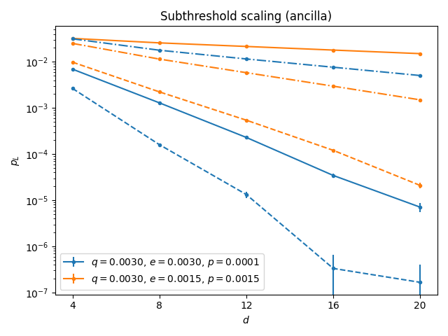
(b)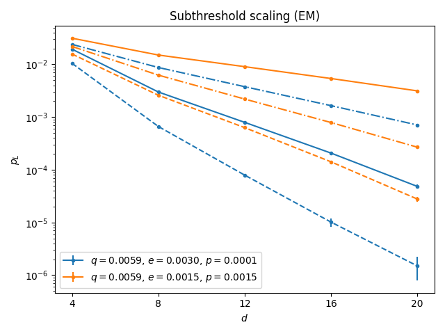
We now describe the results of our numerical simulations of Floquet codes with erasure qubits. Our simulations were performed using the second method of sampling described in Sec. II.3. After sampling erasure check detection events, we used the Python package Stim [55] to sample from the resulting stabilizer circuits. For each sample, Stim outputs detectors that are violated along with the final value of a given logical operator and decomposes noise into error mechanisms that set off at most two detectors. Thus, we decode using the method outlined in Sec. II.2 by inputting this decoding graph along with the samples to the minimum-weight perfect matching decoder PyMatching [56]. The decoder reports an error if after decoding, the value of the logical operator is different than when initialized. For a distance code, we calculate , the logical error rate per rounds. For more details of the simulation, see Appendix D.
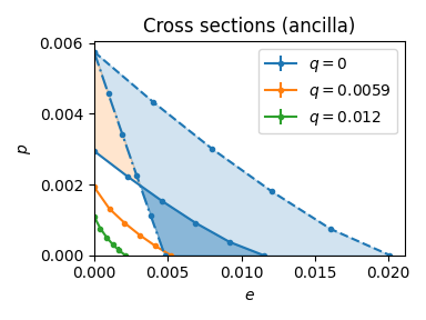
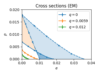
Our main numerical results are presented in Fig. 6. We simulate two ways of implementing the measurements of the CSS honeycomb code: (i) the ancilla scheme using an ancilla qubit and two-qubit entangling gates as depicted in Fig. 1 and (ii) the 2Q entangling measurement (EM) scheme as described Sec. III.3. In both scenarios we perform either erasure checks with reset or readout after each entangling operation. We probe the phase space to determine the threshold surface and find the correctable region where errors can be suppressed arbitrarily by increasing the code distance.
We remark that depending on the noise parameters it may be optimal to perform erasure checks less frequently than after every entangling operation. Although we have not simulated all possible erasure check schedules, we find an upper bound for their thresholds by simulating the scheme with ideal erasure checks and reset. In particular, the light blue and orange regions in Fig. 6(b)(e) represent potential gains of the correctable region that may be achieved by optimizing the erasure check schedules.
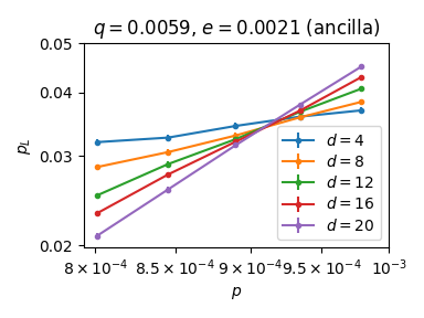
In Fig. 7, we show how the logical error rate is suppressed by increasing code distance for error rates below threshold in the ancilla and EM schemes. We choose , and to be in the correctable region for the erasure scheme from Fig. 6. These values are also comparable with the experimentally measured erasure and residual error rates of and per single-qubit gate, and the false positive and negative erasure detection rates of around [23].
(a)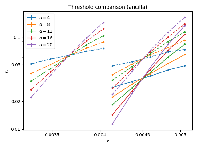
(b)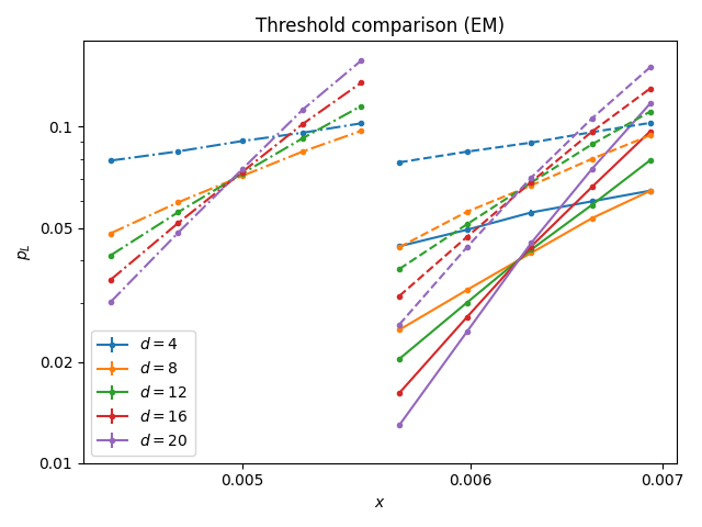
In Fig. 8, we present several optimizations where we find the threshold for the ancilla and EM schemes under erasure-biased noise characterized by a single parameter . We consider two layouts: (i) the standard embedding of the hexagonal lattice on a torus as in Fig. 4(a) and (ii) the qubit-efficient layout achieving the same distance by “twisting” the torus as in Fig. 9(f). This qubit-efficient layout, suggested in Refs. [57, 31], is the optimal layout on a torus for a given distance and uses 25% fewer qubits than the standard layout [58]. Although the logical error rate at the threshold is lower for the standard layout, at low physical error rates, where the scaling of is determined by the distance, it is preferential to use the compact layout as it achieves a higher distance for a given number of physical qubits. We also simulate the performance of the original honeycomb code with the compact layout and find that its threshold is lower than that of the CSS honeycomb code. This can be explained by the fact that the detectors are products of 6 measurement outcomes in the CSS honeycomb code compared to products of 12 measurement outcomes in the original honeycomb code. Therefore, the CSS version is more robust against measurement errors.
(a)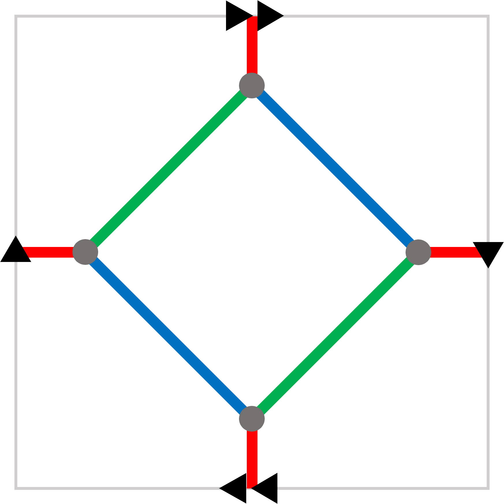 (b)
(b)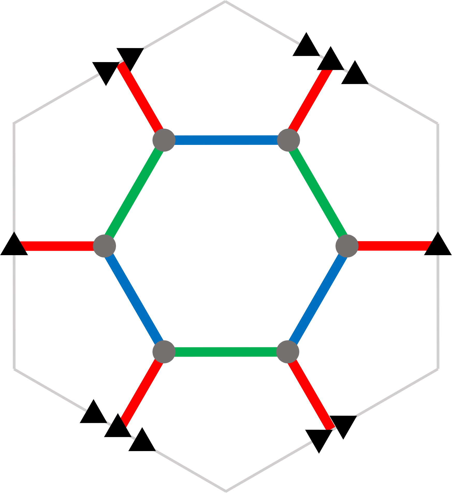 (c)
(c)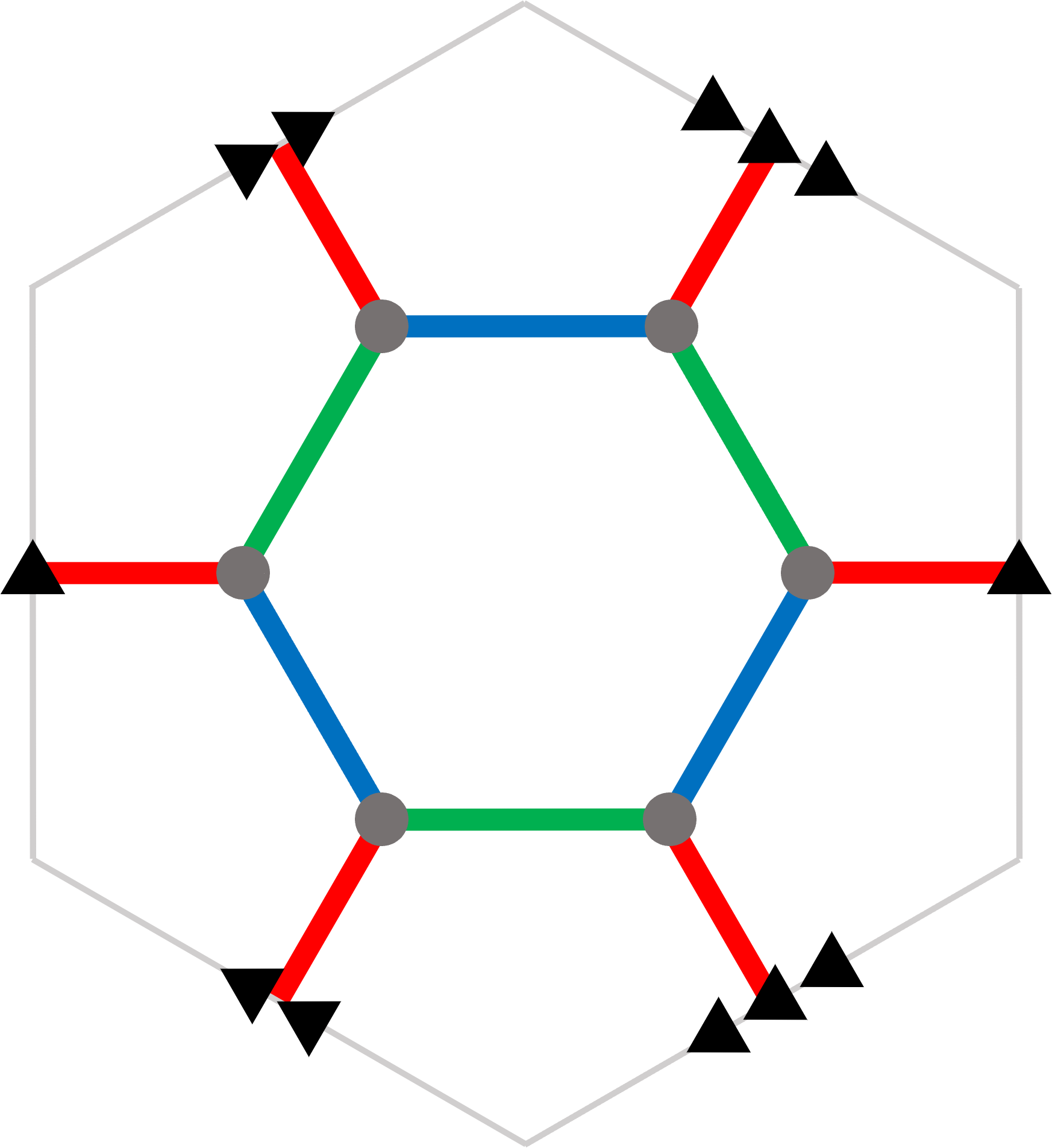
(d)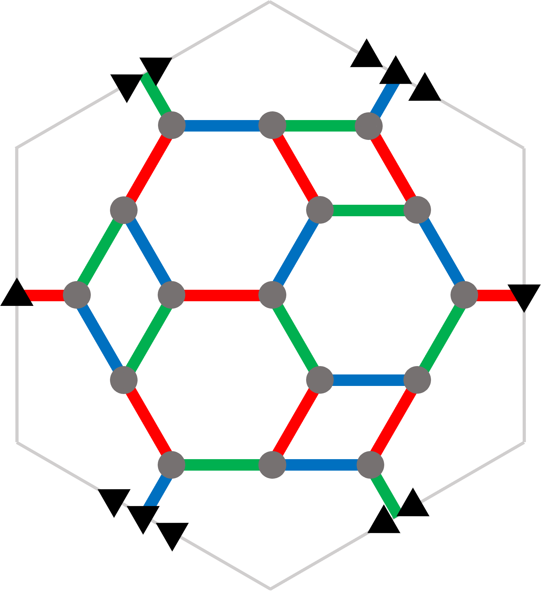 (e)
(e)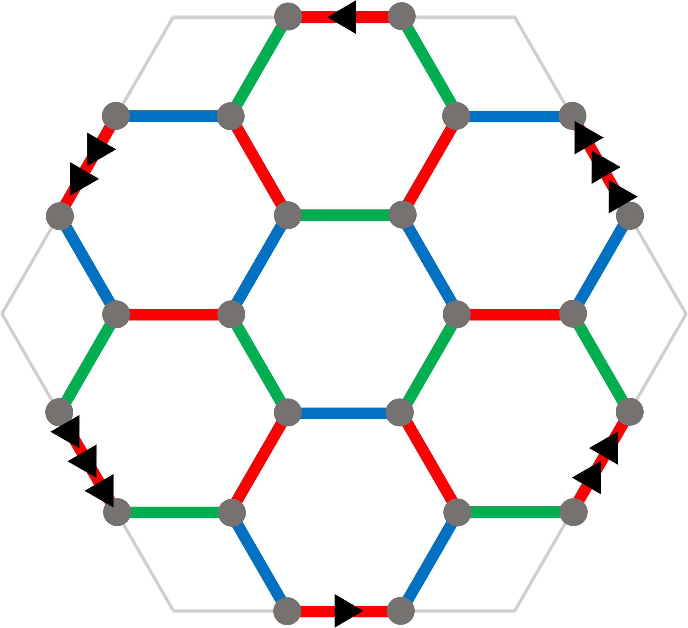 (f)
(f)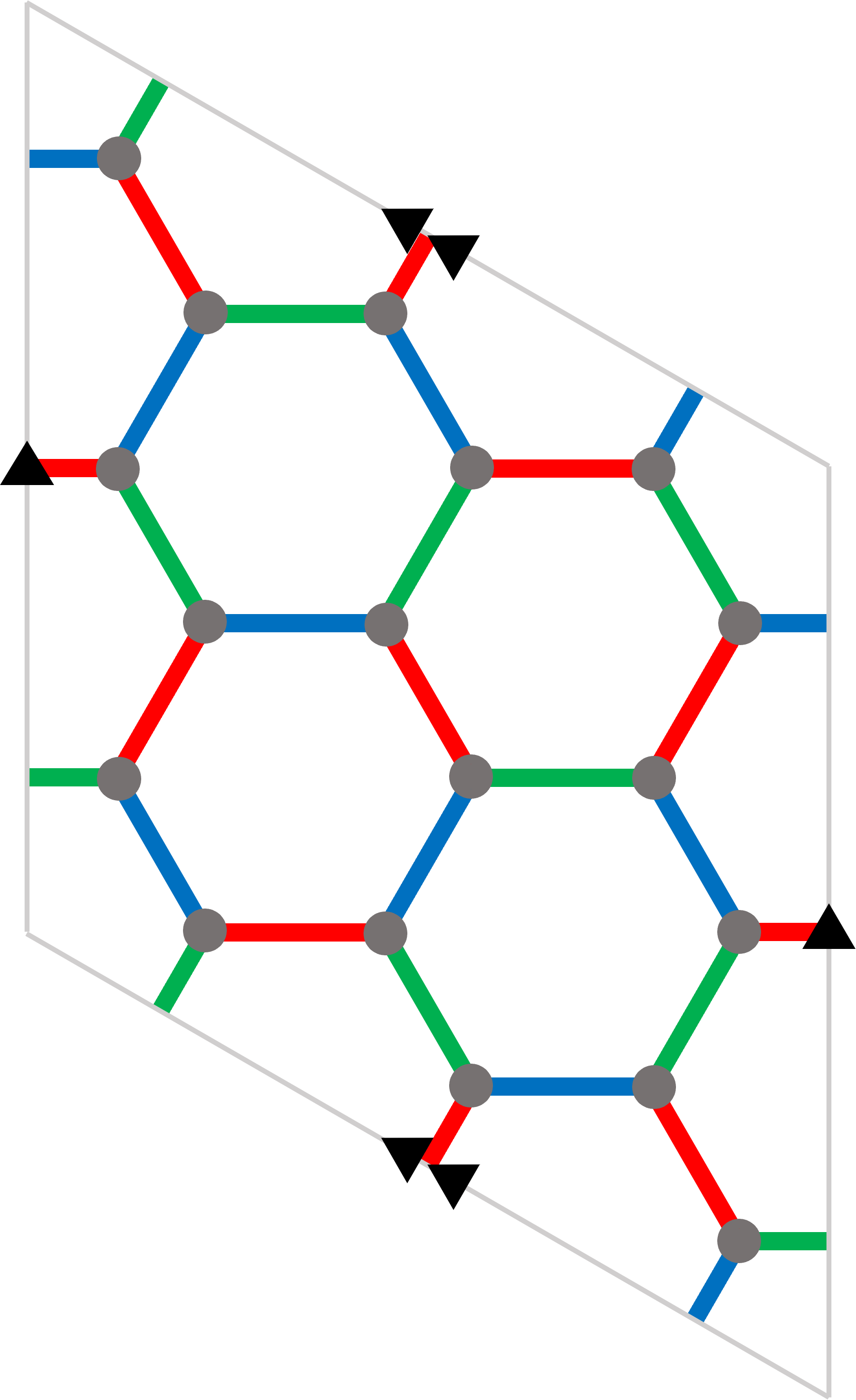
| code | ||||
|---|---|---|---|---|
| (a) | 4 | 1 | 2 | |
| (b) | 6 | 2 | 2 | |
| (c) | 6 | 2 | 2 | |
| (d) | 16 | 1 | 4 | |
| (e) | 18 | 1 | 4 | |
| (f) | 18 | 2 | 4 |
V Smallest Floquet codes
Having analyzed families of Floquet codes on the torus, one may ask what the smallest possible (graph-based) Floquet codes are. In this section, we find the previously unknown codes with distance two and four and analyze their performance in terms of the logical error rate. We also describe a connection between Floquet codes and two-manifolds.
V.1 Searching for smallest Floquet codes
Because we are considering erasures, distance-two codes may allow us to correct up to one erasure. The smallest 3-regular graphs are the complete graph , the complete bipartite graph , and the prism graph . Each of these graphs has exactly one 3-edge-coloring (up to isomorphism), so they define valid Floquet codes. The codes all have distance two, and they encode either one or two logical qubits. We depict them in Fig. 9(a)-(c). We remark that compared to the hyperbolic code defined on the Bolza surface [59], the codes defined on and have better encoding rates at the same distance.
For Floquet codes that can correct one unknown error, we consider distance-four codes. Previously, the smallest known Floquet code with distance four was the code using the twisted embedding of the hexagonal lattice on a torus [57, 31]; see Fig. 9(f). We ran an exhaustive search through all 3-edge-colorings of 3-regular graphs up to 18 vertices and found two additional distance-four codes with 16 and 18 qubits. These codes both encode one logical qubit; see Fig. 9(d)(e).
We also simulate the performance of the code, presenting the results for the ancilla and EM schemes in Fig. 10. To find the pseudothresholds, we compare the logical error rate of the code against an unprotected qubit that undergoes the same noise and is affected by four depolarizing channels, two with error rate and two with error rate , at every step. In the EM scheme, there are single error mechanisms that can corrupt two qubits along a logical operator, which halves the circuit distance compared to the distance of the stabilizer code of any ISG. This can be seen from the subthreshold scaling, as the the slopes of the solid and dashed lines are the same for low error rates. This phenomenon does not occur for the ancilla scheme.
(a)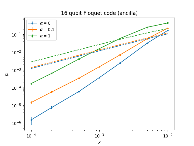
(b)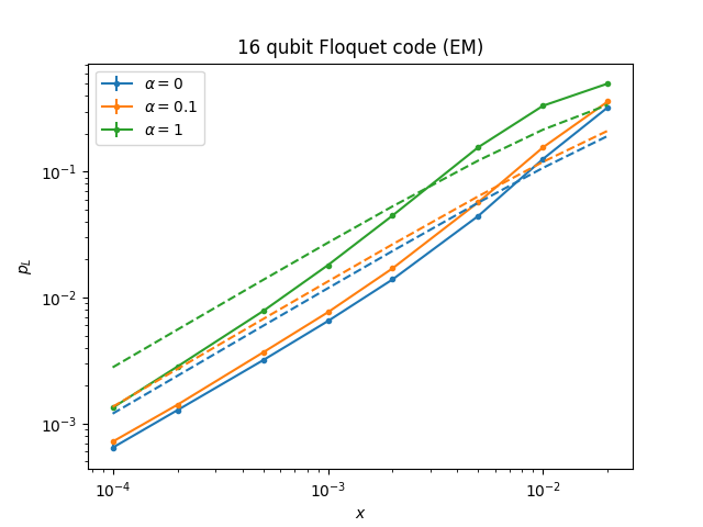
V.2 Interpretation through manifolds
It turns out that one can interpret any graph-based Floquet code as arising from a tessellation of some closed two-manifold (with the tessellation forming a two-dimensional color code lattice [60, 61]). By definition, a two-dimensional color code lattice is -valent and its faces are -colorable, i.e., faces are colored with three colors and any two neighboring faces sharing an edge have different colors. The following lemma guarantees the relation between Floquet codes and two-manifolds.
Lemma 2.
Any finite connected 3-regular graph with a -edge-coloring can be embedded in a closed two-manifold with -colorable faces, whose coloring is induced by the edge coloring.
Proof.
By removing all edges in , we obtain a disjoint union of cycles. Let denote the collection of these cycles. Consider filling in these cycles so that they are homeomorphic to disks. The boundaries of the disks are edges of the graph, and each edge in is part of exactly two cycles. By gluing disks together along an edge when they share the same edge in , we obtain a closed manifold on which has a natural embedding. The faces of are and their coloring is induced by the coloring of the edges of , i.e., any face in has color . Note that since each -colored edge is part of faces colored and , with all distinct, any two neighboring faces of have different colors (both distinct from ). ∎
The parameters of the Floquet code associated with the graph can be related to the -embedding of . Let us define the shrunk lattice of color to be the graph , where an edge connecting to in the original graph now connects the two -colored faces that and are on. The graph also has an embedding in , which is obtained from the embedding of by “shrinking” the -colored faces to a point and extending the -colored edges. Similarly to Ref. [30], we find that at every round of the evolution of the Floquet code, the ISG is equivalent to the toric code on the -embedding of . Thus, the number of encoded qubits is
| (7) | ||||
| (8) |
where is the first homology group of the two-manifold with coefficients and is the Euler characteristic of . Furthermore, the distance of the Floquet code at round is the smaller of twice the length of the shortest noncontractible cycle of and the length of the shortest noncontractible cycle in the dual graph . Since the dual graph is bipartite, the distance is even.
VI Discussion
In our article, we designed and optimized fault-tolerant quantum architectures based on erasure qubits. While our analysis has focused on Floquet codes, we also envision making use of other QEC codes, such as the surface code and quantum low-density parity-check codes [62]. The surface code, similarly to graph-based Floquet codes, can be realized with planar layouts of qubits and projective measurements of Pauli and operators between neighboring qubits [39, 63]; quantum low-density parity-check codes are generally incompatible with planar layouts, but, in principle, can be realized with, e.g., superconducting circuits [64] and neutral atoms [65]. Irrespective of the QEC codes used, we expect the corresponding quantum architectures to benefit from erasure qubits and significantly outperform standard approaches.
Our analysis and numerical simulations relied on certain simplifying assumptions, including the erasure-depolarization spread, noise rates that are uniform through the circuit, and frequent erasure checks followed by unconditional reset. However, similar analysis can be fine-tuned for specific architectures, making it more realistic and potentially further improving the performance of QEC protocols. For instance, if erasures spread to Pauli errors, then one may be able to design clever syndrome extraction circuits that suppress the error propagation. One may adjust the noise rate at each spacetime location depending on the execution time of quantum circuit operations; see Appendix B for an illustrative example. Also, one may choose to perform less frequent erasure checks (to reduce the time overhead associated with their implementation) and conditional reset operations (to reduce the effect of false negative erasure detections).
Lastly, our formalism for QEC protocols with erasure qubits and phrasing the corresponding decoding problem as the hypergraph matching problem constitute the first step toward systematic development and optimization of decoding algorithms. Such efforts, in turn, will further solidify the claim that erasure qubits are an attractive building block for fault-tolerant quantum architectures.
Acknowledgements.
We thank A. Grimsmo, A. Haim, C. Hann, J. Iverson and H. Levine for many inspiring discussions. We acknowledge C. Pattison for his help with finding small Floquet codes.Appendix A Formal description of QEC protocols with erasure qubits
We can make the discussion about QEC protocols with erasure qubits more precise. Formally, each wire represents an erasure qubit and it suffices to model it as a three-level system with an orthonormal basis , and , where the states and span the computational subspace and the state spans the erasure subspace . Let and , where , denote the projectors onto and , respectively. Similarly, we define and , where , to be the projectors onto the -eigenspaces of the Pauli and operators, respectively. We write to capture that the operator acts on .
In Sec. II.1 we assumed that none of the operations (i)-(vii) can create a superposition of states in the computational and erasure subspaces of erasure qubits. Given our assumption of the erasure-depolarization spread, i.e., an erasure causes full depolarization of other qubit that is involved in the same 2Q operation, we obtain that the operations (i)-(vii) have a block-diagonal structure and act on the Hilbert spaces associated with erasure qubits as follows.
-
(i)
1Q state preparation of a state in the computational subspace of the erasure qubit.
-
(ii)
1Q readout measures a Pauli operator, but if the state is erased, then it gives a random outcome, i.e., it performs the two-outcome positive operator-valued measure (POVM) with and .
-
(iii)
1Q gate acts on the computational subspace of the erasure qubit, i.e., .
-
(iv)
2Q gate acts on the computational subspace of the two erasure qubits and fully depolarizes the other qubit if one qubit is erased, i.e., it applies a quantum channel with Kraus operators for all .
-
(v)
1Q erasure check performs the two-outcome measurement with projectors and .
-
(vi)
1Q reset acts trivially on the computational subspace and reinitializes an erased state as the maximally mixed state in the computational subspace, i.e., it applies a quantum channel with Kraus operators , and .
-
(vii)
2Q projective measurement measures a Pauli operator, but if either qubit is erased, then it gives a random outcome and fully depolarizes the other qubit, i.e., it performs the two-outcome POVM with and followed by an application of a quantum channel with Kraus operators for all .
Appendix B Examples of the edge-weight calculation and erasure rate adjustment
(a)
(b)
We present an example of how to decode erasures by converting a segment of an erasure circuit into a stabilizer circuit. Consider the segment in Fig. 11(a), where each erasure location has probability and the erasure check outcome is flipped with probability . The erasure detection event has distribution
| (9) | ||||
| (10) |
Conditioned on , the probabilities that the qubit was first erased at or are respectively
| (11) |
if , and
| (12) |
if . If the qubit was first erased at , it would depolarize the second qubit after the entangling gate. Furthermore, the qubit itself would become maximally mixed after the reset operation. Thus, both qubits become fully depolarized. If the qubit was first erased at , only that qubit would become depolarized from the reset. By the proof of Lemma 1, the segment is equivalent to the stabilizer circuit in Fig. 11(b) with error probabilities
| (13) |
To adjust erasure rates at different spacetime locations depending on the execution time of quantum circuit operations (and thereby making numerical simulations more realistic) we can use the following simple heuristic. Let be the erasure time (which for the erasure qubit via the dual-rail encoding corresponds to the amplitude damping time ). Let be an erasure location in between two consecutive quantum operations and with the execution time and , respectively. We can then set the erasure rate associated with to be
| (14) |
where are appropriately chosen. In particular, in the middle of the segment we may set ; if or correspond to one of the endpoint of , then we set or to be 1. We also remark that adjusting and for erasure locations adjacent to erasure checks allows us to effectively adjust the false positive and negative erasure detection rates.
Appendix C Parity measurement of two dual-rail qubits
Here, we outline our scheme for parity measurement of two dual-rail qubits that utilizes a single transmon for measurement. The proposed scheme is based on Fig. 5. The dual-rail qubits are encoded in transmons T1, T2 and T3, T4, respectively, while the interaction is generated by the coupler T5 within the T2, T5, T3 system.
Each dual-rail qubit consists of two tunable transmons, brought to resonance as in Refs. [18, 23], while the single tunable transmon T5 facilitates the parity measurement. The reason why we can employ such a hybrid construction combining high-coherence dual-rail qubits and a low-coherence transmon is that most of the noise on the ancilla transmon commutes with the interaction, and thereby does not propagate in leading order to the dual-rail qubits as in Ref. [66]. Part of the noise that does propagate is addressed by the dual-rail qubit’s built-in decoupling mechanism.
Furthermore, since this construction is similar in nature to the cavity setup [19], the interaction can be made much faster as it is not limited by the Purcell effect, which is the main limitation of the rate for high-coherence cavities in a hybrid construction.
The interaction is generated by the second order coupling between T5 and T1 and T5 and T3 in the following way. Starting with the Hamiltonian
where is the frequency of the transmon T, is the nonlinearity, is the capacitive coupling between two transmons of the -th dual-rail qubit and is the capacitive coupling between the ancilla transmon T5 and either T2 or T3.
In the limit of large detunings, , , when , and the coupling between T5 and the rest of the system reduces to
| (16) |
when This Hamiltonian becomes
| (17) |
Here, and are Pauli operators of the -th dual-rail qubit defined in the standard way for the computational basis states and , where , with and denoting the transmon’s ground and first excited states, respectively (note the change of basis compared to the main text). In principle the interaction terms are off resonance and thus could be neglected unless is modulated at the dual-rail qubit frequency .
The coupling term could be modulated by a parametric drive of the detuning resulting in . Thus, by modulating the gap detuning for one of the dual-rail qubits, it is possible to realize an effective Hamiltonian or . Moreover, by modulating at both frequencies it is possible to realize a Hamiltonian . By adding local terms this Hamiltonian could be written as , where denotes the transmon’s second excited state. This is exactly what is needed to implement the gate proposed in Ref. [19]. Here, however, we only aim to use this term to implement a parity measurement, simplifying the scheme and resulting in higher fidelity.
C.1 Parity measurement scheme
We propose to conduct the parity measurement via the ground state and the second excited state manifold, enabling us to detect amplitude damping of the transmon by measuring the first excited state . The protocol starts with the state
| (18) |
where denotes the computational basis state of the dual-rail qubit. By setting the total time so that the unitary propagates the state to
| (19) |
which, followed by measuring the operator , realizes the parity measurement. The main advantage of this scheme is that amplitude damping is heralded, and the phase noise of the transmon does not propagate to the dual-rail qubits because the coupling term commutes with the noise term. Thus, the transmon’s phase noise only affects the measurement error, benefiting from a large threshold, as discussed in Ref. [66]. This property of the measurement scheme allows for the utilization of a low-coherence single transmon and does not necessitate the use of a dual-rail qubit as an ancilla or a coupler, which would have slowed down the protocol considerably.

The parity measurement itself is slower by a factor of 2 than the regular term between two transmons and taking into account that the gate should be realized twice, once for each dual rail, the gate could be achieved at around . The dephasing due to the dual-rail qubit would be of the order of for the Markovian case and down to the level for the non Markovian one, where the estimation of the coherence time is based on results in Ref. [23]. Thus, the main source of dephasing would be the erasure measurements. The erasure measurement takes a similar amount of time as a regular measurement, which could be performed in less than [67] or even below [68]. The measurement idiling dephasing will be the main source of noise in this scheme and should be less than assuming that the coherence of the dual-rail qubit would reach a few miliseconds [23].
The low transmon’s coherence will only limit the measurement fidelity to the level of , where is the parity measurement time, which is not a real limitation as measurement fidelities are already limited to that level due to other reasons.
The gate speed will be limited by the off-resonant error terms which will cause leakage at the end of the gate. These transitions are shown in Fig. 12. As these transitions are detuned by the error terms are approximately [69]. Assuming we target a fidelity of around the gate time should be of the order of .
(a)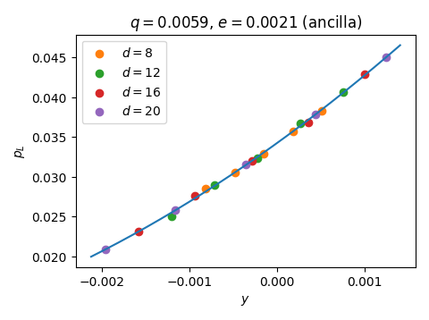
(b)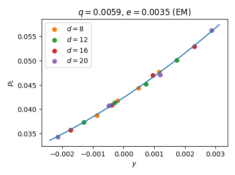
(a)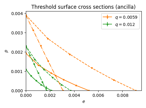
(b)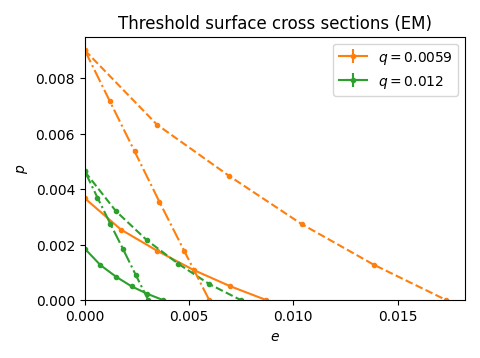
Appendix D Details of numerical simulations
We present more details on how the simulations were performed. For a given circuit, the state is initialized as the eigenstate of a chosen logical operator, and an error is reported if the logical operator is decoded to the wrong value at the end of the simulation 333Because Floquet codes encode two logical qubits, the word error rate is four times the values presented if we assume independent and failure probabilities. The thresholds will remain the same.. Because we are interested in threshold values, we assume perfect initialization and a noiseless final measurement. We run the simulation for noisy measurement rounds for to obtain , and then report the normalized error rate per rounds calculated via . The logical error rate is calculated as the average over at least 1000 circuit realizations (from a given pattern of erasure check detection events), where each circuit realization is sampled 200 times.
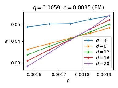
The threshold surfaces in Fig. 6 are obtained by sweeping an error parameter (usually , but sometimes or for points where ) in the neighborhood of a suspected threshold point in the phase space. The threshold value is estimated by fitting the universal scaling ansatz for critical points of phase transitions [71, 72]. That is, around the threshold, we assume the form
| (20) |
for the scaled variable
| (21) |
where is the logical error rate, is the swept error variable, and are fitting parameters; see Fig. 13 for example calculations. In Fig. 14, we present additional cross sections of the threshold surfaces from Fig. 6.
References
- Shor [1995] P. W. Shor, Scheme for reducing decoherence in quantum computer memory, Physical Review A 52, R2493 (1995).
- Steane [1996] A. M. Steane, Error correcting codes in quantum theory, Physical Review Letters 77, 793 (1996).
- Shor [1996] P. Shor, Fault-tolerant quantum computation, in Proceedings of 37th Conference on Foundations of Computer Science (IEEE Comput. Soc. Press, 1996) pp. 56–65.
- Cochrane et al. [1999] P. T. Cochrane, G. J. Milburn, and W. J. Munro, Macroscopically distinct quantum-superposition states as a bosonic code for amplitude damping, Physical Review A 59, 2631 (1999).
- Mirrahimi et al. [2014] M. Mirrahimi, Z. Leghtas, V. V. Albert, S. Touzard, R. J. Schoelkopf, L. Jiang, and M. H. Devoret, Dynamically protected cat-qubits: a new paradigm for universal quantum computation, New Journal of Physics 16, 045014 (2014).
- Ofek et al. [2016] N. Ofek, A. Petrenko, R. Heeres, P. Reinhold, Z. Leghtas, B. Vlastakis, Y. Liu, L. Frunzio, S. Girvin, L. Jiang, et al., Extending the lifetime of a quantum bit with error correction in superconducting circuits, Nature 536, 441 (2016).
- Puri et al. [2019] S. Puri, A. Grimm, P. Campagne-Ibarcq, A. Eickbusch, K. Noh, G. Roberts, L. Jiang, M. Mirrahimi, M. H. Devoret, and S. M. Girvin, Stabilized cat in a driven nonlinear cavity: a fault-tolerant error syndrome detector, Physical Review X 9, 041009 (2019).
- Guillaud and Mirrahimi [2019] J. Guillaud and M. Mirrahimi, Repetition cat qubits for fault-tolerant quantum computation, Physical Review X 9, 041053 (2019).
- Tuckett et al. [2018] D. K. Tuckett, S. D. Bartlett, and S. T. Flammia, Ultrahigh error threshold for surface codes with biased noise, Physical Review Letters 120, 050505 (2018).
- Tuckett et al. [2019] D. K. Tuckett, A. S. Darmawan, C. T. Chubb, S. Bravyi, S. D. Bartlett, and S. T. Flammia, Tailoring surface codes for highly biased noise, Physical Review X 9, 041031 (2019).
- Tuckett et al. [2020] D. K. Tuckett, S. D. Bartlett, S. T. Flammia, and B. J. Brown, Fault-tolerant thresholds for the surface code in excess of 5% under biased noise, Physical Review Letters 124, 130501 (2020).
- Bonilla Ataides et al. [2021] J. P. Bonilla Ataides, D. K. Tuckett, S. D. Bartlett, S. T. Flammia, and B. J. Brown, The xzzx surface code, Nature Communications 12, 1 (2021).
- Dua et al. [2022] A. Dua, A. Kubica, L. Jiang, S. T. Flammia, and M. J. Gullans, Clifford-deformed surface codes, arXiv:2201.07802 (2022).
- Xu et al. [2023a] Q. Xu, N. Mannucci, A. Seif, A. Kubica, S. T. Flammia, and L. Jiang, Tailored xzzx codes for biased noise, Physical Review Research 5, 013035 (2023a).
- Higgott et al. [2023] O. Higgott, T. C. Bohdanowicz, A. Kubica, S. T. Flammia, and E. T. Campbell, Improved decoding of circuit noise and fragile boundaries of tailored surface codes, Physical Review X 13, 031007 (2023).
- Wu et al. [2022] Y. Wu, S. Kolkowitz, S. Puri, and J. D. Thompson, Erasure conversion for fault-tolerant quantum computing in alkaline earth rydberg atom arrays, Nature Communications 13, 4657 (2022).
- Kang et al. [2023] M. Kang, W. C. Campbell, and K. R. Brown, Quantum error correction with metastable states of trapped ions using erasure conversion, PRX Quantum 4, 020358 (2023).
- Kubica et al. [2023] A. Kubica, A. Haim, Y. Vaknin, H. Levine, F. Brandão, and A. Retzker, Erasure qubits: Overcoming the limit in superconducting circuits, Physical Review X 13, 041022 (2023).
- Teoh et al. [2023] J. D. Teoh, P. Winkel, H. K. Babla, B. J. Chapman, J. Claes, S. J. de Graaf, J. W. O. Garmon, W. D. Kalfus, Y. Lu, A. Maiti, K. Sahay, N. Thakur, T. Tsunoda, S. H. Xue, L. Frunzio, S. M. Girvin, S. Puri, and R. J. Schoelkopf, Dual-rail encoding with superconducting cavities, Proceedings of the National Academy of Sciences 120, e2221736120 (2023).
- Ma et al. [2023] S. Ma, G. Liu, P. Peng, B. Zhang, S. Jandura, J. Claes, A. P. Burgers, G. Pupillo, S. Puri, and J. D. Thompson, High-fidelity gates and mid-circuit erasure conversion in an atomic qubit, Nature 622, 279–284 (2023).
- Scholl et al. [2023] P. Scholl, A. L. Shaw, R. B.-S. Tsai, R. Finkelstein, J. Choi, and M. Endres, Erasure conversion in a high-fidelity rydberg quantum simulator, Nature 622, 273–278 (2023).
- Chou et al. [2023] K. S. Chou, T. Shemma, H. McCarrick, T.-C. Chien, J. D. Teoh, P. Winkel, A. Anderson, J. Chen, J. Curtis, and S. J. e. a. de Graaf, Demonstrating a superconducting dual-rail cavity qubit with erasure-detected logical measurements, arXiv:2307.03169 (2023).
- Levine et al. [2023] H. Levine, A. Haim, J. S. C. Hung, N. Alidoust, M. Kalaee, L. DeLorenzo, E. A. Wollack, P. A. Arriola, A. Khalajhedayati, R. Sanil, Y. Vaknin, A. Kubica, A. A. Clerk, D. Hover, F. Brandão, A. Retzker, and O. Painter, Demonstrating a long-coherence dual-rail erasure qubit using tunable transmons, arXiv:2307.08737 (2023).
- Koottandavida et al. [2023] A. Koottandavida, I. Tsioutsios, A. Kargioti, C. R. Smith, V. R. Joshi, W. Dai, J. D. Teoh, J. C. Curtis, L. Frunzio, R. J. Schoelkopf, and M. H. Devoret, Erasure detection of a dual-rail qubit encoded in a double-post superconducting cavity, arXiv:2311.04423 (2023).
- Grassl et al. [1997] M. Grassl, T. Beth, and T. Pellizzari, Codes for the quantum erasure channel, Physical Review A 56, 33 (1997).
- Stace et al. [2009] T. M. Stace, S. D. Barrett, and A. C. Doherty, Thresholds for topological codes in the presence of loss, Physical Review Letters 102, 200501 (2009).
- Delfosse and Nickerson [2021] N. Delfosse and N. H. Nickerson, Almost-linear time decoding algorithm for topological codes, Quantum 5, 595 (2021).
- Sahay et al. [2023] K. Sahay, J. Jin, J. Claes, J. D. Thompson, and S. Puri, High-threshold codes for neutral-atom qubits with biased erasure errors, Physical Review X 13, 041013 (2023).
- Dennis et al. [2002] E. Dennis, A. Kitaev, A. Landahl, and J. Preskill, Topological quantum memory, Journal of Mathematical Physics 43, 4452 (2002).
- Hastings and Haah [2021] M. B. Hastings and J. Haah, Dynamically generated logical qubits, Quantum 5, 564 (2021).
- Haah and Hastings [2022] J. Haah and M. B. Hastings, Boundaries for the honeycomb code, Quantum 6, 693 (2022).
- Duan et al. [2010] R. Duan, M. Grassl, Z. Ji, and B. Zeng, Multi-error-correcting amplitude damping codes, in 2010 IEEE International Symposium on Information Theory (2010) pp. 2672–2676.
- Gottesman [1998] D. Gottesman, The heisenberg representation of quantum computers, in Proc. XXII International Colloquium on Group Theoretical Methods in Physics, 1998 (1998) pp. 32–43.
- Aaronson and Gottesman [2004] S. Aaronson and D. Gottesman, Improved simulation of stabilizer circuits, Physical Review A 70, 052328 (2004).
- Aliferis and Terhal [2007] P. Aliferis and B. M. Terhal, Fault-tolerant quantum computation for local leakage faults, Quantum Information and Computation 7, 139 (2007).
- Varbanov et al. [2020] B. M. Varbanov, F. Battistel, B. M. Tarasinski, V. P. Ostroukh, T. E. O’Brien, L. DiCarlo, and B. M. Terhal, Leakage detection for a transmon-based surface code, npj Quantum Information 6, 102 (2020).
- Miao et al. [2023] K. C. Miao, M. McEwen, J. Atalaya, D. Kafri, L. P. Pryadko, A. Bengtsson, A. Opremcak, K. J. Satzinger, Z. Chen, P. V. Klimov, C. Quintana, R. Acharya, K. Anderson, M. Ansmann, F. Arute, K. Arya, A. Asfaw, J. C. Bardin, A. Bourassa, J. Bovaird, L. Brill, B. B. Buckley, D. A. Buell, T. Burger, B. Burkett, N. Bushnell, J. Campero, B. Chiaro, R. Collins, P. Conner, A. L. Crook, B. Curtin, D. M. Debroy, S. Demura, A. Dunsworth, C. Erickson, R. Fatemi, V. S. Ferreira, L. F. Burgos, E. Forati, A. G. Fowler, B. Foxen, G. Garcia, W. Giang, C. Gidney, M. Giustina, R. Gosula, A. G. Dau, J. A. Gross, M. C. Hamilton, S. D. Harrington, P. Heu, J. Hilton, M. R. Hoffmann, S. Hong, T. Huang, A. Huff, J. Iveland, E. Jeffrey, Z. Jiang, C. Jones, J. Kelly, S. Kim, F. Kostritsa, J. M. Kreikebaum, D. Landhuis, P. Laptev, L. Laws, K. Lee, B. J. Lester, A. T. Lill, W. Liu, A. Locharla, E. Lucero, S. Martin, A. Megrant, X. Mi, S. Montazeri, A. Morvan, O. Naaman, M. Neeley, C. Neill, A. Nersisyan, M. Newman, J. H. Ng, A. Nguyen, M. Nguyen, R. Potter, C. Rocque, P. Roushan, K. Sankaragomathi, H. F. Schurkus, C. Schuster, M. J. Shearn, A. Shorter, N. Shutty, V. Shvarts, J. Skruzny, W. C. Smith, G. Sterling, M. Szalay, D. Thor, A. Torres, T. White, B. W. K. Woo, Z. J. Yao, P. Yeh, J. Yoo, G. Young, A. Zalcman, N. Zhu, N. Zobrist, H. Neven, V. Smelyanskiy, A. Petukhov, A. N. Korotkov, D. Sank, and Y. Chen, Overcoming leakage in quantum error correction, Nature Physics 19, 1780–1786 (2023).
- Note [1] For brevity, we also refer to state preparation and readout as reset operations.
- Chao et al. [2020] R. Chao, M. E. Beverland, N. Delfosse, and J. Haah, Optimization of the surface code design for Majorana-based qubits, Quantum 4, 352 (2020).
- Delfosse et al. [2023] N. Delfosse, A. Paetznick, J. Haah, and M. B. Hastings, Splitting decoders for correcting hypergraph faults (2023), arXiv:2309.15354 [quant-ph] .
- Edmonds [1965] J. Edmonds, Paths, trees, and flowers, Canadian Journal of Mathematics 17, 449–467 (1965).
- Yan et al. [2018] F. Yan, D. Campbell, P. Krantz, M. Kjaergaard, D. Kim, J. L. Yoder, D. Hover, A. Sears, A. J. Kerman, T. P. Orlando, S. Gustavsson, and W. D. Oliver, Distinguishing coherent and thermal photon noise in a circuit quantum electrodynamical system, Physical Review Letters 120, 260504 (2018).
- Burnett et al. [2019] J. J. Burnett, A. Bengtsson, M. Scigliuzzo, D. Niepce, M. Kudra, P. Delsing, and J. Bylander, Decoherence benchmarking of superconducting qubits, npj Quantum Information 5, 1 (2019).
- Davydova et al. [2023a] M. Davydova, N. Tantivasadakarn, and S. Balasubramanian, Floquet codes without parent subsystem codes, PRX Quantum 4, 020341 (2023a).
- Bombin and Martin-Delgado [2009] H. Bombin and M. A. Martin-Delgado, Quantum measurements and gates by code deformation, Journal of Physics A: Mathematical and Theoretical 42, 095302 (2009).
- Horsman et al. [2012] D. Horsman, A. G. Fowler, S. Devitt, and R. V. Meter, Surface code quantum computing by lattice surgery, New Journal of Physics 14, 123011 (2012).
- Paetznick and Reichardt [2013] A. Paetznick and B. W. Reichardt, Universal fault-tolerant quantum computation with only transversal gates and error correction, Physical Review Letters 111, 090505 (2013).
- Bombín [2015] H. Bombín, Gauge color codes: optimal transversal gates and gauge fixing in topological stabilizer codes, New Journal of Physics 17, 083002 (2015).
- Kubica and Beverland [2015] A. Kubica and M. E. Beverland, Universal transversal gates with color codes: A simplified approach, Physical Review A 91, 032330 (2015).
- Vuillot et al. [2019] C. Vuillot, L. Lao, B. Criger, C. García Almudéver, K. Bertels, and B. M. Terhal, Code deformation and lattice surgery are gauge fixing, New Journal of Physics 21, 033028 (2019).
- Davydova et al. [2023b] M. Davydova, N. Tantivasadakarn, S. Balasubramanian, and D. Aasen, Quantum computation from dynamic automorphism codes, arXiv:2307.10353 (2023b).
- Gottesman [1997] D. E. Gottesman, Stabilizer Codes and Quantum Error Correction, Ph.D. thesis (1997).
- Poulin [2005] D. Poulin, Stabilizer formalism for operator quantum error correction, Physical Review Letters 95, 230504 (2005).
- Note [2] Note that the families of Floquet codes considered in Sec. IV have a growing circuit distance which is proportional to the distance. Such scaling of the circuit distance does not hold in general.
- Gidney [2021] C. Gidney, Stim: a fast stabilizer circuit simulator, Quantum 5, 497 (2021).
- Higgott and Gidney [2023] O. Higgott and C. Gidney, Sparse blossom: correcting a million errors per core second with minimum-weight matching, arXiv:2303.15933 (2023).
- Gidney et al. [2021] C. Gidney, M. Newman, A. Fowler, and M. Broughton, A Fault-Tolerant Honeycomb Memory, Quantum 5, 605 (2021).
- Bombin and Martin-Delgado [2007] H. Bombin and M. A. Martin-Delgado, Optimal resources for topological two-dimensional stabilizer codes: Comparative study, Physical Review A 76, 012305 (2007).
- Higgott and Breuckmann [2023] O. Higgott and N. P. Breuckmann, Constructions and performance of hyperbolic and semi-hyperbolic floquet codes, arXiv:2308.03750 (2023).
- Bombin and Martin-Delgado [2006] H. Bombin and M. A. Martin-Delgado, Topological quantum distillation, Physical Review Letters 97, 180501 (2006).
- Kubica [2018] A. M. Kubica, The ABCs of the Color Code: A Study of Topological Quantum Codes as Toy Models for Fault-Tolerant Quantum Computation and Quantum Phases Of Matter, Ph.D. thesis (2018).
- Breuckmann and Eberhardt [2021] N. P. Breuckmann and J. N. Eberhardt, Quantum low-density parity-check codes, PRX Quantum 2, 040101 (2021).
- Gidney [2023] C. Gidney, A Pair Measurement Surface Code on Pentagons, Quantum 7, 1156 (2023).
- Bravyi et al. [2023] S. Bravyi, A. W. Cross, J. M. Gambetta, D. Maslov, P. Rall, and T. J. Yoder, High-threshold and low-overhead fault-tolerant quantum memory, arXiv:2308.07915 (2023).
- Xu et al. [2023b] Q. Xu, J. P. B. Ataides, C. A. Pattison, N. Raveendran, D. Bluvstein, J. Wurtz, B. Vasic, M. D. Lukin, L. Jiang, and H. Zhou, Constant-overhead fault-tolerant quantum computation with reconfigurable atom arrays, arXiv:2308.08648 (2023b).
- Zuk et al. [2023] I. Zuk, D. Cohen, A. V. Gorshkov, and A. Retzker, Robust gates with spin-locked superconducting qubits, arXiv:2306.09149 (2023).
- Heinsoo et al. [2018] J. Heinsoo, C. K. Andersen, A. Remm, S. Krinner, T. Walter, Y. Salathé, S. Gasparinetti, J.-C. Besse, A. Potočnik, A. Wallraff, et al., Rapid high-fidelity multiplexed readout of superconducting qubits, Physical Review Applied 10, 034040 (2018).
- Sunada et al. [2023] Y. Sunada, K. Yuki, Z. Wang, T. Miyamura, J. Ilves, K. Matsuura, P. A. Spring, S. Tamate, S. Kono, and Y. Nakamura, Photon-noise-tolerant dispersive readout of a superconducting qubit using a nonlinear purcell filter, arXiv:2309.04315 (2023).
- Boradjiev and Vitanov [2013] I. I. Boradjiev and N. V. Vitanov, Control of qubits by shaped pulses of finite duration, Physical Review A 88, 013402 (2013).
- Note [3] Because Floquet codes encode two logical qubits, the word error rate is four times the values presented if we assume independent and failure probabilities. The thresholds will remain the same.
- Wang et al. [2003] C. Wang, J. Harrington, and J. Preskill, Confinement-higgs transition in a disordered gauge theory and the accuracy threshold for quantum memory, Annals of Physics 303, 31–58 (2003).
- Harrington [2004] J. W. Harrington, Analysis of Quantum Error-Correcting Codes: Symplectic Lattice Codes and Toric Codes, Ph.D. thesis (2004).