A Superconducting Single-Atom Phonon Laser
C.A. Potts1,†, W.J.M. Franse1, V.A.S.V. Bittencourt2, A. Metelmann2,3,4 and G.A. Steele
1Kavli Institute of Nanoscience, Delft University of Technology, PO Box 5046, 2600 GA Delft, The Netherlands
2ISIS (UMR 7006), Université de Strasbourg, 67000 Strasbourg, France
3Institute for Theory of Condensed Matter, Karlsruhe Institute of Technology, 76131 Karlsruhe, Germany
4Institute for Quantum Materials and Technology, Karlsruhe Institute of Technology, 76344 Eggenstein-Leopoldshafen, Germany
†Email: c.a.potts@tudelft.nl
∗Email: g.a.steele@tudelft.nl
The development of quantum acoustics has enabled the cooling of mechanical objects to their quantum ground state, generation of mechanical Fock-states, and Schrödinger cat states. Such demonstrations have made mechanical resonators attractive candidates for quantum information processing, metrology, and tests of quantum gravity theories. Here, we experimentally demonstrate a direct quantum-acoustic equivalent of a single-atom laser. A single superconducting qubit coupled to a high-overtone bulk acoustic resonator is used to drive the onset of phonon lasing. We observe the absence of a sharp lower lasing threshold and characteristic upper lasing threshold, unique predictions of single-atom lasing. Lasing of an object with an unprecedented g mass represents a new regime of laser physics and provides a foundation for integrating phonon lasers with on-chip devices.
INTRODUCTION
The development of the laser in the early 1960s has proven to be one of the most important breakthroughs in modern physics. The laser found its niche in the advancement of atomic physics, resulting in numerous groundbreaking discoveries such as spectroscopic measurements of atomic species Schawlow (1982, 1978), laser cooling of atoms Phillips and Metcalf (1982); Phillips (1998), and the realization of Bose-Einstein condensation Anderson et al. (1995); Davis et al. (1995). Beyond this, lasers are indispensable tools in areas like gravitational wave detection Abbott et al. (2016), biology Chaurasiya et al. (2016), chemistry McCreery (2005), and even in medicine Khalkhal et al. (2019).
The advancements enabled by optical lasers have motivated the development of lasing states of mechanical vibrations — phonon lasersMahboob et al. (2013); Vahala et al. (2009); Pettit et al. (2019); Kuang et al. (2023); Behrle et al. (2023). Coherent sources of phonons are interesting for coupling mechanical strain to electron spins and color centers Shandilya et al. (2021), coherent driving of magnetic spin-waves Hatanaka et al. (2022, 2023), improving the resolution of force sensors Cui et al. (2021), fundamental tests of quantum mechanics Behrle et al. (2023), and nonlinear phononics Kuang et al. (2023). However, to date, phonon lasing has been realized with the center of mass motion of levitated microspheres or ions Vahala et al. (2009); Pettit et al. (2019); Kuang et al. (2023); Behrle et al. (2023), limiting the integrability of these coherent phonon sources. In other examples of phonon lasers in literature, the lasing state is the result of dispersive or dissipative optomechanical coupling Shandilya et al. (2021); Cui et al. (2021); Zhang et al. (2018); Grudinin et al. (2010); Potts et al. (2021); Parsa et al. (2023) — without population inversion — which are well described as mechanical parametric instabilities Kippenberg and Vahala (2008) or as optically driven pulsed semiconductor heterostructures Bron and Grill (1978); Wallentowitz et al. (1996); Camps et al. (2001).
This article demonstrates, for the first time, the direct phononic analog of a single-atom optical laser McKeever et al. (2003); Dubin et al. (2010); An et al. (1994). A single two-level artificial atom driven coherently into population inversion couples to a bulk on-chip phonon mode generating a lasing state. The lasing is observed through a dramatically extended ringdown of the artificial atom excited by the phonon laser and demonstrates the nearly threshold-free nature of single-atom lasers. We also observe a unique predicted feature of single-atom lasers, an upper lasing threshold Dubin et al. (2010); Mu and Savage (1992); Ashhab et al. (2009). Our experimental observations agree with the theoretical and numerical models we use to characterize the system. Moreover, the bulk nature of the phonon mode may allow the future integration of color centers or quantum dots, enabling strain engineering or coherent mechanical driving. The coherent state generated via phonon lasing may be used as an efficient displacement pulse for generating large displacement Schrodinger cat states Bild et al. (2023). Generating larger cat states may allow for future tests of exotic theories of gravitationally induced quantum decoherence Gely and Steele (2021); Schrinski et al. (2023). Future implementations of this architecture may even enable phonon spectroscopy of vibrational transitions of complex molecules and crystal structures Wybourne and Wigmore (1988) or even biological samples Romero-Isart et al. (2011).
EXPERIMENTAL SETUP
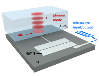
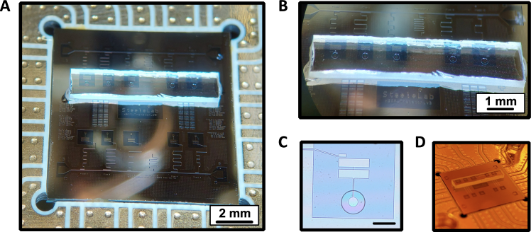
Our device comprises a flip-chip BAR architecture with two bonded device chips Bild et al. (2023); von Lüpke et al. (2023, 2022); Chu et al. (2018, 2017). We have implemented a fully on-chip integration, which can multiplex different devices on a single silicon chip Välimaa et al. (2022); Crump, Välimaa, and Sillanpää (2023). A single feedline is coupled to the individual superconducting fixed-frequency transmon qubits. The transmon qubits were fabricated from niobium-titanium nitride for the bulk structures with aluminum Josephson junctions. A sapphire substrate, m thick, was positioned above each transmon qubit and bonded to the silicon substrate, see Fig. 1. The sapphire chip supports a set of longitudinal high-overtone bulk acoustic wave resonances (HBARs) separated by a free spectral range of MHz. The electric field of a transmon qubit coherently couples to the strain of an HBAR acoustic mode via a disk of piezoelectric aluminum nitride patterned on the sapphire. Each qubit on the chip is nearly resonant with an HBAR mode of interest; in such a way, a pair of qubit-HBAR modes behaves like a single atom coupled to a phononic mode. The qubits were read out via on-chip microwave resonators using standard circuit quantum electrodynamics techniques Krantz et al. (2019); Reed et al. (2010). Our device is similar to those used in previous work generating mechanical Schrödinger cat states Bild et al. (2023) and for circuit quantum acoustodynamics Chu et al. (2017).
Using the dispersive shift of a coupled linear readout resonator, we can measure the steady-state qubit population Krantz et al. (2019). In the limit where the qubit and the readout resonator are far detuned in frequency, the qubit-cavity Hamiltonian can be written as:
| (1) |
where are the readout and qubit frequency, is the photon annihilation (creation) operator, is the qubit population operator, and is the qubit-state dependent frequency shift of the readout resonator. The coupling between the phonon and the qubit is described by a resonant Jaynes-Cummings interaction Chu et al. (2017), given by the Hamiltonian:
| (2) |
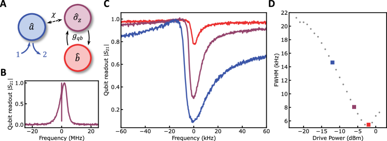
where is the coupling rate between the qubit and the phonon mode, are the qubit raising and lowering operators, and is the phonon annihilation (creation) operator; see Fig. 2(a).
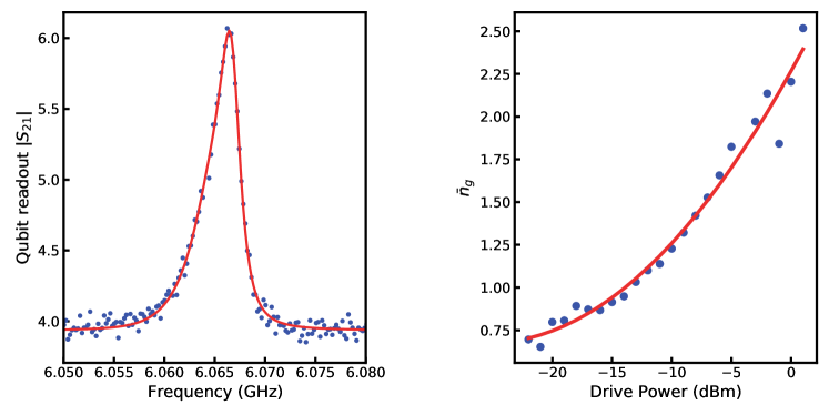
The qubit’s state was measured by applying a weak probe tone on resonance with the readout resonator and monitoring the transmitted signal as a second tone was swept near the qubit frequency. The transmission spectrum at the readout frequency directly maps to the qubit occupation ; see Fig. 2(b). The asymmetry of the qubit spectrum is due to the finite photon population within the readout resonator Gambetta et al. (2006); Lachance-Quirion et al. (2017) and is well described by our theoretical model. Moreover, the narrow transparency window within the qubit spectrum results from the coherent swaps between the qubit and the phonon mode. In this work, the qubit and the phonon frequency were detuned by approximately MHz. See the discussion in the supplementary text for full details. However, as will be discussed below, coherent Rabi oscillations between the qubit and phonon modes do not provide a clear picture of the dynamics at high drive powers.
PHONON LASING
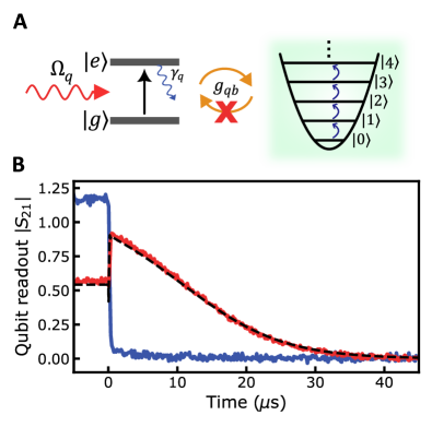
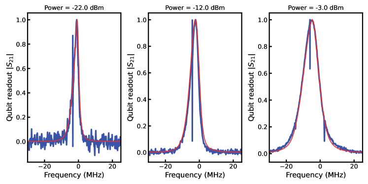
Three distinct features can be observed within the two-tone spectrum when increasing the qubit drive power. First, the qubit linewidth is power-broadened Schuster et al. (2005); Gambetta et al. (2006). Large qubit drive powers increase the qubit decay rate due to increased stimulated emission. Less intuitive is the gradual disappearance and narrowing of the phonon-induced transparency window; see Fig. 2(c). The total linewidth of the transparency window is proportional to the phonon linewidth and demonstrates an inverse dependence on the drive power; see Fig. 2(d). This dependence is reminiscent of linewidth narrowing described by the Schawlow-Townes equation and is a known property of lasing states Gordon, Zeiger, and Townes (1955). These features can be understood by considering the schematic shown in Fig. 3(a).
As described before, the qubit and phonon modes coherently exchange excitations at the lowest qubit drive powers, which can be understood as a bosonic beam-splitter-type interaction. However, as the qubit drive power increases, the qubit is excited by the drive and coherently exchanges an excitation with the phonon mode. But before the phonon mode can exchange the excitation back to the qubit, the external drive re-excites the qubit. The qubit excitation can again be coherently swapped into the phonon mode, causing the phonon mode to climb the Fock state ladder. In the steady state, this process results in a phonon mode described by a large coherent state; i.e. the phonon mode starts lasing. A strong qubit drive allows the phonon mode to accept energy from the qubit but prevents the qubit from accepting energy from the phonon mode; see Fig. 3(a). This process also provides an intuitive understanding of the reduced visibility of the transparency window. As the drive power increases, the phonon mode no longer exchanges energy with the qubit; therefore, probing the qubit provides no information about the phonon mode.
Finally, at the highest qubit drive powers, the qubit linewidth has been increased such that the rapid decay of the qubit population results in a self-quenching of phonon lasing Mu and Savage (1992). Counterintuitively this results in an upper lasing threshold above which the phonon mode is no longer lasing. Instead, the qubit incoherently exchanges excitations with the phonon mode, reducing the phonon amplitude. It should also be noted that the phonon mode statistics are no longer described as a coherent state above the upper threshold. This process has been described previously in the context of single-atom photon lasers McKeever et al. (2003) and is captured by our theoretical description; see the supplementary text.
GATED TWO-TONE SPECTROSCOPY
Directly probing the phonon mode is not possible in the current experimental configuration since the readout is performed via the two-level system and not through a propagating photon mode Kuang et al. (2023); Behrle et al. (2023). Direct measurements of the Rabi oscillations between the qubit and phonon state could be possible and have been previously used to measure Fock-states in BAR devices Chu et al. (2018). However, this data would provide little clarity due to the short lifetime of our qubit and the multiplicity of simultaneous Rabi oscillation frequencies given by , which scale with the phonon mode amplitude .Chu et al. (2018) Instead, we rely on the mismatch between the decay rate of the phonon mode s and that of the qubit. Using gated two-tone ringdown measurements, we can distinguish pure qubit decay from qubit decay driven by a highly excited phonon state. If the phonon mode is highly excited—in the absence of an external drive—the coherent Jaynes-Cummings interaction will continually drive the qubit, resulting in an extended relaxation of the qubit population compared to its intrinsic relaxation rate.
Gated two-tone measurements were performed, driving the qubit until the system reached its steady state; at this point, the drive was switched off using an RF switch. During the entire sequence, the frequency of the readout resonator is monitored using a vector network analyzer, averaging multiple traces triggered synchronously with the RF switch; see the supplementary text for more information. This measures the expectation value of the qubit population as a function of time, with a temporal resolution of ns.
First, the drive power was set near the peak of the lasing amplitude and was detuned kHz above the HBAR resonance. The gated two-tone measurement was performed, and the blue data points in Fig. 3(b) show the resulting time domain measurement and a ringdown on the order of ns. This corresponds to the intrinsic decay of the transmon qubit. A second measurement was performed at the same drive power, but the drive was tuned resonant with the HBAR. A ringdown on the order of s is observed for this configuration, represented by the red data points in Fig. 3(b). The extended ringdown confirms the highly excited phonon amplitude of the mechanical state. When the qubit drive is switched off, the phonon mode can exchange excitations with the qubit, continually re-exciting the qubit until the phonon mode has decayed back to its ground state. Moreover, near the peak phonon amplitude, in contrast to a thermal state, the coherent state generated by the lasing results in a qubit ringdown that is not exponential; instead, the qubit ringdown is approximately linear. This feature is captured by our numerical model, the dashed curve in Fig. 3(b). Moreover, our model also captures the ring-up of the qubit and is described within the supplementary information.
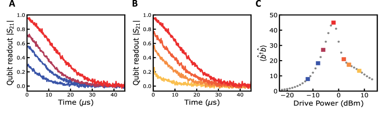
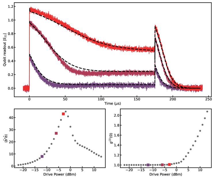
We can estimate the phonon population from our numerical model by fitting the spectroscopic and ringdown data. The estimated phonon population is shown in Fig. 4(c) as a function of qubit drive power. At a power of -2.0 dBm, the phonon population is nearly maximized, corresponding to the ringdown in Fig. 4(a,b), and the upper lasing threshold is clearly visible as the phonon population rapidly reduces with increasing drive power. The upper threshold is experimentally confirmed by performing a set of gated ringdown measurements at a series of qubit drive powers. With increasing qubit drive power, the individual ringdown traces grow in amplitude and increase in duration, corresponding to the increasing phonon population, as shown in Fig. 4(a). At a drive power of -2.0 dBm, the phonon ringdown obtains its peak amplitude and duration, indicating a peak in the phonon population, shown in Fig. 4, which agrees with the minimum in the transparency window linewidth, shown in Fig. 2(b). Further increasing the qubit drive power beyond -2.0 dBm the qubit ringdown decreases in amplitude and duration, a direct indication of the self-quenching nature of the single-atom phonon laser, see Fig. 4(b). The upper threshold is a defining signature of a single-atom laser Mu and Savage (1992), and the agreement between the gated qubit ringdown and our numerical simulations indicates that we have indeed demonstrated a single-atom phonon laser.
CONCLUSION
This article demonstrates the experimental realization of a phononic analog to the optical single-atom laser. Our experiment consists of a superconducting single-atom, realized using a transmon style qubit coupled resonantly to an HBAR mode. When driving on resonance with the HBAR mode, the intrinsic non-linearity of the qubit-phonon coupling generates a highly excited phonon state — the phonon laser. A key feature of this experiment is the population inversion of a two-level atom rather than the parametric instability driving phonon excitations. Moreover, the phonon mode is confined in a bulk longitudinal mode within a sapphire substrate. The bulk nature may allow the phonon laser’s integration with additional on-chip architectures, such as color centers or quantum dots.
Our results have demonstrated the successful generation of a coherent phonon laser, and we have further demonstrated a counterintuitive feature of phonon lasers, an upper instead of a lower lasing threshold Ashhab et al. (2009). The size of the coherent lasing state achieved in this work was limited by both the qubit and phonon linewidth. However, the primary limiting factor was the phonon linewidth. Decreasing the decay rates will reduce the upper lasing threshold power and increase the peak lasing amplitude. Future studies could include a linear probe of the phonon mode to probe the phonon statistics. Such an on-chip phonon laser promises to provide a highly coherent source of phonons, which have applications from sensing to quantum information processing.
ACKNOWLEDGMENTS
The authors thank Enrique Sahagun for the device rendering Sci . W.J.M.F and G.A.S. acknowledge support through the QUAKE project, project number 680.92.18.04, of the research programme Natuurkunde Vrije Programma’s of the Dutch Research Council (NWO). C.A.P. acknowledges the support of the Natural Sciences and Engineering Research Council of Canada (NSERC). A.M and V.A.S.V.B. acknowledge financial support from the Contrat Triennal 2021-2023 Strasbourg Capitale Europeenne.
Authors contributions C.A.P. performed experiments, theoretical modelling, conceptualization, and wrote the manuscript. W.J.M.F. fabricated the device and performed experiments. V.A.S.V.B. performed theoretical modelling. A.M. provided supervision and funding acquisition. G.A.S. provided supervision, conceptualization and funding acquisition. Competing interests: The authors declare no competing interests.
Data and materials availability All data, analysis code, and measurement software are available in the manuscript or the supplementary material or are available at Zenodo .
Supplementary Information
I Materials and Methods
I.1 Device Fabrication
Qubit Chip
The device fabrication starts with a 10x10mm chip 525 m thick high resistivity silicon deposited with nm of niobium-titanium nitride (NbTiN). The NbTiN film was deposited by the Dutch Institute for Space Research (SRON) following the process described in Thoen et al. (2016). A layer of photoresist (AR-P 6200.18, 4000 rpm) was patterned, exposed (EBPG 5200, 315 m/cm2) and developed (Pentylacetate, O-xylene, IPA) to form the bulk circuitry (transmon islands and coplanar waveguides). The exposed NbTiN was removed using a reactive ion etch (Sentech Etchlab 200, 13.5 sccm + 5 sccm , 55 W, 10 bar) followed by an in-situ oxygen descum (50 sccm ,100 W, 10 bar). After stripping the photoresist, a bilayer resist stack (MAA 8.5% EL6, 2000 rpm and PMMA A6 950k, 1500 rpm; baked for three and five minutes at 180 C∘, respectively) was used for patterning the Josephson junctions (190 nm width). The junctions were patterned using e-beam lithography. The bilayer was developed using Cold : IPA (1:3) and cleaned afterwards with IPA. After cleaning the exposed silicon surface with an oxygen descum (200 sccm, 100 W) and acid clean (BoE(7:1):, 1:1), the chip was placed in an aluminum evaporator (Plassys MEB550). Double-angle shadow evaporation with intermediate in-situ oxidation was used to create Manhattan-style junctions. The aluminum was evaporated at a angle relative to the substrate at a rotational angle of and . The top and bottom electrodes were 35 and 75 nm thick, respectively. After the first evaporation step, the aluminum was oxidized to create the Al tunnel barriers. Following the second evaporation step, a second oxidation step was performed to cap the junctions with a passivation layer. After performing liftoff in NMP, the qubit chip was finished.
HBAR Chip
The HBAR chip started with double-side polished four-inch sapphire wafers with a 1 m thick film of c-axis oriented AlN (Kyma technologies, AT.U.100.1000.B). The wafer was diced into 10x10mm chips for easier processing. A photoresist layer (AR-N 4450.10, 6000 rpm) was used to pattern circular regions, m in diameter, to mask the AlN. A reactive ion etch in an Oxford 100 was performed to create AlN disks ( at 4.0/26.0/10.0 sccm, 350 W ICP power, 70 W RF power). Following the reactive ion etch, the AlN layer has the proper shape but not the correct thickness. After stripping the photoresist, the chip was placed again inside the etcher to etch the AlN to nm thickness.
Flip Chip
Once fabrication on both chips was done, the HBAR chip was diced into 8x2 mm chips. The HBAR chip was then flipped on top of the qubit chip with the AlN layer facing down. Using probe needles, the AlN disks were aligned with the transmon antennas. Once aligned, the probe needles held down the chips in position while a tapered fiber was used to apply two-component epoxy (Loctite EA 3430) on the sides of the top chip; see Fig. S1. After the epoxy was cured, the chip was wire-bonded and installed onto the baseplate of the dilution refrigerator.
I.2 Measurement Setup
Two-Tone Spectroscopy
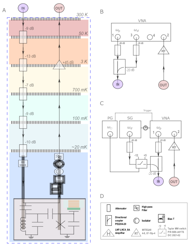
All measurements were performed within a dilution refrigerator operating at a base temperature mK. A schematic of the dilution refrigerator setup and the room-temperature electronics are shown in Fig. S2. The device was mounted on the mixing chamber plate of the dilution refrigerator and connected to a set of coaxial cables. The device was measured in transmission, with the resonators coupled in a ’notch’-style geometry. The output signals went into a cryogenic HEMT (High Electron Mobility Transistor) amplifier (LNF-LNC4-8A), followed by additional room-temperature amplification (Miteq AFS3-04000800-07-10P-4). The input line was attenuated at each stage to reduce the electron temperature and the thermal radiation at the input port of our device. A total of 48 dB of attenuation was used, plus any additional attenuation from the coaxial cables.
The two-tone spectroscopy was measured using a vector network analyzer (VNA). Port one and port three were combined using a directional coupler, with port three attached to the -20 dB coupling port. Port one was set into zero span mode and output a constant signal tuned on resonance with the Stark shifted readout resonator, , with an output power of -25 dBm. An additional 60 dB of attenuation was added to this signal before the directional coupler. Port 3 was used as a spectroscopic tone and was swept near the qubit frequency, and its power was varied throughout the experiment and had an additional 40 dB of attenuation. The combined signals from port one and there were then connected to the input line of the dilution refrigerator.
The output from the dilution refrigerator was directly connected to port 4 of the VNA set in zero span mode at the readout resonator frequency . Two-tone spectroscopy was performed by slowly sweeping the qubit drive tone, ensuring the system has reached its steady state and monitoring the readout resonators transmission spectrum .
Gated Two-Tone Spectroscopy
For the gated two-tone measurement, port one of the VNA was set up just as in the two-tone measurement. An external signal generator generated the qubit drive tone. The qubit drive tone was passed through an RF switch before being combined with the readout tone using a directional coupler. The RF switch was triggered using a pulse generator at a 3 kHz repetition rate. The signal generator was set to a 22.5% duty cycle, so the qubit drive was off for 75 s per trace. The VNA was synchronously triggered by the signal generator allowing for 65536 trace averages to be performed (maximum setting). Each trace averaged measurement was repeated 75 additional times to improve the signal-to-noise ratio further.
II Theory
II.1 System Hamiltonian and Master Equation
The system consists of a microwave cavity coupled to a transmon qubit which in turn is coupled to an HBAR phonon mode. The transmon qubit can be considered, up to a good approximation, to be a two-level system. The readout cavity is driven two with coherent tones: one at a frequency , which we call the probe tone, and one at a frequency , which we call the drive tone. The experiment measures the coupling between the qubit and the phonon mode via two-tone spectroscopy performed via the cavity. The procedure consists of considering the cavity detuned from the qubit, setting the probe tone at the (shifted) cavity frequency and varying the drive tone close to the qubit Lamb-shifted frequency. The transmission of the cavity carries information about the qubit correlations . The phonon mode has a frequency close to the qubit frequency.
We model the system with the Hamiltonian
| (S1) | ||||
where are the annihilation (creation) operators for the readout cavity with frequency , are the annihilation (creation) operators for the HBAR mode with frequency , is the qubit population operator with qubit frequency . The couplings are defined by the rates between the qubit and the readout cavity and between the qubit and the HBAR mode, where we assume that . Finally, the two drives are described by the amplitude with frequencies . The system is operated in the cavity-qubit dispersive regime . We then consider the standard Schrieffer-Wolff transformation up to the first order in . Defining , the transformed Hamiltonian reads
| (S2) | ||||
The Lamb-shifted qubit frequency is . Given the system’s parameters, we will discard the qubit-mediated beam-splitter term . Furthermore, in the two-tone spectroscopic setup, we can retain only the probe term for the cavity and only the drive term for the qubit. With such approximations, we have
| (S3) | ||||
where we have defined . It is convenient to move to a frame co-rotating with the pump and the probe frequencies, for which the Hamiltonian in Eq. (S3) reads
| (S4) | ||||
where , , and . We have defined the readout cavity detuning to included the Lamb shift, however, this decision is arbitrary. The density matrix of the system has dynamics described by the master equation
| (S5) |
Here is the cavity decay, is the phonon decay, is the qubit population decay, and is the qubit dephasing. We have assumed zero temperature and ignored small corrections to the dissipator due to the Schrieffer-Wolff transformation.
II.2 Qubit Two-Tone Spectroscopy
Following the arguments presented in Gambetta et al. (2006), ignoring the qubit-phonon coupling, in the dispersive regime, is directly related to the qubit population . By recording the phase of the readout resonator, one can then obtain the qubit absorption spectrum
| (S6) |
where indicates that the expectation value is taken in the steady state.
It was shown that for a qubit-cavity system, the qubit absorption spectrum is given by Gambetta et al. (2006)
| (S7) |
with
| (S8) | ||||
In the above equations, and are the frequency and linewidth of the qubit with the readout resonator in the state , respectively. The intrinsic qubit linewidth, with the readout resonator in its ground state, is given by , where is the longitudinal relaxation rate, and is the pure dephasing rate. The qubit frequency is ac Stark shifted by from its intrinsic value . We have also assumed that the readout drive is on resonance with the readout resonator, i.e. , and the readout resonator has a full-width half-maximum linewidth . In the limit and with , the components have non-Lorentzian lineshapes and can even be negative. The sum of these individual components can result in an asymmetry of the qubit spectrum, as seen in Fig. S3(a).
We perform spectroscopy of the qubit by monitoring the transmission coefficient of the readout resonator as a function of the qubit drive frequency . The probe tone was fixed at the Stark-shifted readout resonator frequency with the qubit in its ground state GHz, such that and held at a constant power dBm, set at room temperature. The probe line has a total of 108 dB of attenuation, ensuring the average number of photons in the probe mode on average is much less than one.
To fit the measured spectrum, we use the expression,
| (S9) |
where is a conversation factor between and and is a constant offset of the spectrum. The value of the Fock basis was truncated to , and the linewidth of the readout resonator was independently determined and fixed; see Table. 1. The fitting parameters include the intrinsic qubit frequency , the power broadened qubit linewidth , where is the qubit drive power, the qubit dispersive shift , the probe mode occupancy with the qubit in its ground state , and conversion factor , and the constant offset .
An example spectrum and its fit are shown in Fig. S3(a). First, the value of the dispersive shift was determined to be MHz, which agreed with our designed value. This value was then fixed, and the data was fit for all qubit drive powers to determine the remaining values. We found that the ground state readout photon population depended on the qubit drive power. This is likely due to the heating of the silicon substrate because the qubit drive tone was applied via the readout resonator. The value of is shown in Fig. S3(b). The zero power qubit linewidth was also extracted by extrapolating the measured power-broadened qubit linewidth to zero power and was determined to be MHz, which agrees with our limit determined using a time-domain measurement with ns. The comparison between our spectroscopy and time domain measurements indicates that our qubit decay is dominated by decoherence, and therefore we have ignored intrinsic dephasing in our model since qubit dephasing will be dominated by power-induced dephasing induced by the qubit drive tone.
II.3 Master Equation Simulations
Qubit Spectroscopy
We simulate the dynamics of the master equation Eq. S5 using the Python package Qutip Johansson, Nation, and Nori (2012). We first compare the measured qubit spectrum without the phonon mode to the Qutip steady-state simulations. To begin, we must consider the non-zero photon population of the readout resonator. The finite population results in an asymmetry in the qubit spectrum, as well as additional measurement-induced dephasing. To include the finite readout population in our simulation, the readout drive was set such that the average population . This ensured that for each qubit drive power, the readout resonator had the appropriate number of steady-state photons.
To account for qubit power-broadening, the qubit drive power in the simulation had to be calibrated. As stated above, , where , is the external coupling rate to the readout resonator, and is the drive power in Watts at the coupling port of the readout resonator. Therefore, the drive coefficient can be written in the form
| (S10) |
where calibrates the room-temperature power to the corresponding value of accounting for all losses and multiplicative factors. The value of was determined by matching the simulation to the power-broadened qubit spectrum at multiple qubit drive powers. A set of qubit spectra is shown in Fig. S4 where it can be seen that the master equation simulation is in excellent agreement capturing the qubit asymmetry at low power, and the power-broadened qubit spectrum at higher drive powers. It should be noted the measured transmission signal is proportional to the qubit population only if the appropriate signal quadrature is measured. Here this was determined by calculating the rotation angle that minimized the signal in the out-of-phase quadrature. To confirm, we compared our single-trace two-tone data with a direct measurement of the readout resonator frequency at several qubit drive powers. At the highest drive powers, we observed a slight deviation resulting from signal mixing into the out-of-phase quadrature. However, this was at the drive powers above the self-quenching threshold and resulted in a slight mismatch between our experimental and simulated two-tone traces.
Gated Ringdown
Following the calibration of the qubit spectrum, the phonon mode was included in the master equation simulation. The value of the coupling rate and the phonon linewidth were determined by performing a fit to the time domain gated two-tone measurements. The fit was determined by fitting both the ringdown (as shown in the main text) and also the ring-up of the qubit. The best-fit values were then compared at multiple drive powers; see Fig. S5(a). We extracted a value of the qubit phonon coupling of kHz and a phonon linewidth of kHz. From this set of simulations, the steady-state phonon population and phonon statistics can be estimated for multiple drive powers. We observe a good agreement between the numerical simulation and the ring-up data and an excellent agreement between the ringdown data for all powers. Deviations in the ring-up simulations likely result from higher-order nonlinearities we are not considering in our model.
The master equation simulations directly calculate the time dynamics of , this value has been scaled by the same constant factor for all powers to give a direct comparison to our two-tone measurement. Since we expect the variation in the transmission coefficient measured in the two-tone measurement to be proportional to , see Eq. S3 and Ref. Gambetta et al. (2006). From our simulation, we calculate the phonon population and second-order correlation function for multiple drive powers, shown in Fig. S5(b,c). For low drive powers, the phonon statistics are described by a coherent state, , as expected for a laser. However, as discussed in the main text, single-atom lasers exhibit self-quenching above a given upper-threshold power. This can be seen in both the phonon population, as a rapid decrease in the populations, and in the phonon statistics as for drive powers above the self-quenching threshold.
| Parameter | Symbol |
|---|---|
| Microwave mode frequency | GHz |
| Microwave mode decay | MHz |
| Phonon mode frequency | GHz |
| Phonon mode decay | kHz |
| Qubit frequency | GHz |
| Qubit energy relaxation rate | MHz |
| Qubit phase relaxation rate | MHz |
| Qubit-phonon coupling | kHz |
| Dispersive cavity-qubit coupling | MHz |
| Lamb-shifted qubit frequency | |
| Qubit drive frequency | , varied around |
| Cavity probe frequency | , set at the Stark-shifted cavity frequency |
References
- Schawlow (1982) A. L. Schawlow, “Spectroscopy in a new light,” Reviews of Modern Physics 54, 697 (1982).
- Schawlow (1978) A. L. Schawlow, “Laser spectroscopy of atoms and molecules: The abundance of new laser techniques is making possible a variety of spectroscopic experiments.” Science 202, 141–147 (1978).
- Phillips and Metcalf (1982) W. D. Phillips and H. Metcalf, “Laser deceleration of an atomic beam,” Physical Review Letters 48, 596 (1982).
- Phillips (1998) W. D. Phillips, “Nobel lecture: Laser cooling and trapping of neutral atoms,” Reviews of Modern Physics 70, 721 (1998).
- Anderson et al. (1995) M. H. Anderson, J. R. Ensher, M. R. Matthews, C. E. Wieman, and E. A. Cornell, “Observation of bose-einstein condensation in a dilute atomic vapor,” science 269, 198–201 (1995).
- Davis et al. (1995) K. B. Davis, M.-O. Mewes, M. R. Andrews, N. J. van Druten, D. S. Durfee, D. Kurn, and W. Ketterle, “Bose-einstein condensation in a gas of sodium atoms,” Physical review letters 75, 3969 (1995).
- Abbott et al. (2016) B. P. Abbott, R. Abbott, T. Abbott, M. Abernathy, F. Acernese, K. Ackley, C. Adams, T. Adams, P. Addesso, R. Adhikari, et al., “Observation of gravitational waves from a binary black hole merger,” Physical review letters 116, 061102 (2016).
- Chaurasiya et al. (2016) S. Chaurasiya, P. Hew, P. Crosley, D. Sharon, K. Potts, K. Agopsowicz, M. Long, C. Shi, and M. Hitt, “Breast cancer gene therapy using an adenovirus encoding human il-2 under control of mammaglobin promoter/enhancer sequences,” Cancer Gene Therapy 23, 178–187 (2016).
- McCreery (2005) R. L. McCreery, Raman spectroscopy for chemical analysis (John Wiley & Sons, 2005).
- Khalkhal et al. (2019) E. Khalkhal, M. Rezaei-Tavirani, M. R. Zali, and Z. Akbari, “The evaluation of laser application in surgery: a review article,” Journal of lasers in medical sciences 10, S104 (2019).
- Mahboob et al. (2013) I. Mahboob, K. Nishiguchi, A. Fujiwara, and H. Yamaguchi, “Phonon lasing in an electromechanical resonator,” Phys. Rev. Lett. 110, 127202 (2013).
- Vahala et al. (2009) K. Vahala, M. Herrmann, S. Knünz, V. Batteiger, G. Saathoff, T. Hänsch, and T. Udem, “A phonon laser,” Nature Physics 5, 682–686 (2009).
- Pettit et al. (2019) R. M. Pettit, W. Ge, P. Kumar, D. R. Luntz-Martin, J. T. Schultz, L. P. Neukirch, M. Bhattacharya, and A. N. Vamivakas, “An optical tweezer phonon laser,” Nature Photonics 13, 402–405 (2019).
- Kuang et al. (2023) T. Kuang, R. Huang, W. Xiong, Y. Zuo, X. Han, F. Nori, C.-W. Qiu, H. Luo, H. Jing, and G. Xiao, “Nonlinear multi-frequency phonon lasers with active levitated optomechanics,” Nature Physics 19, 414–419 (2023).
- Behrle et al. (2023) T. Behrle, T. L. Nguyen, F. Reiter, D. Baur, B. de Neeve, M. Stadler, M. Marinelli, F. Lancellotti, S. F. Yelin, and J. P. Home, “Phonon laser in the quantum regime,” Phys. Rev. Lett. 131, 043605 (2023).
- Shandilya et al. (2021) P. K. Shandilya, D. P. Lake, M. J. Mitchell, D. D. Sukachev, and P. E. Barclay, “Optomechanical interface between telecom photons and spin quantum memory,” Nature Physics 17, 1420–1425 (2021).
- Hatanaka et al. (2022) D. Hatanaka, M. Asano, H. Okamoto, Y. Kunihashi, H. Sanada, and H. Yamaguchi, “On-chip coherent transduction between magnons and acoustic phonons in cavity magnomechanics,” Physical Review Applied 17, 034024 (2022).
- Hatanaka et al. (2023) D. Hatanaka, M. Asano, H. Okamoto, and H. Yamaguchi, “Phononic crystal cavity magnomechanics,” Physical Review Applied 19, 054071 (2023).
- Cui et al. (2021) K. Cui, Z. Huang, N. Wu, Q. Xu, F. Pan, J. Xiong, X. Feng, F. Liu, W. Zhang, and Y. Huang, “Phonon lasing in a hetero optomechanical crystal cavity,” Photonics Research 9, 937–943 (2021).
- Zhang et al. (2018) J. Zhang, B. Peng, Ş. K. Özdemir, K. Pichler, D. O. Krimer, G. Zhao, F. Nori, Y.-x. Liu, S. Rotter, and L. Yang, “A phonon laser operating at an exceptional point,” Nature Photonics 12, 479–484 (2018).
- Grudinin et al. (2010) I. S. Grudinin, H. Lee, O. Painter, and K. J. Vahala, “Phonon laser action in a tunable two-level system,” Phys. Rev. Lett. 104, 083901 (2010).
- Potts et al. (2021) C. A. Potts, E. Varga, V. A. S. V. Bittencourt, S. Viola-Kusminskiy, and J. P. Davis, “Dynamical backaction magnomechanics,” Physical Review X 11, 031053 (2021).
- Parsa et al. (2023) P. Parsa, P. K. Shandilya, D. P. Lake, M. E. Mitchell, and P. E. Barclay, “Feedback enhanced phonon lasing of a microwave frequency resonator,” arXiv preprint arXiv:2308.09130 (2023).
- Kippenberg and Vahala (2008) T. J. Kippenberg and K. J. Vahala, “Cavity optomechanics: back-action at the mesoscale,” science 321, 1172–1176 (2008).
- Bron and Grill (1978) W. Bron and W. Grill, “Stimulated phonon emission,” Physical Review Letters 40, 1459 (1978).
- Wallentowitz et al. (1996) S. Wallentowitz, W. Vogel, I. Siemers, and P. Toschek, “Vibrational amplification by stimulated emission of radiation,” Physical Review A 54, 943 (1996).
- Camps et al. (2001) I. Camps, S. Makler, H. Pastawski, and L. F. Torres, “Gaas- al x ga 1- x as double-barrier heterostructure phonon laser: A full quantum treatment,” Physical Review B 64, 125311 (2001).
- McKeever et al. (2003) J. McKeever, A. Boca, A. D. Boozer, J. R. Buck, and H. J. Kimble, “Experimental realization of a one-atom laser in the regime of strong coupling,” Nature 425, 268–271 (2003).
- Dubin et al. (2010) F. Dubin, C. Russo, H. G. Barros, A. Stute, C. Becher, P. O. Schmidt, and R. Blatt, “Quantum to classical transition in a single-ion laser,” Nature Physics 6, 350–353 (2010).
- An et al. (1994) K. An, J. J. Childs, R. R. Dasari, and M. S. Feld, “Microlaser: A laser with one atom in an optical resonator,” Physical review letters 73, 3375 (1994).
- Mu and Savage (1992) Y. Mu and C. Savage, “One-atom lasers,” Physical Review A 46, 5944 (1992).
- Ashhab et al. (2009) S. Ashhab, J. Johansson, A. Zagoskin, and F. Nori, “Single-artificial-atom lasing using a voltage-biased superconducting charge qubit,” New Journal of Physics 11, 023030 (2009).
- Bild et al. (2023) M. Bild, M. Fadel, Y. Yang, U. von Lüpke, P. Martin, A. Bruno, and Y. Chu, “Schrödinger cat states of a 16-microgram mechanical oscillator,” Science 380, 274–278 (2023).
- Gely and Steele (2021) M. F. Gely and G. A. Steele, “Superconducting electro-mechanics to test diósi-penrose effects of general relativity in massive superpositions,” AVS Quantum Science 3, 035601 (2021).
- Schrinski et al. (2023) B. Schrinski, Y. Yang, U. von Lüpke, M. Bild, Y. Chu, K. Hornberger, S. Nimmrichter, and M. Fadel, “Macroscopic quantum test with bulk acoustic wave resonators,” Phys. Rev. Lett. 130, 133604 (2023).
- Wybourne and Wigmore (1988) M. Wybourne and J. Wigmore, “Phonon spectroscopy,” Reports on Progress in Physics 51, 923 (1988).
- Romero-Isart et al. (2011) O. Romero-Isart, A. C. Pflanzer, F. Blaser, R. Kaltenbaek, N. Kiesel, M. Aspelmeyer, and J. I. Cirac, “Large quantum superpositions and interference of massive nanometer-sized objects,” Phys. Rev. Lett. 107, 020405 (2011).
- von Lüpke et al. (2023) U. von Lüpke, I. C. Rodrigues, Y. Yang, M. Fadel, and Y. Chu, “Engineering phonon-phonon interactions in multimode circuit quantum acousto-dynamics,” arXiv preprint arXiv:2303.00730 (2023).
- von Lüpke et al. (2022) U. von Lüpke, Y. Yang, M. Bild, L. Michaud, M. Fadel, and Y. Chu, “Parity measurement in the strong dispersive regime of circuit quantum acoustodynamics,” Nature Physics 18, 794–799 (2022).
- Chu et al. (2018) Y. Chu, P. Kharel, T. Yoon, L. Frunzio, P. T. Rakich, and R. J. Schoelkopf, “Creation and control of multi-phonon fock states in a bulk acoustic-wave resonator,” Nature 563, 666–670 (2018).
- Chu et al. (2017) Y. Chu, P. Kharel, W. H. Renninger, L. D. Burkhart, L. Frunzio, P. T. Rakich, and R. J. Schoelkopf, “Quantum acoustics with superconducting qubits,” Science 358, 199–202 (2017).
- Välimaa et al. (2022) A. Välimaa, W. Crump, M. Kervinen, and M. A. Sillanpää, “Multiphonon transitions in a quantum electromechanical system,” Phys. Rev. Appl. 17, 064003 (2022).
- Crump, Välimaa, and Sillanpää (2023) W. Crump, A. Välimaa, and M. A. Sillanpää, “Coupling high-overtone bulk acoustic wave resonators via superconducting qubits,” arXiv preprint arXiv:2307.05544 (2023).
- Krantz et al. (2019) P. Krantz, M. Kjaergaard, F. Yan, T. P. Orlando, S. Gustavsson, and W. D. Oliver, “A quantum engineer’s guide to superconducting qubits,” Applied physics reviews 6 (2019).
- Reed et al. (2010) M. Reed, L. DiCarlo, B. Johnson, L. Sun, D. Schuster, L. Frunzio, and R. Schoelkopf, “High-fidelity readout in circuit quantum electrodynamics using the jaynes-cummings nonlinearity,” Physical review letters 105, 173601 (2010).
- Gambetta et al. (2006) J. Gambetta, A. Blais, D. I. Schuster, A. Wallraff, L. Frunzio, J. Majer, M. H. Devoret, S. M. Girvin, and R. J. Schoelkopf, “Qubit-photon interactions in a cavity: Measurement-induced dephasing and number splitting,” Physical Review A 74, 042318 (2006).
- Lachance-Quirion et al. (2017) D. Lachance-Quirion, Y. Tabuchi, S. Ishino, A. Noguchi, T. Ishikawa, R. Yamazaki, and Y. Nakamura, “Resolving quanta of collective spin excitations in a millimeter-sized ferromagnet,” Science Advances 3, e1603150 (2017).
- Schuster et al. (2005) D. Schuster, A. Wallraff, A. Blais, L. Frunzio, R.-S. Huang, J. Majer, S. Girvin, and R. J. Schoelkopf, “ac stark shift and dephasing of a superconducting qubit strongly coupled to a cavity field,” Physical Review Letters 94, 123602 (2005).
- Gordon, Zeiger, and Townes (1955) J. P. Gordon, H. J. Zeiger, and C. H. Townes, “The maser-new type of microwave amplifier, frequency standard, and spectrometer,” Physical review 99, 1264 (1955).
- (50) “Scixel,” https://scixel.es/, accessed: 2023-09-28.
- Thoen et al. (2016) D. J. Thoen, B. G. C. Bos, E. Haalebos, T. Klapwijk, J. Baselmans, and A. Endo, “Superconducting nbtin thin films with highly uniform properties over a 100 mm wafer,” IEEE Transactions on Applied Superconductivity 27, 1–5 (2016).
- Johansson, Nation, and Nori (2012) J. R. Johansson, P. D. Nation, and F. Nori, “Qutip: An open-source python framework for the dynamics of open quantum systems,” Computer Physics Communications 183, 1760–1772 (2012).