Tailoring sub-Doppler spectra of thermal atoms with a dielectric optical metasurface chip
Abstract
Compact and robust structures for precise control and acquisition of atomic spectra are increasingly important for the pursuit of widespread applications. Sub-Doppler responses of thermal atoms are critical in constructing high-precision devices and systems. In this study, we designed a nanograting metasurface specifically for atomic rubidium vapor and integrated it into a miniature vapor cell. Using the metasurface with built-in multifunctional controls for light, we established a pump-probe atomic spectroscopy and experimentally observed sub-Doppler responses at low incident power. Moreover, the sub-Doppler lineshape can be tailored by varying the incident polarization state. Spectrum transformation from absorption to transparency was observed. By using one of the sharp responses, laser stabilization with a stability of at 2 s can be achieved. Our work reveals the effective control of atomic spectra with optical metasurface chips, which may have great potential for future developments in fundamental optics and novel optical applications.
I Introduction
Atomic spectra based devices or systems, such as atomic frequency standards and clocks [1, 2, 3], atomic gyroscopes [4, 5], and atomic magnetometers [6, 7], have been widely used in various fields, including navigation and communications [5, 8], precision measurements [9, 10], and biological imaging [11]. In general, according to the developed technology, there are two types of atoms applied, namely the cold atom and the thermal atomic vapor. There is no doubt that the atomic spectra play a critical role in either application technologies. To achieve a high-performance device, precise control and acquisition of atomic spectra are indispensable, particularly when capturing atomic responses of hyperfine structures. While this may not pose major challenges for the cold atoms, intricate control and implementation processes hinder its widespread utilization. Atom vapor is easy to obtain, but the atomic responses are significantly broadened due to the Doppler effect experienced by thermal atoms. This complicates the process of capturing accurate atomic spectra, making it difficult to achieve the desired precision. To obtain sub-Doppler spectra, the pump-probe configuration is typically employed using saturation absorption or velocity selective optical pumping (VSOP) [12, 13, 14]. Additionally, the sub-natural responses, such as electromagnetically induced absorption (EIA) and transparency (EIT), can be observed by controlling the state of polarization (SOP) of the pump and probe beams [15, 16, 17, 18, 19, 20, 21]. Typically, the adjustment of light’s SOP is achieved through bulky optical components of cascaded polarizers and waveplates. Thus, the optical setups for SOP manipulation tend to be large and unstable.
In recent years, optical metasurfaces with nanostructures at subwavelength scales have developed rapidly and enabled control over the amplitude [22], phase [23], propagation direction [24], and polarization of transmitted and reflected light [25]. This has brought a range of applications such as superlenses, holograms, sensing, and communications [26]. Furthermore, the optical metasurfaces possess distinctive characteristics, such as the capability to manipulate amplitude, phase, and polarization simultaneously, that are not attainable through conventional optical elements [27, 28]. The emergence of nanostructured optical metasurfaces marked a significant development in the field of modern photonics, as these elements have the potential to either supplant or surpass the capabilities of conventional optics. Incorporating carefully engineered nanophotonic structures, it is now capable to integrate diverse light beam manipulations into a compact chip. Consequently, a metasurface chip that permits accurate manipulation of light’s intensities and SOPs for the pump-probe configurations in atomic spectroscopy can be developed. Recently, there have been several reports on the combination of metasurfaces with thermal atoms for applications such as optical imaging [29], measurement [30, 31, 32, 33], and laser cooling [34, 35], or theoretical investigation of atom-surface interaction [36, 37]. However, the regulation of atomic spectra using metasurfaces has not been extensively explored.
In this work, we designed a nanograting metasurface with operating wavelength of 780 nm that corresponds to the D2 line of rubidium (Rb) atoms. The optical metasurface chip was engineered to achieve polarization-dependent reflection coefficients and phase shifts in reflected light. In particular, the transverse magnetic (TM) polarized light exhibits high reflectivity, while the transverse electric (TE) polarized light remains a low reflectivity. The pump-probe configuration can be created by packaging the metasurface chip at the rear of the vapor cell, with the incoming light serving as the probe beam and the reflected light functioning as the pump beam. The intensity and SOP of the pump beam can be adjusted by altering the intensity or SOP of the incident beam. Experimentally, the sub-Doppler spectra are observed and its lineshape can be modified by varying the SOP of the incident light at a low intensity. The laser stabilization is demonstrated and a stability of at 2 s achieved using one of the sub-Doppler transparent responses.
II Hybrid metasurface-atomic-vapor device
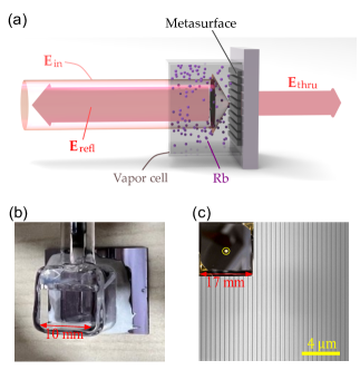
Our hybrid metasurface-atomic-vapor device is illustrated schematically in Fig. 1a. The device consists of an all-dielectric optical metasurface chip, which is composed of silicon nanogratings on a borosilicate glass substrate. A cubic quartz chamber is then bonded to this metasurface chip using low vapor pressure resin sealant. Further, a rubidium (Rb) dispenser pill is inserted and then the chamber is evacuated and sealed successively. Finally, the Rb atoms are released by focusing a semiconductor laser at onto the pill for a time duration of . The inner length of the cubic vapor cell is and a photograph of the hybrid cell is given in Fig. 1b.
As shown in Fig. 1a, the light beam is injected from the front transparent window into the vapor cell, interacted with thermal atoms and scattered by the nanogratings on the back chip. The reflected light will be back into the vapor and interacted with the atoms again. Consequently, at the normal incidence, an atom can see both the incident light and the reflected light coming from opposite directions. With the help of birefringence and dichroism of the metasurface, the intensity and SOP of the reflected light can be adjusted by changing the incident light’s SOP. Using this adjustable pump-probe configuration, the optical coherence of atoms can be altered by tuning the interaction between light and atoms, resulting in a change in their response. In principle, these modulations will be observed in both the reflectance and transmittance spectra of the vapor cells.
III Design and characterization of metasurface
In this hybrid vapor cell based pump-probe configuration, the incident light is referred to as the ’probe’, while the reflected light is termed as the ’pump’. To achieve the maximum pumping, a high reflectivity of metasurface is required. Generally, metal structured metasurfaces could bring very high reflectivity, but there are no transmitted lights. The spectrum of the probe light will be helpful in extracting the information of the interaction between light and atoms. With these considerations, we adopted an all-dielectric metasurface structure with high contrast gratings [38, 39, 40]. The high contrast gratings can offer a high reflectivity while allowing some light to pass through the cells. In fact, by changing the SOP of the incident light, both reflectivity and transmissivity can be adjusted using these nanogratings. In our device, the high contrast gratings are constructed from silicon wires on a glass substrate. Note that the absorption of these thin silicon wires is weak for incident light. We performed simulations to obtain a high reflectivity for TM polarized light using rigorous coupled wave analysis (RCWA) method. The gratings are designed in pitch with a duty ratio of 0.65 and the height of silicon wires is . A scanning electron microscope (SEM) image of the gratings is shown in Fig. 1c and the inset displays the corresponding metasurface chip, in which a 1-mm diameter circular area with the fabricated gratings is located in the center of the chip.
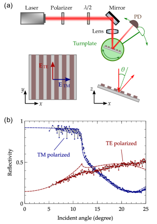
The metasurface device is characterized by measuring the reflectivity at different incident angles. The incident light is linearly polarized by a polarizer and then the direction of polarization is tuned using a half-wave plate as shown in Fig. 2a. The incident beam finally shines on the metasurface with a focusing lens and the reflected beam is detected by a photodiode (PD). To vary the incident angle, we used two electronically controlled turnplates to rotate the metasurface chip and the PD simultaneously. These all-dielectric gratings exhibit two eigenpolarization responses, corresponding to the TM and TE polarized incident lights (see the left inset of Fig. 2a). The zero-order reflection responses with respect to the incident angle are plotted in Fig. 2b. The definition of the incident angle is schematically shown in the right inset of Fig. 2a. As results shown in Fig. 2b, the measured reflectivities for both the TM and TE polarized incident lights are well matched with the simulated results. The results indicate that high reflectivity of for TM polarized light can be obtained at the normal incidence by using the fabricated metasurface. Meanwhile, the measured reflectance is only 0.16 for TE polarized light. In addition, the phase difference of the reflected light between these two polarizations is assessed by SOP measurement as . Therefore, it is possible to adjust the intensity and SOP of the reflected light in a wide range by changing the SOP of the incident light.
IV Theoretical analysis of the optical responses of the hybrid system
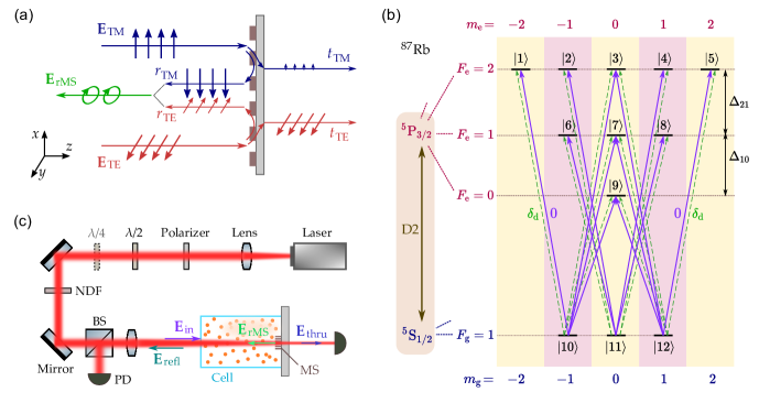
As the aforementioned description of the designed metasurface, the reflection and transmission responses for TM and TE polarized lights are different, i.e., an apparent birefringence is displayed. Specifically, the intensity and SOP of the reflected light could be dramatically adjusted by varying the polarization of incident light. Our designed metasurface has TM and TE polarizations as its eigenpolarizations, which means that any polarized incident light can be separated into such two polarized components for independent treatment, as shown in Fig. 3a. We assumed that the linearly polarized incident light is denoted by , where is the amplitude of light, is polarization angle, and () are the normalized TM (TE) polarized states. Moreover, the reflected light of the metasurface can be expressed as , where () are the complex reflection coefficients of TM (TE) polarized components. It is easy to find that the reflected light could be transferred to an elliptically polarized light, which is induced by the phase difference between and . Taking into account the interactions of atoms with both incident and reflected light, we choose the propagation direction (-direction) of light as the quantization axis for atoms. For simplicity, the incident light and the reflected light are rewritten with circular polarization states as
| (1) |
| (2) |
where are the spherical bases. Further, and can be redefined as and , respectively. The expressions of coefficients and can be obtained using equations (1) and (2). In this work, we will study the atomic spectra for the D2 transitions of Rb atoms. For the sake of simplicity, we use transitions of atoms to explain the modeling and computation process. The energy level diagram of atomic D2 line is shown in Fig. 3b. The purple solid and green dashed arrows represent the transitions caused by the pump and probe beams, respectively. As displayed in Fig. 3b, both of the transitions can be excited by the two light beams since their fields are not purely circularly polarized.
In the atomic vapor, Rb atoms moving with velocity along the light propagation direction experience the optical frequencies of the probe and pump beams as and , respectively, where is the optical angular frequency and is the wave number of the laser beam. We solve the following density matrix equation in a rotating frame with frequency :
| (3) |
where is the density operator, is the reduced Planck constant, () is the bare atomic (interaction) Hamiltonian, and denotes the dissipation process. The bare atomic Hamiltonian contains all the transition-related degenerate Zeeman sublevels, which are marked by to in Fig. 3b. The interaction Hamiltonian contains couplings of atoms with both the pump and probe beams. We can derive an effective electric susceptibility by obtaining steady-state solutions of the density matrix elements and averaging over the Maxwell-Boltzmann velocity distribution. For the components of the probe beam, the corresponding effective electric susceptibilities are given by:
| (4) |
where is the atomic number density of rubidium in the cell, is the decay rate of the excited state, is the Rabi frequency of the light beam (: transition dipole matrix element), is the most probable speed (: Boltzmann constant, : temperature of the cell, : mass of an atom), is the density matrix elements related with interactions of the probe beam, and is the normalized transition strength between the states and , the detailed derivation can be found in Supplementary Note 1. Thus the atomic effective refractive index can be deduced by
| (5) |
Finally, combining the atomic response of the Rb vapor and the optical response of the metasurface, the transmitted field of the hybrid cell can be deduced as
| (6) |
where () are the complex transmission coefficients of TM (TE) polarized lights across the metasurface, and is the length of the vapor cell. Using equations (1-6), the atomic transmittance spectrum of the hybrid system can be obtained. In short, when the polarization of the incident light deflects the eigenpolarizations of the metasurface (i.e., TM and TE polarizations), the reflected beam will be converted into elliptically polarized light. The followed atomic transitions and populations will be changed simultaneously. Moreover, there are multi-waves mixing and Zeeman coherences in the multiphoton processes. As a result, the atomic polarization and optical coherence are highly dependent on the SOP of the incident light. Finally, the light passing through the atomic vapor will be endowed these features and the effective electric susceptibility of the vapor can be evaluated with equation (4).
V Sub-Doppler atomic spectra
Figure 3c sketches the experimental setup for measuring the transmittance and reflectance spectra of the hybrid device, where the vapor cell is heated to . In Fig. 3c, a tunable laser operating near is used to sweep the wavelength of the incident light and linearly polarized by a polarizer. Then a half-wave () plate and a quarter-wave () plate are used to vary the direction and ellipticity of light’s polarization. Further, a neutral density filter (NDF) is utilized to attenuate the laser beam power. With a focusing lens, the laser beams have circular profiles with diameters of about when arriving at the metasurface, and both the transmitted and reflected light beams are detected with photodiodes.
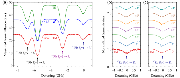
First, we present the spectra of linearly polarized light with varying polarization directions, which is accomplished by adjusting the optical axis angle of the plate (without using the plate). Figure 4a shows measured transmission spectra for the transition of the Rb D2 line for the cases of (TM), (TE) and linearly polarized incident beams with a power of . Due to the high polarization extinction ratio of the metasurface, the transmitted power increases when changing the incident beam from TM to TE polarization. The typical D2 line spectra of both the and atoms can be observed in the main shapes of the Doppler broadening lineshape. Each line has a spectral width of approximately , which includes a Doppler broadening width of , a natural linewidth of , and a number of other broadening contributions, such as a residual gas collision broadening and a limited interaction time between Rb atoms and the light beam. Specifically, the transmittance of linearly polarized light shows some differences comparing with those of TM and TE polarized lights, where the spectra for the hyperfine transitions of and are clearly demonstrated. To further analyze these differences, we focus to observe the last hyperfine transition spectra ( ) by adjusting the polarization direction of the incident light. The experimental results are displayed in Fig. 4b for different of the plate. The corresponding simulation results are shown in Fig. 4c. There are obvious resemblances between the simulated and the measured transmittance spectra.
As shown in Fig. 4b, for both the TM and TE polarized incident lights, the absorption spectra are similar to the spectrum of a single beam passing through a vapor cell. Due to the weak intensity of the incident light, the VSOP effect is currently not functional in the present pump-probe configuration. However, in the case of non-eigenpolarization incidence, the optical coherence and interference between two circular components can be observed. Since the two eigenpolarization components have different complex reflection coefficients, the incident light is converted into elliptically polarized light when it is not pure TM or TE polarized. According to the characterization results of the metasurface, the magnitudes of and are 0.93 and 0.16, respectively, where there is a phase difference of . In this pump-probe configuration, the left and right-handed circular components will not be balanced in the pump beam. The corresponding transitions will also be affected. Specifically, via the transition of , the ground populations of Zeeman sublevels are tilted due to the unbalanced pumping of the reflected lights. The induced variations of the optical coherences could be interrogated by the probe beam. It is important to stress that the transmittance spectrum is not obtained by simply multiplying the atomic response with the incident light. Due to the linear dichroism of the metasurface, the transmission coefficients of TM/TE polarized components are very different. The experimental results show that the magnitude of is about 0.72 while that is less than 0.01 for . Consequently, the metasurface is almost transparent for the TE polarized light. Using equation (6), we can observe that the overall transmittance is a result of interference between the left- and right-handed circular components, which incorporate the corresponding atomic responses (see Supplementary Note 2). Through these interactions, the sub-Doppler responses linked to the hyperfine structures can be resolved in our transmittance and reflectance spectra. As the measured transmittance spectra displayed in Fig. 4b, the sub-Doppler absorption dips are clearly presented for the cases of equaling , and . The corresponding reflectance spectra are shown in Supplementary Fig. S3, where the sub-Doppler features can also be observed. Hence, we have shown that the polarization direction of linear polarized light can be utilized to tune the atomic spectra in our system.
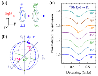
VI Altering sub-Doppler lineshape
To further illustrate the impact of the SOP of the incident light beam, we adjust the SOP of light via passing it through a cascade of a plate and a plate, as shown in Fig. 3c and Fig. 5a. Using this cascade setting, the SOP of light can, in principle, be adjusted to any state by varying the optical axes of both plates. In our experiment, we set a fixed angle of for the optical axis of the plate. The optical axis angle of the plate is varied to tune the SOP of incident light. These settings provide for the evolution of a SOP from linear polarization to circular polarization. The corresponding SOP trace is plotted in Fig. 5b with a blue dashed circle on the Poincaré sphere, in which a cycle evolution can be achieved by a variation of . In the experiment, is varied from to , meanwhile, the starting position of the SOP and the evolution direction are also indicated in Fig. 5b. The measured results of normalized transmittance spectra for the transitions of are presented in Fig. 5c. The sub-Doppler transparent peaks can be found at near circular polarizations of incident light, as the curves of , , and shown in Fig. 5c. In these cases, the incident light is nearly circularly polarized, while the reflected light is transferred to a elliptically polarized light. That is, the probe light interacts with Rb atoms solely through one of transitions. In this pump-probe configuration, the transmittance spectrum exhibits its sub-Doppler feature in the transparent instead of the absorption. When the incident SOP is adjusted from the circular to linear polarizations, the sub-Doppler transparent peaks will be converted to the sub-Doppler absorption dip (). This evolution of the sub-Doppler lineshape is analogous to the typical evolution for a two-path optical interference, in which the dispersion are moderated by the incident SOP incorporated with the thermal atoms.
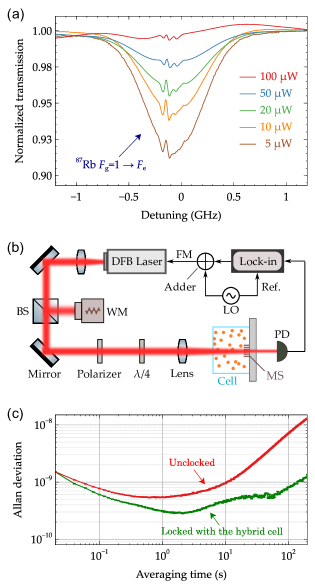
VII Power dependence and laser stabilization
To examine the effect of the beam intensity on the spectra, we performed the experiments with different powers of incident beam in the cases of circular polarization of the incident light. As shown in Fig. 6a, the transmission spectrum is changed by varying the power levels. The whole attenuation induced by the absorption of atoms is decreased as the increment of the power, which can be interpreted by the power dependence saturation mechanism of two-level systems. Meanwhile, the sub-Doppler lineshapes are altered due to the tuning of the incident light power level, as both the effective probe and the pump strength are changed. The sub-Doppler feature for each hyperfine transition is displayed clearly at the high incident power. However, there is a concurrent decrement in interference contrast. As the five curves shown in Fig. 6a, the transparent peak gives the best contrast at the power of . This sharp peak can be used to stabilize lasers. To demonstrate the performance of stabilization for a laser, we carried out the measurement with the experimental setup schematically shown in Fig. 6b. The distributed feedback (DFB) laser is modulated via frequency modulation of the injection current. Error signal is generated by using the lock-in amplifier to demodulate the transmission signal of the hybrid vapor cell. Then, the error signal is added to adjust the injection current to stabilize the DFB laser. The wavelength of the DFB laser is recorded by a high precision wavelength meter. The normalized Allan deviation of the measured laser wavelength is demonstrated in Fig. 6c. Comparing with the free running laser, the locked laser clearly shows a better wavelength stabilization with the Allan deviation of at , which may be limited by the resolution of the wavelength meter.
VIII Discussion and conclusion
In this work, the sub-Doppler responses for atomic hyperfine transitions were observed by using the metasurface integrated hybrid cell in both the transmissivity and reflectivity. Note that these sub-Doppler spectra do not require high light intensity, which differs from responses caused by the VSOP effect. Actually, the VSOP effect will dominate the sub-Doppler responses with the increment of incident power. Moreover, the sub-Doppler lineshape in our system can be altered by adjusting the SOP of the incident light. In the experiment, the transition from the sub-Doppler transparent peak to absorption dip was observed by changing circular polarization to linear polarization of the incident light. It is worth noting that these sub-Doppler spectra are the cooperation results of the atomic response of the thermal atoms and the optical response of the metasurface chip (see Supplementary Note 2).
To interpret the experimental spectra, we model this hybrid system and the calculations are in well agreement with the measured results. However, some of the details of the sub-Doppler atomic spectra do not match well, and there are several possible reasons. First, for the pump light, we did not consider the depletion of the probe light absorbed by the atoms, especially around the resonance. This depletion will affect the Rabi frequency of pump beam and the dispersion also varied since the absorption is frequency dependent. Further improvements may be achieved by iterative calculations between optical fields and density matrix equations. Second, the transfer of ground populations from one hyperfine level to another is not considered. In our calculations, we assumed that the transitions between each ground hyperfine level to their excited states are a closed system, but this is not a true condition in Rb atoms. The transfer of ground populations of this kind may be taken into account in future investigations. Third, the atom-surface interaction is not considered. In our hybrid cell, the metasurface structure can directly touch the atomic vapor. In such a condition, the interaction between near-field photons and atoms could happen, which may bring further spectrum broadening due to the limited interaction time and frequency shifts of transitions induced by the Casimir-Polder interaction [26, 37, 41, 42]. Additionally, the sub-Doppler lineshape is affected by the collisions between the residual gas molecules and Rb atoms. In our experiment, The vacuum level was not so good due to the limitation of vacuum extractor. In fact, by using our metasurface chip, the spectral linewidth of sub-Doppler responses can be reduced with a high vacuum vapor cell (see Supplementary Fig. S4).
In summary, we engineered a nanograting metasurface with operating wavelength corresponding to the D2 line of Rb atoms. The fabricated metasurface chip has been integrated with the miniature vapor cell. By utilizing the multifunction light control of the metasurface, we built a pump-probe configuration in the hybrid vapor cell and observed sub-Doppler spectra in our experiments. The lineshape of the sub-Doppler response can be tuned by changing the SOP of the incident light at low intensity. Spectrum transition from the absorption to the transparency was observed. By using one of the sub-Doppler transparent responses, the laser stabilization with instability at is achieved. Our study investigates the potential applications of optical metasurfaces in manipulating atomic spectra, which holds great promise for future advances in fundamental optics and innovative optical applications.
Acknowledgements
This work is supported by the Fundamental Research Funds for the Central Universities under Grant KG21008401.
Conflict of Interest. The authors declare no conflict of interest.
Data Availability Statement. The data that support the findings of this study are available from the corresponding author upon reasonable request.
Supporting Information. Supporting Information is available from the Wiley Online Library or from the author.
References
- [1] Ludlow, A. D., Boyd, M. M., Ye, J., Peik, E. & Schmidt, P. Optical atomic clocks. Rev. Mod. Phys. 87, 637–701 (2015).
- [2] Camparo, J. The rubidium atomic clock and basic research. Phys. Today 60, 33–39 (2007).
- [3] Diddams, S. A., Bergquist, J. C., Jefferts, S. R. & Oates, C. W. Standards of time and frequency at the outset of the 21st century. Science 306, 1318–1324 (2004).
- [4] Kitching, J., Knappe, S. & Donley, E. A. Atomic sensors – A review. IEEE Sens. J. 11, 1749–1758 (2011).
- [5] Fang, J. & Qin, J. Advances in atomic gyroscopes: A view from inertial navigation applications. Sensors 12, 6331–6346 (2012).
- [6] Kominis, I. K., Kornack, T. W., Allred, J. C. & Romalis, M. V. A subfemtotesla multichannel atomic magnetometer. Nature 422, 596–599 (2003).
- [7] Budker, D. & Romalis, M. Optical magnetometry. Nat. Phys. 3, 227–234 (2007).
- [8] Bize, S. et al. Cold atom clocks and applications. J. Phys. B: At. Mol. Opt. Phys. 38, S449–S468 (2005).
- [9] Hong, F.-L. Optical frequency standards for time and length applications. Meas. Sci. Technol. 28, 012002 (2016).
- [10] Pearman, C. P. et al. Polarization spectroscopy of a closed atomic transition: Applications to laser frequency locking. J. Phys. B: At. Mol. Opt. Phys. 35, 5141–5151 (2002).
- [11] Boto, E. et al. Moving magnetoencephalography towards real-world applications with a wearable system. Nature 555, 657–661 (2018).
- [12] Maguire, L. P., van Bijnen, R. M. W., Mese, E. & Scholten, R. E. Theoretical calculation of saturated absorption spectra for multi-level atoms. J. Phys. B: At. Mol. Opt. Phys. 39, 2709–2720 (2006).
- [13] Moon, G. & Noh, H.-R. Analytic calculation of linear susceptibility in velocity-dependent pump-probe spectroscopy. Phys. Rev. A 78, 032506 (2008).
- [14] Zigdon, T., Wilson-Gordon, A. D. & Friedmann, H. Absorption spectra for strong pump and probe in atomic beam of cesium atoms. Phys. Rev. A 80, 033825 (2009).
- [15] Harris, M. L. et al. Polarization spectroscopy in rubidium and cesium. Phys. Rev. A 73, 062509 (2006).
- [16] Brazhnikov, D. V., Taichenachev, A. V. & Yudin, V. I. Polarization method for controlling a sign of electromagnetically-induced transparency/absorption resonances. Eur. Phys. J. D 63, 315–325 (2011).
- [17] Brazhnikov, D. V. et al. High-quality electromagnetically-induced absorption resonances in a buffer-gas-filled vapour cell. Laser Phys. Lett. 15, 025701 (2018).
- [18] Rehman, H.-u., Adnan, M., Noh, H.-R. & Kim, J.-T. Spectral features of electromagnetically induced absorption in 85Rb atoms. J. Phys. B: At. Mol. Opt. Phys. 48, 115502 (2015).
- [19] Krasteva, A. et al. Observation and theoretical simulation of electromagnetically induced transparency and enhanced velocity selective optical pumping in cesium vapour in a micrometric thickness optical cell. J. Phys. B: At. Mol. Opt. Phys. 47, 175004 (2014).
- [20] Rehman, H. U., Mohsin, M. Q., Noh, H.-R. & Kim, J.-T. Electromagnetically induced absorption due to transfer of coherence and coherence population oscillation for the Fg=3→Fe=4 transition in 85Rb atoms. Opt. Commun. 381, 127–134 (2016).
- [21] Budker, D. et al. Resonant nonlinear magneto-optical effects in atoms. Rev. Mod. Phys. 74, 1153–1201 (2002).
- [22] Overvig, A. C. et al. Dielectric metasurfaces for complete and independent control of the optical amplitude and phase. Light Sci. Appl. 8, 92 (2019).
- [23] Kamali, S. M., Arbabi, E., Arbabi, A. & Faraon, A. A review of dielectric optical metasurfaces for wavefront control. Nanophotonics 7, 1041–1068. (2018).
- [24] Yu, N. et al. Light propagation with phase discontinuities: Generalized laws of reflection and refraction. Science 334, 333–337 (2011).
- [25] Rubin, N. A., Shi, Z. & Capasso, F. Polarization in diffractive optics and metasurfaces. Adv. Opt. Photon. 13, 836 (2021).
- [26] Achouri, K. & Caloz, C. Design, concepts, and applications of electromagnetic metasurfaces. Nanophotonics 7, 1095–1116 (2018).
- [27] Bao, Y., Ni, J. & Qiu, C.-W. A minimalist single-layer metasurface for arbitrary and full control of vector vortex beams. Adv. Mater. 32, 1905659 (2019).
- [28] Overvig, A. C., Malek, S. C. & Yu, N. Multifunctional Nonlocal Metasurfaces. Phys. Rev. Lett. 125, 017402 (2020).
- [29] Bar-David, J., Stern, L. & Levy, U. Dynamic Control over the Optical Transmission of Nanoscale Dielectric Metasurface by Alkali Vapors. Nano Lett. 17, 1127–1131 (2017).
- [30] Sebbag, Y., Talker, E., Naiman, A., Barash, Y. & Levy, U. Demonstration of an integrated nanophotonic chip-scale alkali vapor magnetometer using inverse design. Light Sci. Appl. 10, 54 (2021).
- [31] Yang, X., Benelajla, M., Carpenter, S. & Choy, J. T. Analysis of atomic magnetometry using metasurface optics for balanced polarimetry. Opt. Express 31, 13436–13446 (2023).
- [32] Xu, Y. et al. Atomic spin detection method based on spin-selective beam-splitting metasurface. Adv. Optical Mater. 2301353 (2023).
- [33] Hummon, M. T. et al. Photonic chip for laser stabilization to an atomic vapor with 10-11 instability. Optica 5, 443 (2018).
- [34] Zhu, L. et al. A dielectric metasurface optical chip for the generation of cold atoms. Sci. Adv. 6, eabb6667 (2020).
- [35] Ropp, C. et al. Integrating planar photonics for multi-beam generation and atomic clock packaging on chip. Light Sci. Appl. 12, 83 (2023).
- [36] Aljunid, S. A. et al. Atomic response in the near-field of nanostructured plasmonic metamaterial. Nano Lett. 16, 3137–3141 (2016).
- [37] Chan, E. A. et al. Tailoring optical metamaterials to tune the atom-surface casimir-polder interaction. Sci. Adv. 4, eaao4223 (2018).
- [38] Karagodsky, V., Sedgwick, F. G. & Chang-Hasnain, C. J. Theoretical analysis of subwavelength high contrast grating reflectors. Opt. Express 18, 16973 (2010).
- [39] Chang-Hasnain, C. J. & Yang, W. High-contrast gratings for integrated optoelectronics. Adv. Opt. Photon. 4, 379 (2012).
- [40] Qiao, P., Yang, W. & Chang-Hasnain, C. J. Recent advances in high-contrast metastructures, metasurfaces, and photonic crystals. Adv. Opt. Photon. 10, 180–245 (2018).
- [41] Stern, L., Desiatov, B., Goykhman, I. & Levy, U. Nanoscale light–matter interactions in atomic cladding waveguides. Nat. Commun. 4, 1548 (2013).
- [42] Ritter, R. et al. Coupling Thermal Atomic Vapor to Slot Waveguides. Phys. Rev. X 8, 021032 (2018).