Task-oriented Semantics-aware Communications for Robotic Waypoint Transmission: the Value and Age of Information Approach
Abstract
The ultra-reliable and low-latency communication (URLLC) service of the fifth-generation (5G) mobile communication network struggles to support safe robot operation. Nowadays, the sixth-generation (6G) mobile communication network is proposed to provide hyper-reliable and low-latency communication to enable safer control for robots. However, current 5G/ 6G research mainly focused on improving communication performance, while the robotics community mostly assumed communication to be ideal. To jointly consider communication and robotic control with a focus on the specific robotic task, we propose task-oriented and semantics-aware communication in robotic control (TSRC) to exploit the context of data and its importance in achieving the task at both transmitter and receiver. At the transmitter, we propose a deep reinforcement learning algorithm to generate optimal control and command (C&C) data and a proactive repetition scheme (DeepPro) to increase the successful transmission probability. At the receiver, we design the value of information (VoI) and age of information (AoI) based queue ordering mechanism (VA-QOM) to reorganize the queue based on the semantic information extracted from the AoI and the VoI. The simulation results validate that our proposed TSRC framework achieves a 91.5 improvement in the mean square error compared to the traditional unmanned aerial vehicle control framework.
Index Terms:
Task-oriented and semantics-aware, robotic control, AoI, VoI, DRL, proactive repetition scheme, C&C data.I Introduction
The field of robotics has experienced significant advancements in the past few decades, leading to widespread applications, such as agriculture [1], education [2], and surgery [3]. Wireless connectivity is important for the control of mobile robots (i.e., ground vehicles and unmanned aerial vehicles (UAVs)) [4], especially for tasks that require remote control and sensing [5]. Remote control of robots can benefit from the development of the fifth-generation (5G) mobile communication network [6], due to its ultra-reliable low latency communication (URLLC) service with a latency requirement as low as 1 ms [7, 8, 9, 10]. Unfortunately, this URLLC service defined in 5G is still unable to support the real-time safe operation of mobile robots [11]. In the context of high-speed mobile robots, even a mere 1 ms transmission delay can result in significant movement that cannot be neglected. In such case, the mobile robot may potentially collide with obstacles or pose a risk to the surrounding objects [12].
Compared to 5G, the sixth-generation (6G) mobile communication network [13] aims to provide a more stringent service requirement, known as hyper-reliable and low-latency communication, which demands a peak data rate ranging from 50 Gbps to 200 Gbps, latency within 0.1ms to 1ms, and reliability ranging from 1- to 1- [14]. 6G technology is expected to facilitate the remote control of mobile robots with accuracy, robustness, energy efficiency, and safety [11]. Until now, existing research has been mainly focused on improving the communication performance, such as the reliability [15], the data rate [16], and the latency [17].
On one hand, existing wireless communication works tend to ignore the behaviour and actuation performance of robotics, and only focus on improving the communication performance. On the other hand, existing robotics papers [18, 19, 20] mostly assumed wireless communication to be ideal with no packet loss or latency. Even in the case where robots are controlled remotely, as demonstrated in [20], the transmitter (remote controller) is responsible for periodically publishing control commands, and the receiver (mobile robot) stores the commands in a queue based on their time of arrival. However, the potential loss and delay of the packets caused by the practical wireless channels are always ignored by the robotics community. Therefore, there is a big research gap on how to jointly consider and optimize wireless communication and robotic control with a focus on specific robotic tasks, such as tracking, navigation, etc.
To fill this gap, task-oriented/ goal-oriented communication has been proposed in [21] to design the communication system/ network with a focus on the effectiveness of communication in accomplishing a specific goal/ task. In the robotics field, the effectiveness of controlling the robots wirelessly can be measured by effectiveness level performance metrics, such as the mean square error (MSE) [22] and the tracking accuracy [23]. In [24], the authors proposed a deep reinforcement learning (DRL) method to choose the optimal segment length and sampling rate for the physical world trajectory transmission of a robotic arm, with the aim to improve the tracking error measured by the MSE between the trajectory of the device and its digital model. Even though [24] optimized task-oriented performance (i.e., tracking error), the meaning and importance/ significance behind the meaning of bits are completely ignored.
To enable more accurate, context-aware, and efficient communication, semantic communication has been introduced to solve the semantic-level problem [25]. Different from the well-studied technical-level problem that focuses on how to reliably transmit all the bits, the semantic-level problem considers how to convey semantic information precisely and serves as the foundation for the effectiveness-level problem [26]. The semantic information has two main definitions. One is defined as the meaning of the information, which pertains to what the information is intended to express and how it relates to the world around it, entailing a focus on syntax [26]. This definition has mainly considered for text data type, where the bilingual evaluation understudy (BLEU) score is introduced to evaluate the sentence similarity for machine translation [27], signal-to-distortion ratio (SDR) and perceptual evaluation of speech distortion (PESQ) are used to evaluate speech signal reconstruction [28].
The second definition pertains to the significance and importance of information [29], which evaluates the importance of extracted semantic information in accomplishing a specific task and is closely coupled with the considered task. Depending on the task/ goal, the significance of information can be evaluated based on various new metrics, including the age of information (AoI), the value of information (VoI), just noticeable difference [21], the skeleton of the avatar [30], and et. The AoI is defined as the duration elapsed since the information was first generated and is widely used to effectively characterize latency in the real-time status update system [31]. In [32], the authors proposed a semantics-aware approach to address the problem of active fault detection in an IoT scenario. A stochastic approximation algorithm was employed to jointly consider the importance and purpose of the information to detect faults and how to acquire fresh information more effectively. In this approach, the AoI was utilized to evaluate the freshness of the sensor information, and the semantic information was measured by a function as VoI, which was related to the AoI and the entropy of the probability distribution over the operational status. The concept of VoI is commonly defined as the value/ significance of the information in completing communication tasks and can be utilized as a metric to quantify the significance of semantic information [33, 34]. Depending on the task/ goal, VoI has been represented based on various metrics, such as the importance of the extracted features to the accurate classification [33], the cost for wrong actuation [35], and structural index similarity (SSIM) [36].
To incorporate semantic level consideration into the task-oriented communication framework, a generic task-oriented and semantics-aware (TOSA) communication framework was proposed in [21]. This framework jointly considered the semantic level information and effectiveness level performance metrics, for different tasks with various data types. Although TOSA has been applied in various domains [37, 30, 38], there is little research on the command and control data for robotics. In [39], the TOSA communication framework was studied for the downlink control and command (C&C) signal transmission, which characterized semantic information as a function of AoI and the similarity between adjacent C&C signals. This study effectively reduced redundant packet transmissions by utilizing a DRL-based TOSA optimization method. However, it lacks the design for effectiveness level metrics and the receiver design.
To fill this gap, we propose task-oriented and semantics-aware communication in robotic control (TSRC) in a real-time UAV waypoint transmission task. Compared to traditional transmitter/receiver design and previous works [20, 24, 32, 35, 39], we design the DRL at the transmitter to generate the optimal C&C data to accomplish the task, adopt the proactive repetition scheme for C&C data transmission, order the queue of received C&C data based on their semantic information extracted from the AoI and the VoI, and utilize the MSE as our effectiveness level metric. To the best of our knowledge, our contributions can be summarized as follows:
-
1)
We consider a scenario involving a base station (BS) and a UAV with a dynamic communication environment. In this setup, the BS acts as the transmitter, periodically transmitting C&C data to the UAV to manoeuvre it to fly along a trajectory. Our goal is to collaboratively consider the communication and control procedures on both the BS and UAV sides, with the aim of minimizing the positional error between the actual flight trajectory of the UAV and the target trajectory.
-
2)
We propose task-oriented and semantics-aware communication in robotics control (TSRC), which includes DRL-based C&C data generation with the proactive scheme for repetition (DeepPro) and the VoI and the AoI based queue ordering mechanism (VA-QOM). At the semantic level, the TSRC employs the DeepPro on the BS side, facilitating the generation of more appropriate C&C data to accomplish the task and elevating the probability of successful transmission compared to conventional frameworks. Meanwhile, on the UAV side, the VA-QOM is deployed by utilizing the combined function of AoI and VoI to extract the semantic information of received C&C data in the queue, which can measure the importance of each C&C data at the present moment and has the potential to be extended to other time-sensitive control applications. At the effectiveness level, we choose the MSE between the actual flight trajectory of the UAV and the target one as the performance metric.
-
3)
To evaluate the effectiveness of the proposed TSRC framework, we implemented it in a real-time UAV trajectory control task and compared it with the traditional UAV control framework via simulation. The simulation results indicate that the proposed TSRC framework achieves 91.5 improvement in the mean square error compared to the traditional UAV control framework.
The rest of the paper is organized as follows: In Section , we present the system model and problem formulation. Section and Section introduce the design of the traditional UAV control framework and the proposed TSRC framework, respectively. In Section , the simulation results is presented. Finally, Section concludes this paper.
II System Model and Problem formulation
In this section, we introduce a real-time UAV waypoint transmission task, where a BS controls a UAV to fly alongside a trajectory in real time by sending C&C data. Subsequently, we model the communication environment for downlink C&C data transmission. Based on that, we present the problem formulation and the evaluation metric.
II-A Real-time UAV Waypoint Transmission Task
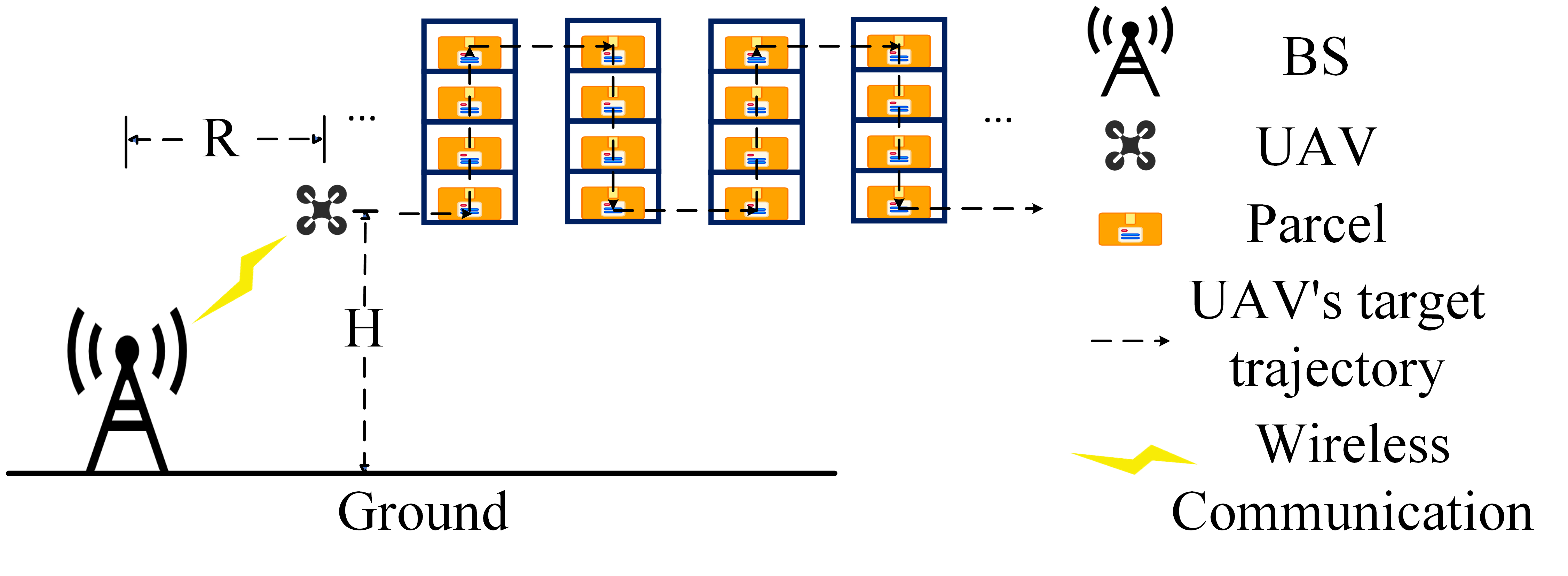
We consider a real-time UAV waypoint transmission task, where a BS serves as a remote controller to generate C&C data to control a UAV to fly alongside a trajectory in real time. The trajectory is composed of a series of waypoints, which are specific geographic locations and serve as reference points for navigation. In the task, the BS only has knowledge of the UAV’s target waypoint in the next time slot. As a result, the BS must transmit the corresponding C&C data in real time. By executing the received C&C data, the UAV flies across various positions or waypoints at different timestamps. One user case is shown in Fig. 1, where the BS needs to control the UAV in real time to scan QR codes on the parcels located at various positions. To effectively complete the task within the time constraint, the UAV aims to reach each waypoint on time.
II-B Channel Model
We assume that the BS remains stationary throughout the communication, and the UAV flies within a circular horizontal disk with a radius of R and a height of H, as shown in Fig. 1.
Considering both line-of-sight (LoS) and non-line-of-sight (NLoS) conditions for flying UAVs, we utilize free-space path loss and Rayleigh fading to model the path loss from the BS to the UAV as
| (1) |
where is the distance between the UAV and the BS, denotes the transmission frequency, is the speed of light, represents the path loss exponent, denotes the Rayleigh small-scale fading which follows , and and represent the path loss coefficients of LoS and NLoS cases, respectively. In Eq. (1), the the LoS probability is derived as
| (2) |
where is the evaluation angle of the UAV, is the flight height of the UAV, and and are positive constants related to the environment. Based on Eq. (1) and Eq. (2), the downlink channel from the BS to the UAV can be derived as
| (3) |
Based on Eq. (3), the signal-to-noise ratio (SNR) can be formulated as
| (4) |
where is the transmit power of the BS, is the channel gain, and is the Additive White Gaussian Noise (AWGN) power. Then, we can derive the transmission time for each generated C&C data as
| (5) |
where is the size of each C&C data, and is bandwidth. In downlink transmission, the UAV can only successfully decode the C&C data when the SNR of C&C transmission exceeds a specific threshold denoted as . The parameter that determines whether C&C data can be successfully decoded is expressed as
| (6) |
The C&C data can be successfully decoded if , otherwise, the C&C data can not be decoded. Meanwhile, if one C&C data is successfully decoded, we assume that it is not distorted and can be accurately recovered.
II-C The General Communication and Control Process
To provide an overview of the general communication and control process for the task, we introduce the C&C data transmission protocol and the queue employed to store the received C&C data.
II-C1 C&C Data Transmission
The BS starts to generate and transmit the C&C data periodically at the beginning of transmission time interval (TTI) , where and is the maximum value of . The time duration of each TTI is fixed as a constant . If the UAV successfully receives and decodes the C&C data , it will send an acknowledgement (ACK) to the BS. Otherwise, it will send a negative acknowledgement (NACK) to the BS. The parameter that determines to send ACK or NACK is presented as
| (7) |
where is the transmission result (success or failure) for . If , the UAV sends ACK. Otherwise, the UAV sends NACK.
II-C2 Queue
The queue of a UAV is a crucial component of the UAV’s control system, serving as a structured list of commands and instructions to be executed. When the UAV successfully receives and decodes one C&C data, it will store the C&C data in the queue with a predefined size . The size is not fixed in all scenarios and can be customized for the needs of a particular task. If the number of received C&C data exceeds , the C&C data with lower priority will be discarded. The priority can be measured by various metrics, such as the arrival time and the semantic information. The UAV ranks the C&C data in the queue based on their priorities and executes the C&C data according to the order. This adaptability allows for efficient task management and execution, ensuring that the UAV can effectively handle different scenarios and workloads as needed.
II-C3 The Overall Process
We assume that the time duration of the whole process is . The UAV’s actual position and target position at can be represented as and , respectively. At the beginning of TTI , the BS generates and transmits the C&C data with the execution time of the length of one TTI , expressed as
| (8) |
where , , and are the UAV’s planned velocity on the x-axis, y-axis, and z-axis for the TTI, respectively. Upon successfully receiving and decoding the C&C data , the UAV sends an ACK back () to the BS. Otherwise, the UAV sends a NACK () instead. When the UAV successfully receives and decodes , it will store it in the queue and rank all the received C&C data in the queue. By executing the C&C data in the queue according to their order, the UAV’s position is updated. It is important to note that, at the end of TTI , the UAV sends its real-time position back to the BS, where , , and are the UAV’s position on the x-axis, y-axis, and z-axis, respectively. To focus on the downlink transmission, we assume the uplink transmission (i.e., ACK, NACK, and ) from the UAV to the BS is ideal without packet loss or delay.
II-D Problem Formulation and Performance Metric
Due to the delay and packet loss in the downlink transmission of C&C data, there is often a discrepancy between the UAV’s actual trajectory and the UAV’s target trajectory. Consequently, we utilize the mean square error (MSE) to measure the gap between the two trajectories. Specifically, we aim to minimize the MSE between the positions of the actual trajectory and their corresponding positions of the target trajectory at the end of each TTI. We assume that each TTI can be uniformly divided into time duration. For time duration in TTI where , its timestamp is represented as . In this way, we can obtain the corresponding positions of the UAV’s actual trajectory and the UAV’s target trajectory . When is infinity, the average MSE of these two positions represents the MSE of the two trajectories. As a result, the problem can be formulated as
| (9) |
where is the Frobenius norm used to calculate the distance of the two positions.
Similar to the problem formulation, we utilize the MSE between the UAV’s actual trajectory and target trajectory as the performance metric. To simplify the calculation, instead of obtaining the positions of infinity time duration, we set as a fixed constant and the performance metric can be calculated as
| (10) |
III Traditional UAV Control Framework
In this section, we introduce the traditional UAV control framework as the baseline scheme. As shown in Fig. 2, it includes the design at the BS side and the UAV side. The BS consists of two main components: the C&C data generator and the transmitter. The C&C data generator is responsible for generating the C&C data at the beginning of each TTI. The transmitter includes an encoder, a modulator, and an antenna, which is used to convert the C&C data to the waveform and broadcast it to the wireless channel.
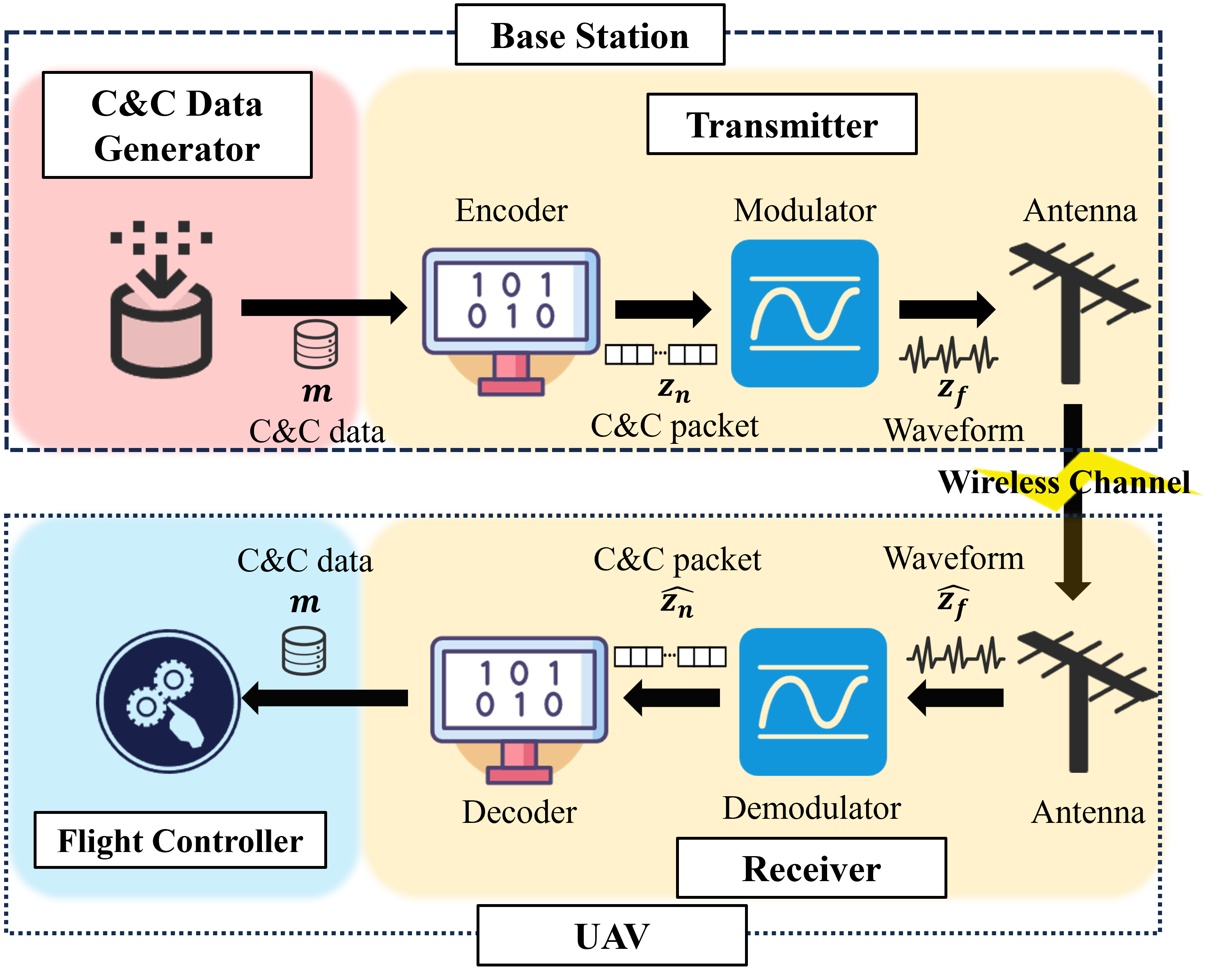
At the UAV side, it comprises a receiver and a flight controller. The receiver consists of an antenna, a demodulator, and a decoder, which is able to recover the C&C data from the received waveform if the C&C data can be successfully decoded (i.e., ). In the traditional UAV control framework, the queue size is set to one, and the queue is ordered by the arrival time of the C&C data. Therefore, only the newly arrived C&C data is stored in the queue of the UAV’s memory, and delivered to the flight controller. The UAV’s flight controller is able to convert the received C&C data into direct commands (velocity and the execution time ), which are used to control the UAV to accomplish the specific task.
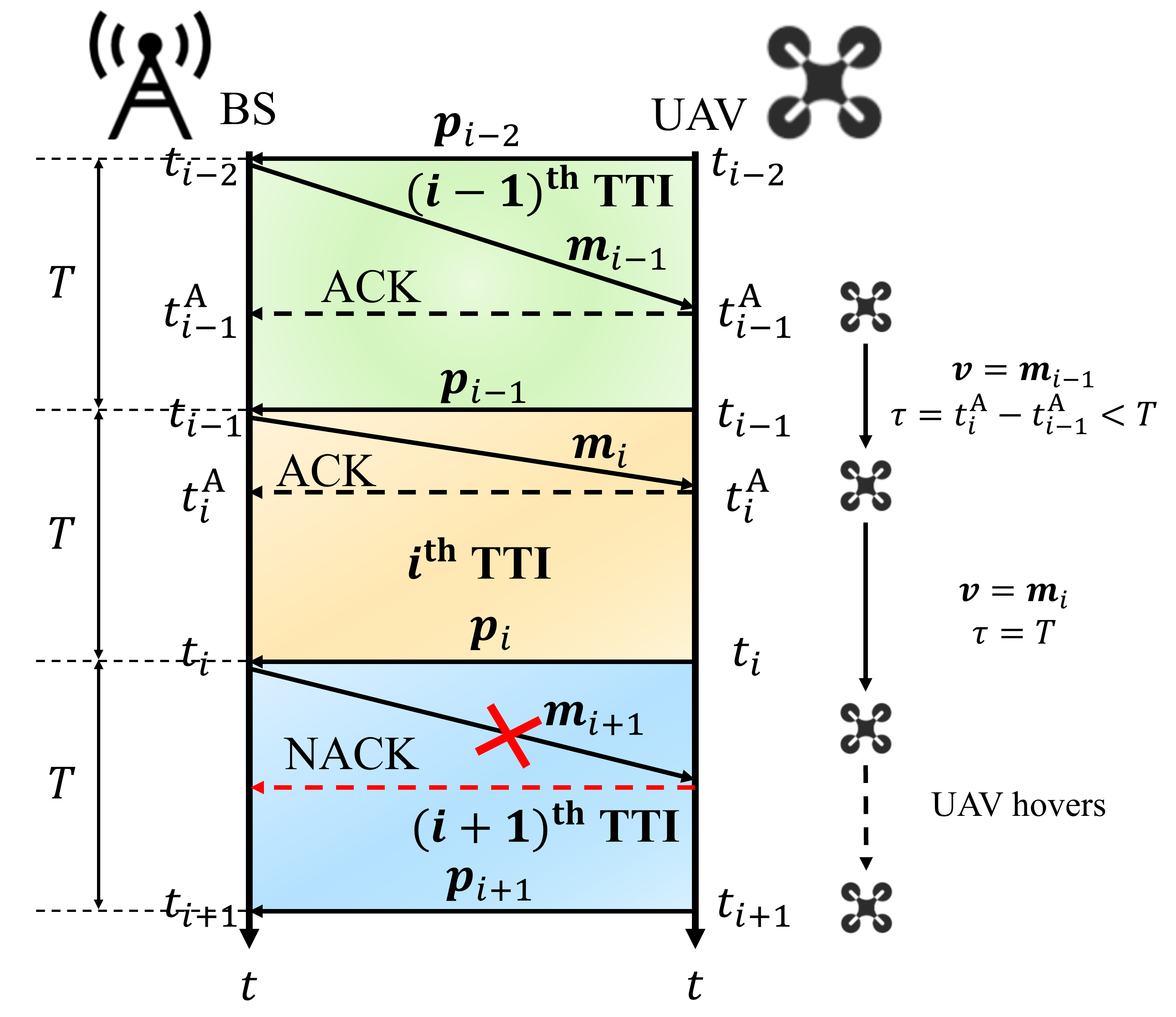
By assuming the C&C data processing time at both the BS and the UAV sides can be neglected, we plot an exemplar timeline of the BS and the UAV in the traditional UAV control framework shown in Fig. 3. At the beginning of TTI , the BS transmits the C&C data to the UAV. Once the UAV successfully decodes at , it will fly in a constant speed . If the UAV successfully decodes new C&C data when executing the ongoing C&C data at , it will discard the ongoing C&C data and start to execute the new C&C data . After finishing executing the C&C data , the UAV remains hovering until one new C&C data is successfully decoded.
The design of the traditional UAV control framework is shown in . At the beginning of TTI , the UAV’s current position is updated. By utilizing the channel model, we can obtain the transmission result and transmission time for the C&C data . Subsequently, all the successfully decoded C&C data in TTI can be obtained, which can be utilized to update the UAV’s position. The algorithm iterates until all the real-time C&C data are transmitted.
IV The Proposed TSRC Framework
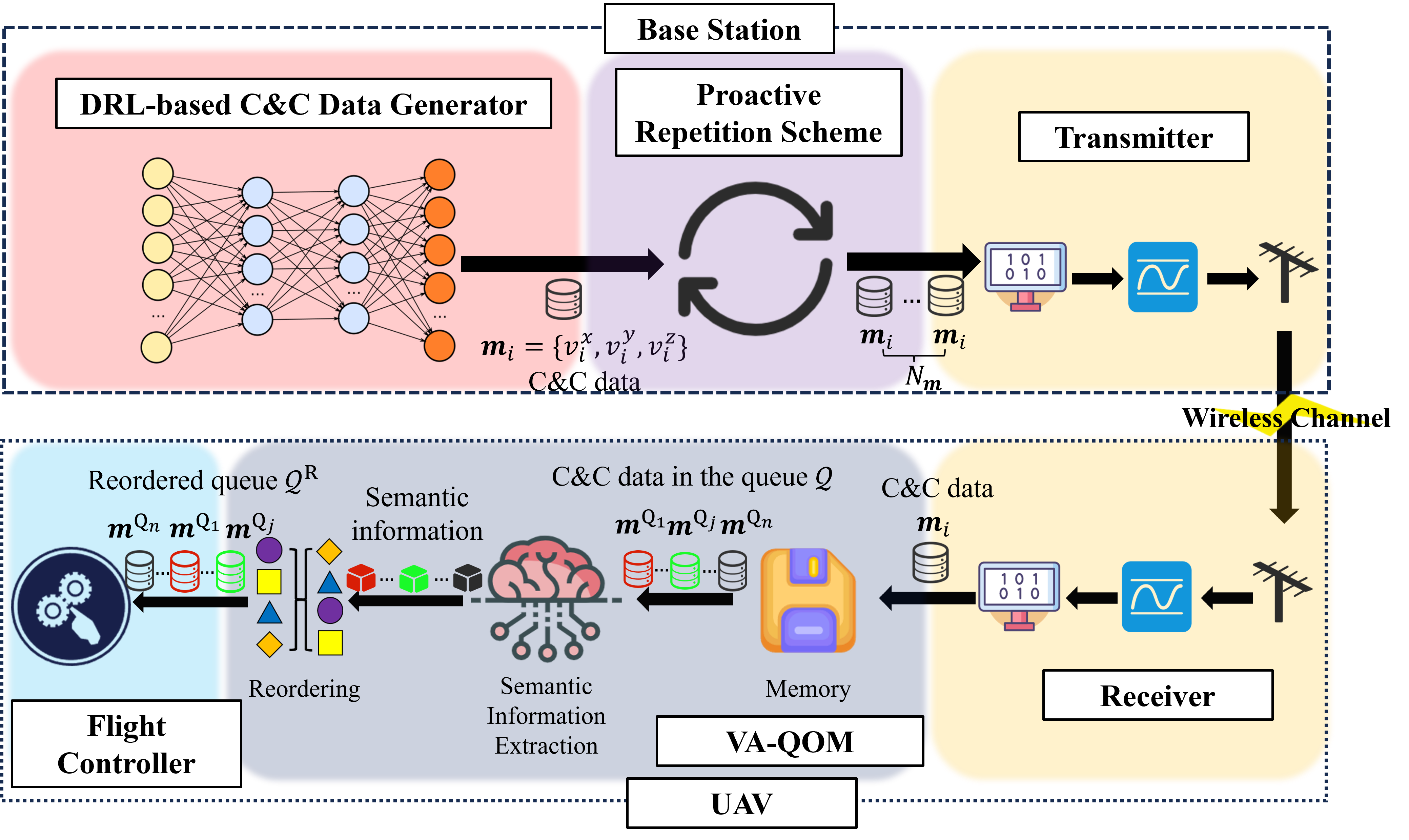
In this section, we propose TSRC framework which incorporates the semantic level design into the effectiveness level metric. As shown in Fig. 4, compared with the traditional UAV control framework, our proposed TSRC framework includes the DRL-based C&C data generator with proactive repetition transmission, namely, DeepPro, at the BS, and the VoI and the AoI based queue ordering mechanism (VA-QOM) at the UAV.
IV-A DeepPro at the BS
At the BS, we design a DeepPro scheme, which is expected to generate optimal C&C data for the real-time UAV waypoint transmission task via the DRL-based C&C data generator and increase the probability of successful transmission for each C&C data via the proactive repetition transmission.
IV-A1 DRL-based C&C Data Generator
To generate optimal C&C data at the beginning of each TTI, we need to obtain the influence of this C&C data on the task performance, which is related to the gap between the UAV’s actual positions and the UAV’s target positions of future TTIs. We define the state of the TTI as , where , , and are the UAV’s position on the x-axis, y-axis, and z-axis at the beginning of TTI , respectively. We aim to tackle the problem of optimizing the C&C data generation defined by the action parameter at TTI, where , , and are the UAV’s planned velocity in x-axis, y-axis, and z-axis, respectively. At the beginning of TTI , the agent at the BS makes the decision by accessing all prior historical observations for all previous TTIs , where the observation consists of the following variables: the UAV’s actual position and the UAV’s target position at . It is noted that the observation in each TTI includes all histories of such measurements and past actions, which is denoted as .
To obtain the impact of the C&C data generated at the start of TTI , the BS aims at minimizing the distance between the UAV’s actual positions and the UAV’s target positions in future TTIs. The optimization relies on the selection of parameters in according to the current observation history with respect to the stochastic policy , which can be formulated as
| (11) |
where is the discount factor for the performance accrued in future TTIs, and is the distance between the UAV’s actual position and target position at the end of TTI . Based on that, the reward is formulated as
| (12) |
It is noticed that the smaller the distance is after selecting one action, the higher the reward this action has.
The C&C data selection process at the BS is the Markov Decision Process because the state is only related to its previous state and past action. We define as a set of actual environment’s states with variables of the UAV’s positions at a certain time and channel parameters. The fact is that the BS cannot fully observe actual states in , while it can only access variables of without channel parameters. Meanwhile, the packet loss or delay decided by the channel parameters influences the transition between any two successive states. Since the channel parameter cannot be assessed by the BS, the process of state transition is not fully observed, which introduces a generally intractable Partially Observable Markov Decision Process (POMDP) problem.
To tackle this problem, we design the deep-Q network (DQN) algorithm, as one powerful DRL approach. The agent of the DQN algorithm is deployed at the BS to choose optimal actions by exploring the environment. During the training process, learning takes place over multiple episodes, with each episode including TTIs.
From the environment perspective, when it receives an action from the agent which is in state , it responds by providing the action’s reward and the agent’s next state . From the agent perspective, it receives the sample and stores it in the replay memory. The replay memory serves as a buffer that stores past experiences for the agent to learn from. Once the replay memory stored enough samples, the agent randomly selects a batch of samples for training. During the training process, the current state and its corresponding action are inputted to the Q-network, which calculates the predicted value using the function . Here, represents the parameter vector of the Q-network. Simultaneously, the next state and the reward are passed to the target Q-network, which is a separate network used for calculating the target values. Then, they pass the results to the loss function calculation parts, and the gradient of the loss function is calculated and utilized to update the parameter vector in the Q network. The gradient of the loss function is given as
| (13) |
where is updated by
| (14) |
where is the learning rate of RMSprop. In the training process, it is noted that the parameter vector in the target Q-network is updated by copying the parameter vector from the Q-network for every episodes. By selecting a batch of samples from the replay memory instead of a single sample, using two networks with the same structure but different parameters (the Q-network and the target Q-network), and updating the parameter vector periodically, the stability of the learning process is improved.
To balance the relationship between exploration and exploitation, we adopt the greedy approach in our learning process with the condition that . In each TTI, the agent randomly generates a probability and compares it with . If the probability is less than , the agent randomly chooses an action in this TTI. If not, the agent chooses the optimal action.
Based on that, we implement the DQN algorithm, which is presented in . At the beginning of TTI, the agent at the BS selects an action which is utilized to form the C&C data , and the BS transmit to the UAV. At the end of this TTI , the UAV sends its position to the BS. Then, the agent can obtain the next state and reward . As the algorithm iterates, the parameters can be updated and optimal actions can be selected.
IV-A2 Proactive Repetition Scheme
Due to the unstable communication channel, the packet loss and delay of downlink C&C data transmission can be harmful to the task accomplishment. In order to increase the successful transmission of the C&C data, we introduce the proactive scheme which is proposed in uplink transmission and has been proven to have the lowest latent access failure probability (the failure probability within a limited time) among the reactive scheme, K-repetition scheme and itself [40]. In the proactive scheme for uplink transmission, the user equipment (UE) repeats the transmission for a maximum number of repetitions, where the period to send each repetition is denoted as . The UE is configured to repeat the transmission for repetitions but can receive feedback after each repetition. This allows the UE to terminate repetitions earlier once receiving positive feedback (ACK).
Different from the uplink transmission without the latency constraint, in our work, we focus on downlink transmission with stringent delay limitations. Thus, we do not take retransmission into consideration. The exemplar timeline between the BS and the UAV for the downlink C&C data transmission is shown in Fig. 5.
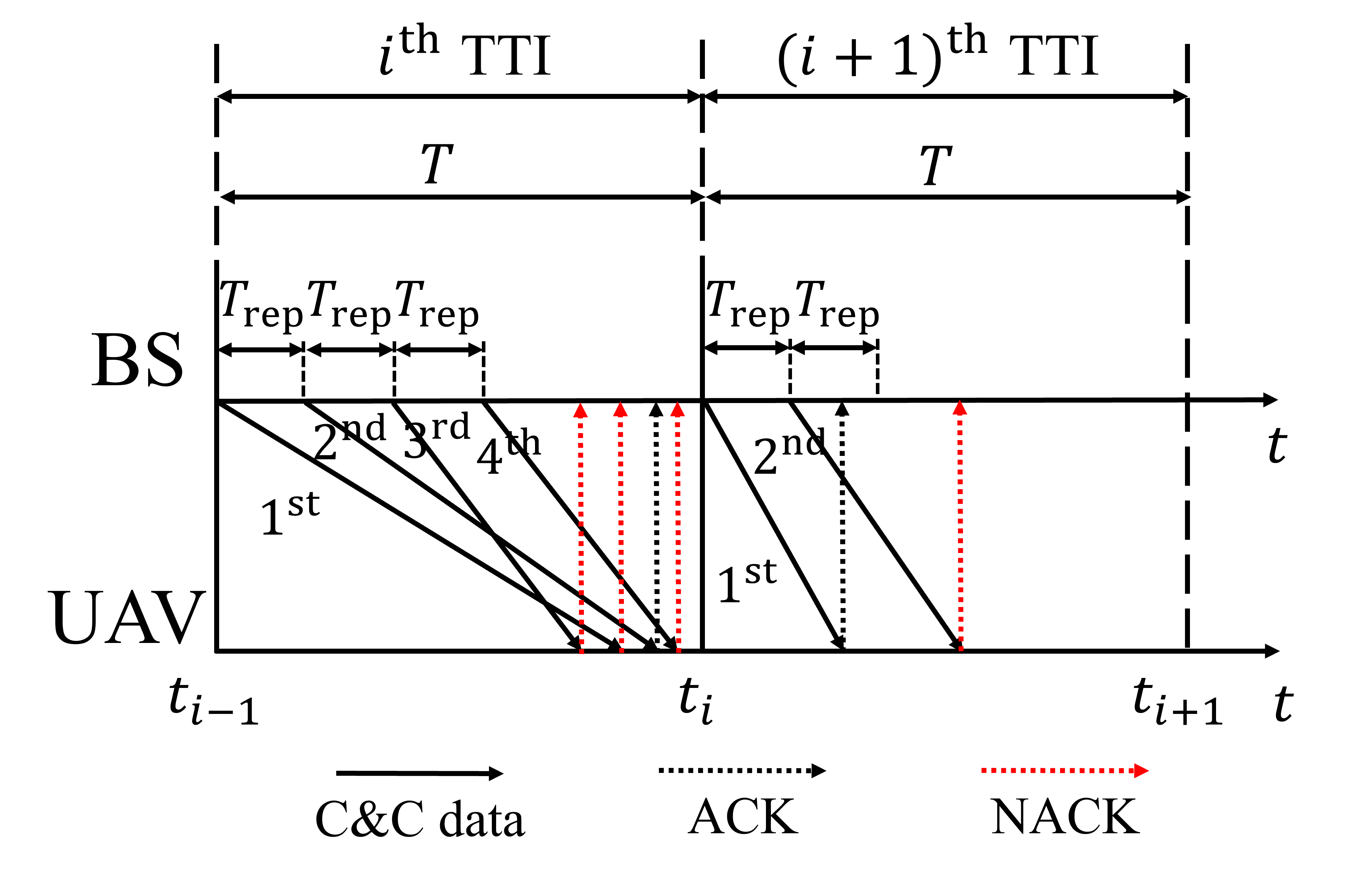
We make the assumption that the data (i.e., C&C data, ACK, etc.) processing time is ignored. Then, the important parameters of the proactive repetition scheme are and . In this example, the maximum repetition number is set to be 4. In the TTI, only the repetition is successfully received by the UAV and its corresponding ACK arrival time is larger than the transmitting time of the repetition. As a result, there is no repetition terminated at the BS and the number of repetitions is . By contrast, in the TTI, the ACK of the repetition is successfully received before the transmitting time of the repetition. Hence, the repetition is terminated and there are only two repetitions. It is worth noticing that the time duration between the first repetition and the maximum repetition should not exceed the threshold which is set to be the length of one TTI .
The implementation of the proactive repetition scheme is presented in . After one C&C data is generated, its () repetition occurs at . In the time duration between two consecutive repetitions, the UAV’s position may change, which may influence the transmission process (i.e., transmission result and transmission time ) of future repetitions. As a result, we need to calculate the UAV’s position in the time duration , where can be expressed as
| (15) |
If , this means there is no future repetition of , the end of this time duration is the beginning of the next TTI . Otherwise, is the transmission time of the next potential repetition .
Since the queue at the UAV only stores the earliest successfully decoded C&C data for TTI despite the number of successful repetitions it receives, we also need to obtain the smallest arrival time of all successfully decoded repetitions and consider it as the arrival time of . Based on the arrival time of all C&C data in the successfully decoded C&C data set , we can obtain the C&C data arrived during and update the UAV’s position. This loop continues to iterate until the number of repetitions reaches or the repetition is terminated when the ACK of the earliest successfully decoded repetition arrives at the BS ().
IV-A3 DeepPro
The DeepPro at the BS is designed by integrating the proactive repetition scheme into DRL-based C&C data generation. In TTI, the DRL-based C&C data generator generates a C&C data based on , and the proactive repetition scheme repeats the transmission of several times and the UAV’s position is updated based on . Next, the UAV’s position at the end of the TTI is obtained and utilized to acquire and . Finally, the sample is fed in the DQN training process in .
IV-B VA-QOM
With the aim of executing the optimal C&C data in the queue to accomplish the task, we design a VA-QOM scheme to control the UAV to fly to the target position as close as possible, where the size of the queue is set to be . Different from the traditional UAV control framework where the queue is ordered by the arrival time, we organise the queue of received C&C data according to their semantic information based on its importance, which is described by the AoI and the VoI.
IV-B1 AoI Design
Since the packet loss and transmission delay may cause negative impacts (i.e., delayed response time and wrong actions of the UAV) on the accomplishment of our time-sensitive task, it is crucial to utilize the AoI to evaluate the freshness of the packet. In our task, the AoI of the C&C data can be formulated as , where is the current time and is the generation time instance. We can observe that the higher the AoI is, the less fresh the C&C data is.
IV-B2 VoI Design
In our task, we aim to decrease the difference between the UAV’s actual trajectory and its target trajectory, which is equivalent to decreasing the distance between the UAV’s actual positions and the UAV’s target positions at each TTI. It is important to note that different C&C data may have different importance or value to the task to be executed, and the value of the same C&C data may change according to time. Concretely, at the same time, different C&C data may control the UAV to move closer or further to its target position, which implies different values. For the same C&C data, even though the content of data (i.e., planned velocity) is the same, the target position of the UAV may vary from time due to dynamics during transmission. To quantify the value of the C&C data in the current time , we introduce the VoI, denoted as .
We assume that when the UAV ranks the queue and executes the C&C data according to the order at , there is () C&C data in the queue (). Based on the assumption, for any queue updating time , the index of TTI of this queue updating time is written as
| (16) |
where is the floor function. Whenever the queue is updated, the first C&C data in the queue will be executed at the flight controller.
At time , the UAV aims to fly to the its target position as close as possible at . As the UAV has no direct knowledge about its target position and cannot know its actual future position , we propose a method for the UAV to estimate them. The estimated target position of the UAV at is denoted as . For the estimated actual position of the UAV at , due to that different C&C data in the queue may control the UAV to fly to different positions, different C&C data has different UAV’s estimated actual position . For the C&C data in the queue, if its estimated actual position is closer to the estimated target position , it will be more valuable. As a result, we define the VoI of as
| (17) |
where is the Frobenius norm used to calculate the distance between the estimated actual position and estimated target position at . The lower this distance is, the more valuable or more important this C&C data is.
Next, we present how we obtain and , respectively. We define as the latest position where the BS expects the UAV to reach, which can be obtained in two steps, as shown in Fig. 6.
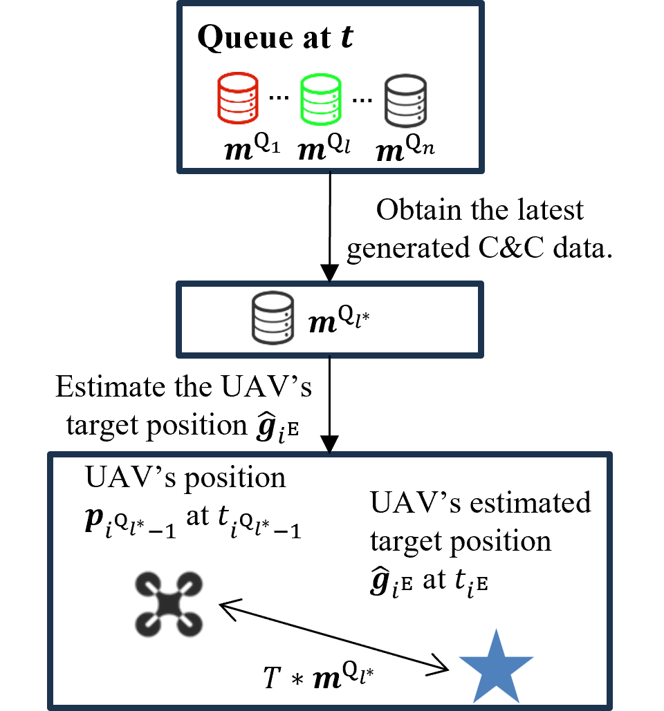
First, we calculate the AoI of all C&C data in the queue to find the latest generated C&C data . For C&C data , its AoI is calculated as
| (18) |
where is the generation time of . Based on that, we can obtain the index of the C&C data in the queue with the smallest AoI as
| (19) |
Second, due to the C&C data is the planned velocity vector of the UAV and its planned execution time is , we are able to attain the planned movement of the UAV as . Based on that, we estimate the target position for the UAV at time as
| (20) |
where is the UAV’s actual position at the generation time of the C&C data in the queue.
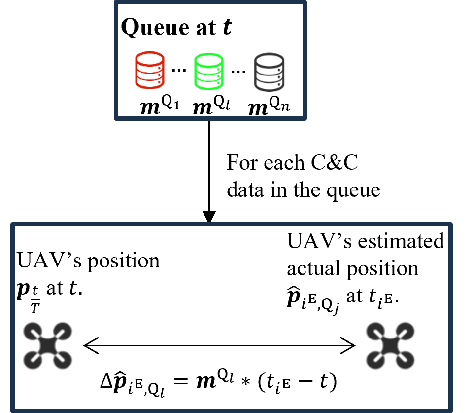
Then, we estimate the UAV’s actual position for the C&C data in two steps, as shown in Fig. 7. First, as the queue is updated at , the UAV will execute the C&C data from to , with the movement as
| (21) |
Second, since the UAV know its current position at , we estimate the actual position of the UAV at time as
| (22) |
After estimating and , the VoI of the C&C data can be calculated using Eq. (17).
IV-B3 Semantic Information Extraction
As the optimal C&C data for one TTI is generated at the beginning of this TTI, the C&C data in the queue is most valuable for the UAV if its AoI is less than . Otherwise, its semantic information only depends on its VoI. To normalize the range of semantic information, we define the function of semantic information for as
| (23) |
where the function is formulated as
| (24) |
If , is just generated at the beginning of this TTI, thus it has the highest semantic information which is equal to 1. Otherwise, is assumed to be outdated and its decides its importance to the task. As the increases, its semantic information increases and the upper bound is 1. At the beginning of TTI or when the UAV successfully decodes one new C&C data at , the UAV starts to order the queue based on the semantic information in a descending order, as shown in .
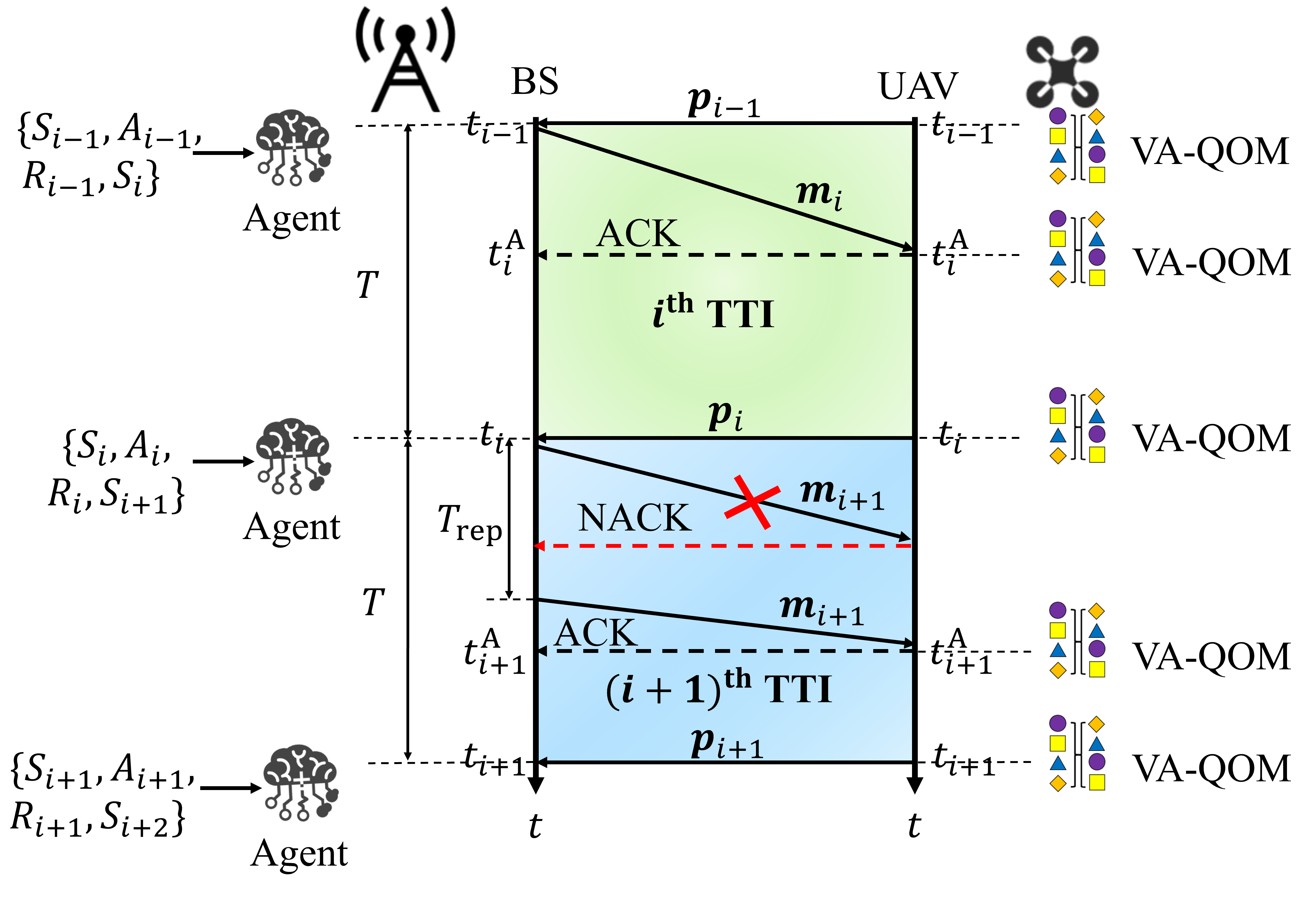
IV-C Communication and Control Process
As shown in Fig. 8, we plot the exemplar timeline of the BS and the UAV to introduce the communication and control process in our proposed TSRC framework. At the beginning of TTI , the agent at the BS selects the action from past observations to generate the C&C data which is transmitted by the proactive repetition scheme. At or at When the UAV successfully decodes this C&C data , the UAV reorders its queue based on the semantic information and executes the C&C data in the queue according to its order to update its position. At the end of TTI , the UAV sends its real-time position back to the BS. The agent at the BS utilizes to obtain the reward and the next state which are stored in the observation. This process continues looping until all the C&C data are transmitted.
V Simulation Results
In this section, we examine the effectiveness of our proposed TSRC framework and compare it with the traditional UAV control framework (TUCF) via simulation. To assess the individual contributions of the TSRC components, we also conduct separate simulations for the DeepPro and VA-QOM. The start position of the UAV is at time . We set and as 1 ms and 99, respectively. For parameters in the channel model, we adopt , , , and as 5 GHz, 5.5 dB, -104 dBm, and 18 dBm, respectively. The hyperparameters , , of the DQN algorithm are set to 1, 0.1, and , respectively. The size of one C&C data is 104 bytes, and the queue size and the parameter are 10 and 9, respectively. The velocity sets are and , respectively. The results are obtained by simulating each algorithm 1000 times and taking the average value.
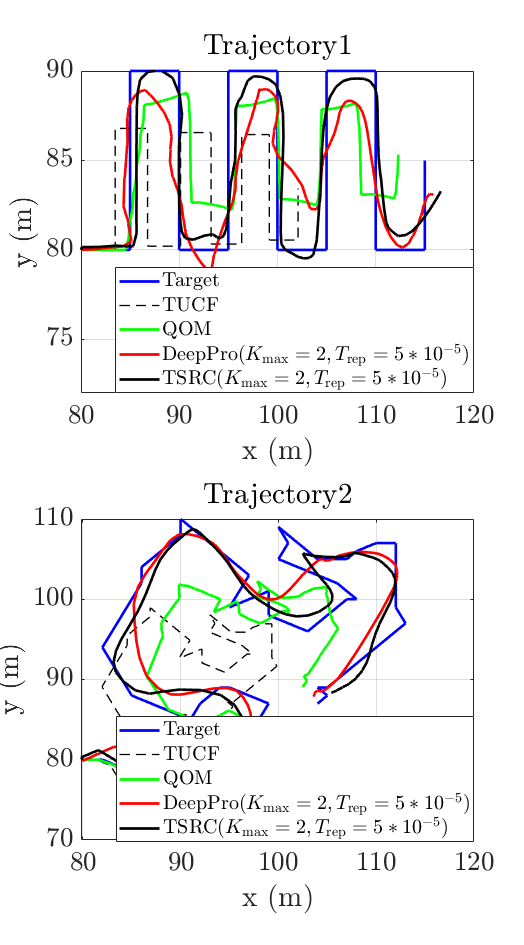
We compare different schemes (TUCF, VA-QOM, DeepPro, and TSRC) via simulation using two types of trajectories, as shown in Fig. 9. The first trajectory is a simple one but typical for our use case, while the second is more complex with a randomly generated trajectory. Fig. 9 (a) plots the trajectory comparison over different schemes. We can observe that the trajectory of the TUCF is notably most distant from the target trajectory. The TUCF and the VA-QOM share a similar trajectory shape because their generated C&C data is the same. However, the VA-QOM, with its ability to update target positions and prioritise the queue, achieves a trajectory closer to the target one compared to the TUCF. Due to the severe packet loss and delay, the update in the VA-QOM is always not on time, which still results in a huge gap between the trajectory of the VA-QOM and the target one. The DeepPro’s trajectory is closer to the target one than the VA-QOM because it can generate optimal C&C data via the DQN algorithm and decrease the risk of packet loss by the proactive repetition scheme. By integrating the DeepPro and the VA-QOM, the trajectory of our proposed TSRC framework is the closest to the target trajectory, indicating superior performance.
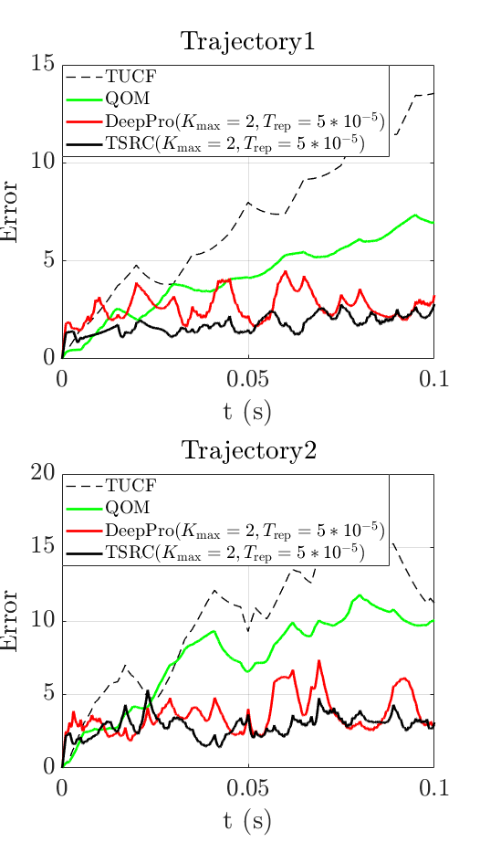
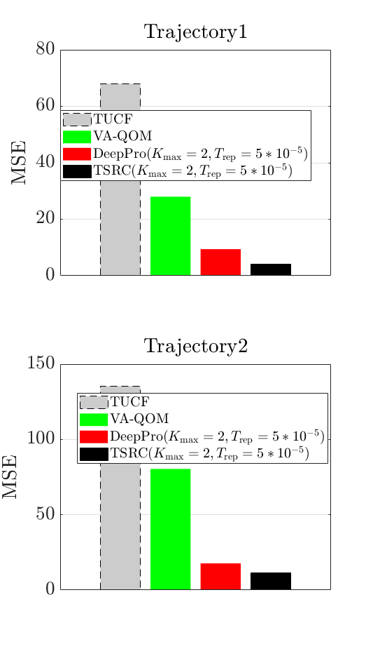
Fig. 9 (b) plots the error comparison for different schemes over time. It can be noticed that our proposed TSRC achieves the lowest overall error, with the DeepPro and VA-QOM also showing lower overall errors compared to TUCF. Interestingly, the error of the DeepPro and the TSRC remains stable over time, whereas the error of the TUCF and the VA-QOM fluctuate substantially over time. The reason is that the TUCF and VA-QOM are more sensitive to the communication environment with the same C&C data sequence, while the DeepPro and the TSRC can dynamically adapt their generated C&C data to the communication environment automatically. Fig. 9 (c) presents the MSE comparison over different schemes. The TUCF achieves the highest MSE. Compared to TUCF, both the DeepPro and VA-QOM substantially reduce MSE by 86.92 and 40.61, respectively. The TSRC, based on the integration of the DeepPro and VA-QOM, achieves the lowest MSE, resulting in a remarkable 91.51 reduction compared to TUCF.
Fig. 10 presents the impact of the proactive repetition scheme on the MSE for different schemes (TUCF, DeepPro, VA-QOM and TSRC).
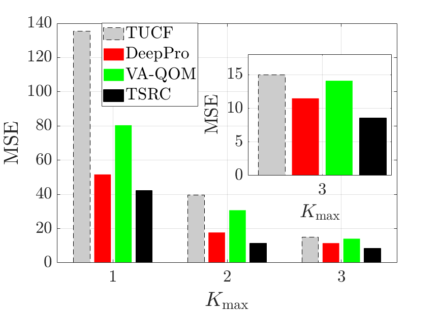
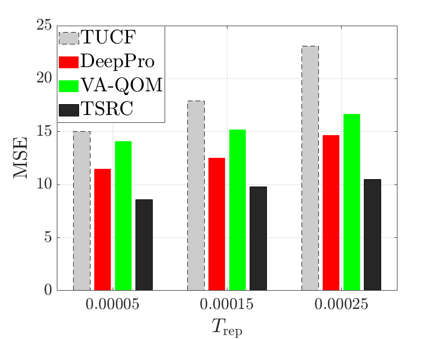
It is noticeable that our proposed TSRC scheme achieves the lowest MSE in various values of and , while the TUCF scheme has the highest MSE. Interestingly, the changes in and , which are highly related to the packet loss and delay of the C&C data, have a more obvious impact on the MSE of the TUCF and VA-QOM schemes compared to the DeepPro and TSRC. Since the DeepPro and TSRC are able to generate optimal C&C data to adapt to varying packet loss and delay conditions, their MSE remains more stable during such changes. Fig. 10 (a) plots the MSE for various schemes over different values of with a fixed . We can observe that increasing leads to a decrease in MSE for all schemes. This reduction is due to a decrease in packet loss of each C&C data as increases. Additionally, the MSE gap between the TUCF and DeepPro schemes diminishes because DQN is more likely to select the C&C data which is the same as the TUCF when is higher. Fig. 10 (b) shows the MSE for various schemes against different values of with a fixed . It can be observed that with the increasing, there is a rise in the MSE of all schemes. The reason is that with a larger , the BS needs more time to transmit the next repetition if there is no ACK back, which increases the average arrival time of each C&C data.
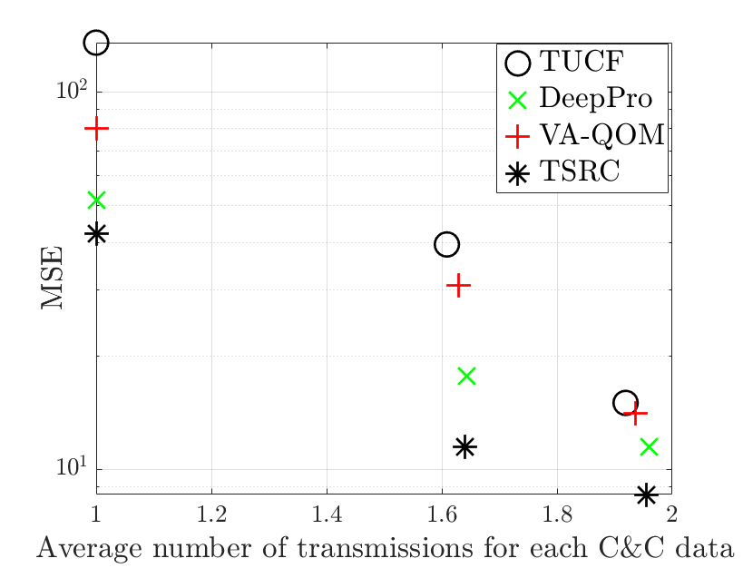
Fig. 11 plots the relationship between the MSE and the average number of actual transmissions for each C&C data over time of all schemes when with various . We can observe that as the average number of transmissions per C&C data increases, the MSE for all schemes decreases. Among all schemes, our proposed TSRC framework maintains the lowest MSE, while the TUCF exhibits the highest MSE when the average number of transmissions is nearly equivalent. This indicates that the design of the DeepPro and VA-QOM is able to enhance task performance, and the combination of them (TSRC) could significantly improve task performance while maintaining a similar number of transmissions. Moreover, we can see that our proposed TSRC framework requires fewer transmissions than the TUCF while achieving a comparable MSE, demonstrating its potential to reduce the number of transmissions while adhering to task performance constraints compared to the TUCF.
VI Conclusion
In this paper, we proposed task-oriented and semantics-aware communication in robotic control (TSRC) which incorporates both semantic-level and effectiveness-level for a real-time UAV waypoint transmission task. At the semantic level, we proposed the value of information (VoI) and the age of information (AoI) based queue ordering mechanism (VA-QOM) scheme at the UAV to rank the importance of data packets in the queue in accomplishing a task based on the AoI and the newly defined VoI. At the effectiveness level, we proposed a DeepPro scheme at the BS, which facilitates the generation of optimal control and command (C&)C data to accomplish the task and elevates the probability of successful transmission for each C&C data by optimizing the mean square error (MSE). Our simulation results shed light on that our proposed TSRC framework can decrease the number of average C&C data transmissions when maintaining a similar MSE and enhance the MSE when maintaining a similar number of C&C data transmissions.
References
- [1] Y. Liu, X. Ma, L. Shu, G. P. Hancke, and A. M. Abu-Mahfouz, “From Industry 4.0 to Agriculture 4.0: Current Status, Enabling Technologies, and Research Challenges,” IEEE Trans. Ind. Informatics, vol. 17, pp. 4322–4334, Jun. 2021.
- [2] A. Alam, “Educational Robotics and Computer Programming in Early Childhood Education: A Conceptual Framework for Assessing Elementary School Students’ Computational Thinking for Designing Powerful Educational Scenarios,” in Proc. 2022 Int. Conf. Smart Technologies Syst. Next Gener. Comput. (ICSTSN), pp. 1–7, Mar. 2022.
- [3] T. Haidegger, “Autonomy for Surgical Robots: Concepts and Paradigms,” IEEE Trans. Med. Robot. Bionics, vol. 1, pp. 65–76, Apr. 2019.
- [4] S. H. Alsamhi, O. Ma, and M. S. Ansari, “Convergence of Machine Learning and Robotics Communication in Collaborative Assembly: Mobility, Connectivity and Future Perspectives,” J. Intell. Robot. Syst., vol. 98, pp. 541–566, Oct. 2020.
- [5] Y. Zeng, R. Zhang, and T. J. Lim, “Wireless communications with unmanned aerial vehicles: opportunities and challenges,” IEEE Commun. Mag., vol. 54, pp. 36–42, May 2016.
- [6] M. Shafi, A. F. Molisch, P. J. Smith, T. Haustein, P. Zhu, P. De Silva, F. Tufvesson, A. Benjebbour, and G. Wunder, “5G: A Tutorial Overview of Standards, Trials, Challenges, Deployment, and Practice,” IEEE J. Sel. Areas Commun., vol. 35, pp. 1201–1221, Apr. 2017.
- [7] H. Ren, C. Pan, Y. Deng, M. Elkashlan, and A. Nallanathan, “Joint Power and Blocklength Optimization for URLLC in a Factory Automation Scenario,” IEEE Trans. Wireless Commun., vol. 19, pp. 1786–1801, Dec. 2020.
- [8] C. Pan, H. Ren, Y. Deng, M. Elkashlan, and A. Nallanathan, “Joint Blocklength and Location Optimization for URLLC-Enabled UAV Relay Systems,” IEEE Commun. Lett., vol. 23, pp. 498–501, Jan. 2019.
- [9] B. Chang, L. Zhang, L. Li, G. Zhao, and Z. Chen, “Optimizing Resource Allocation in URLLC for Real-Time Wireless Control Systems,” IEEE Trans. Veh. Technol., vol. 68, pp. 8916–8927, Jul. 2019.
- [10] “Minimum requirements related to technical performance for IMT-2020 radio interface(s),” tech. rep., doc. ITU-R M, Oct. 2016.
- [11] C. D. Alwis, A. Kalla, Q.-V. Pham, P. Kumar, K. Dev, W.-J. Hwang, and M. Liyanage, “Survey on 6G Frontiers: Trends, Applications, Requirements, Technologies and Future Research,” IEEE Open J. Commun. Soc., vol. 2, pp. 836–886, Apr. 2021.
- [12] J. Morales, G. Rodriguez, G. Huang, and D. Akopian, “Toward UAV Control via Cellular Networks: Delay Profiles, Delay Modeling, and a Case Study Within the 5-mile Range,” IEEE Trans. Aerosp. Electron. Syst., vol. 56, pp. 4132–4151, Apr. 2020.
- [13] G. Gui, M. Liu, F. Tang, N. Kato, and F. Adachi, “6G: Opening New Horizons for Integration of Comfort, Security, and Intelligence,” IEEE Wireless Commun., vol. 27, pp. 126–132, Mar. 2020.
- [14] “Framework and overall objectives of the future development of IMT for 2030 and beyond,” tech. rep., ITU-T Tech. Rep., Jun. 2023.
- [15] A. Ranjha, G. Kaddoum, and K. Dev, “Facilitating URLLC in UAV-Assisted Relay Systems With Multiple-Mobile Robots for 6G Networks: A Prospective of Agriculture 4.0,” IEEE Trans. Ind. Informatics, vol. 18, pp. 4954–4965, Nov. 2022.
- [16] S. Zhang, H. Zhang, and L. Song, “Beyond D2D: Full Dimension UAV-to-Everything Communications in 6G,” IEEE Trans. Veh. Technol., vol. 69, pp. 6592–6602, Apr. 2020.
- [17] W. Sun, H. Zhang, R. Wang, and Y. Zhang, “Reducing Offloading Latency for Digital Twin Edge Networks in 6G,” IEEE Trans. Veh. Technol., vol. 69, pp. 12240–12251, Aug. 2020.
- [18] T. Johannink, S. Bahl, A. Nair, J. Luo, A. Kumar, M. Loskyll, J. A. Ojea, E. Solowjow, and S. Levine, “Residual Reinforcement Learning for Robot Control,” in Proc. 2019 Int. Conf. Robotics Autom. (ICRA), pp. 6023–6029, May 2019.
- [19] C. Yang, D. Huang, W. He, and L. Cheng, “Neural Control of Robot Manipulators With Trajectory Tracking Constraints and Input Saturation,” IEEE Trans. Neural Netw. Learn. Syst., vol. 32, pp. 4231–4242, Aug. 2021.
- [20] P. Iyer, S. Tarekar, and S. Dixit, “Hand Gesture Controlled Robot,” in Proc. 2019 9th Int. Conf. Emerging Trends Eng. Technol. - Signal Inf. Process. (ICETET-SIP-19), pp. 1–5, Nov. 2019.
- [21] H. Zhou, X. Liu, Y. Deng, N. Pappas, and A. Nallanathan, “Task-Oriented and Semantics-Aware 6G Networks,” arXiv e-prints, p. arXiv:2210.09372, Oct. 2022.
- [22] M. Nasr-Azadani, J. Abouei, and K. N. Plataniotis, “Single- and Multiagent Actor-Critic for Initial UAV’s Deployment and 3-D Trajectory Design,” IEEE Internet Things J., vol. 9, pp. 15372–15389, Feb. 2022.
- [23] Z. Wang, R. Zhou, C. Hu, and Y. Zhu, “Online Iterative Learning Compensation Method Based on Model Prediction for Trajectory Tracking Control Systems,” IEEE Trans. Ind. Informatics, vol. 18, pp. 415–425, Jun. 2022.
- [24] Z. Meng, C. She, G. Zhao, and D. De Martini, “Sampling, Communication, and Prediction Co-Design for Synchronizing the Real-World Device and Digital Model in Metaverse,” IEEE J. Sel. Areas Commun., vol. 41, pp. 288–300, Nov. 2023.
- [25] X. Luo, H.-H. Chen, and Q. Guo, “Semantic Communications: Overview, Open Issues, and Future Research Directions,” IEEE Wireless Commun., vol. 29, pp. 210–219, Jan. 2022.
- [26] D. Gündüz, Z. Qin, I. E. Aguerri, H. S. Dhillon, Z. Yang, A. Yener, K. K. Wong, and C.-B. Chae, “Beyond Transmitting Bits: Context, Semantics, and Task-Oriented Communications,” IEEE J. Sel. Areas Commun., vol. 41, pp. 5–41, Nov. 2023.
- [27] H. Xie, Z. Qin, G. Y. Li, and B.-H. Juang, “Deep Learning Enabled Semantic Communication Systems,” IEEE Trans. Signal Process., vol. 69, pp. 2663–2675, Apr. 2021.
- [28] Z. Weng and Z. Qin, “Semantic Communication Systems for Speech Transmission,” IEEE J. Sel. Areas Commun., vol. 39, pp. 2434–2444, Jun. 2021.
- [29] M. Kountouris and N. Pappas, “Semantics-Empowered Communication for Networked Intelligent Systems,” IEEE Commun. Mag., vol. 59, pp. 96–102, Jun. 2021.
- [30] Z. Wang, Y. Deng, and A. H. Aghvami, “Task-oriented and Semantics-aware Communication Framework for Augmented Reality,” arXiv e-prints, p. arXiv:2306.15470, June 2023.
- [31] R. D. Yates, Y. Sun, D. R. Brown, S. K. Kaul, E. Modiano, and S. Ulukus, “Age of Information: An Introduction and Survey,” IEEE J. Sel. Areas Commun., vol. 39, pp. 1183–1210, Mar. 2021.
- [32] G. J. Stamatakis, N. Pappas, A. Fragkiadakis, and A. Traganitis, “Semantics-Aware Active Fault Detection in IoT,” in Proc. 2022 20th Int. Symp. Model. Optim. Mobile, Ad hoc, Wireless Networks (WiOpt), pp. 161–168, Sep. 2022.
- [33] W. Yang, H. Du, Z. Q. Liew, W. Y. B. Lim, Z. Xiong, D. Niyato, X. Chi, X. Shen, and C. Miao, “Semantic Communications for Future Internet: Fundamentals, Applications, and Challenges,” IEEE Commun. Surv. Tutorials, vol. 25, pp. 213–250, Nov. 2023.
- [34] A. Kosta, N. Pappas, A. Ephremides, and V. Angelakis, “Age and value of information: Non-linear age case,” in Proc. 2017 IEEE Int. Symp. Inf. Theory (ISIT), pp. 326–330, Jun. 2017.
- [35] E. Fountoulakis, N. Pappas, and M. Kountouris, “Goal-oriented Policies for Cost of Actuation Error Minimization in Wireless Autonomous Systems,” IEEE Commun. Lett., pp. 1–1, Jun. 2023.
- [36] D. Huang, F. Gao, X. Tao, Q. Du, and J. Lu, “Toward Semantic Communications: Deep Learning-Based Image Semantic Coding,” IEEE J. Sel. Areas Commun., vol. 41, pp. 55–71, Nov. 2023.
- [37] A. Gupta, P. Zhang, G. Lalwani, and M. Diab, “CASA-NLU: Context-Aware Self-Attentive Natural Language Understanding for Task-Oriented Chatbots,” arXiv e-prints, p. arXiv:1909.08705, Sept. 2019.
- [38] H. Sun, J. Bao, Y. Wu, and X. He, “Mars: Modeling context & state representations with contrastive learning for end-to-end task-oriented dialog,” in Findings of the Association for Computational Linguistics: ACL 2023 (A. Rogers, J. Boyd-Graber, and N. Okazaki, eds.), (Toronto, Canada), pp. 11139–11160, Association for Computational Linguistics, July 2023.
- [39] Y. Xu, H. Zhou, and Y. Deng, “Task-Oriented Semantics-Aware Communication for Wireless UAV Control and Command Transmission,” IEEE Commun. Lett., pp. 1–1, Jun. 2023.
- [40] Y. Liu, Y. Deng, M. Elkashlan, A. Nallanathan, and G. K. Karagiannidis, “Analyzing Grant-Free Access for URLLC Service,” IEEE J. Sel. Areas Commun., vol. 39, pp. 741–755, Aug. 2021.