Brain-Inspired Visual Odometry: Balancing Speed and Interpretability through a System of Systems Approach
Abstract
In this study, we address the critical challenge of balancing speed and accuracy while maintaining interpretablity in visual odometry (VO) systems, a pivotal aspect in the field of autonomous navigation and robotics. Traditional VO systems often face a trade-off between computational speed and the precision of pose estimation. To tackle this issue, we introduce an innovative system that synergistically combines traditional VO methods with a specifically tailored fully connected network (FCN). Our system is unique in its approach to handle each degree of freedom independently within the FCN, placing a strong emphasis on causal inference to enhance interpretability. This allows for a detailed and accurate assessment of relative pose error (RPE) across various degrees of freedom, providing a more comprehensive understanding of parameter variations and movement dynamics in different environments. Notably, our system demonstrates a remarkable improvement in processing speed without compromising accuracy. In certain scenarios, it achieves up to a 5% reduction in Root Mean Square Error (RMSE), showcasing its ability to effectively bridge the gap between speed and accuracy that has long been a limitation in VO research. This advancement represents a significant step forward in developing more efficient and reliable VO systems, with wide-ranging applications in real-time navigation and robotic systems.
I Introduction
A ”system of systems” is the principle that governs the operation of the human brain. Each of these subsystems caters to a specific function. A diverse range of cognitive capabilities is orchestrated by them when they work together in synchrony. This process is evident in odometry, which processes spatial navigation and movement. In order for this skill to emerge, key areas like the hippocampus, entorhinal cortex, and vestibular nucleus must work together. As a result, we are able to decipher distance, direction, and motion, which strengthens our intrinsic navigation skills [1, 2].
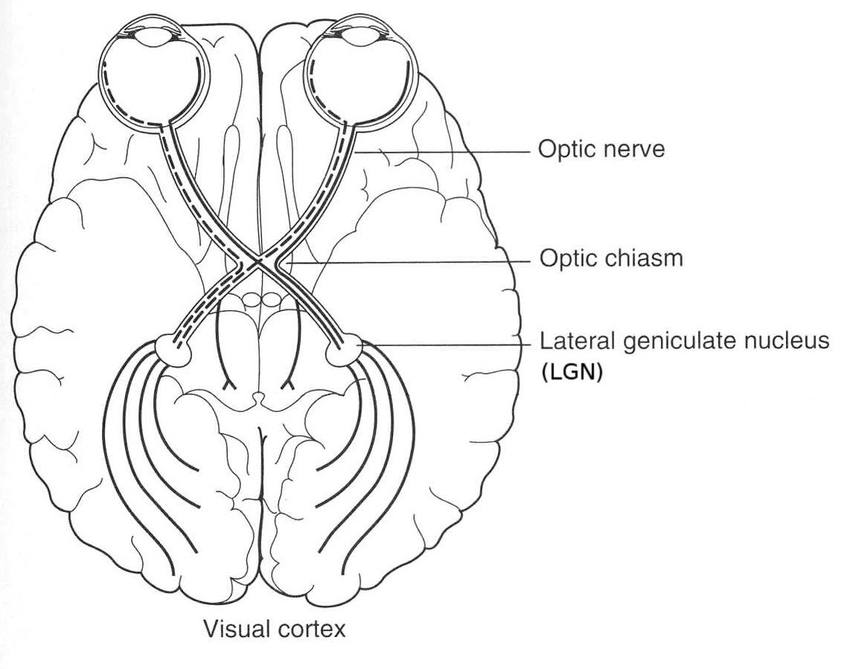
From the retina in the eye, the optic nerve transmits visual information to the brain.[4]
A data routing element is evident in the optical chiasm. At the optic chiasm, the optic nerves from each eye cross. In this way, the visual field from each eye is appropriately divided between the left and right hemispheres of the brain. [4]
The Lateral Geniculate Nucleus (LGN) is a relay station in the thalamus that processes visual signals before they reach the visual cortex. It can be viewed as a preprocessing unit that optimizes and filters visual data in preparation for higher-level processing.[4]
It can be compared to the CPU of the visual system, or the main processing unit. As we perceive our visual environment, the visual cortex interprets the processed signals from the LGN, located in the occipital lobe.[5]
A ”system of systems” can be seen in this interconnected flow from the optic nerve, through the optic chiasm, and LGN, and finally to the visual cortex. Each component performs a specific function, but works together to achieve the overarching goal of vision. The brain exemplifies the intricate interplay and coordination seen in complex systems elsewhere.
The brain’s system of systems is resilient, and can continue to work even when one system isn’t working properly. In our model, a fully connected network receives poses derived from traditional visual odometry, but provides resiliency so that either system can be changed without affecting the other. In other approaches, such as Rovio[6, 7], even a small delay or noisy data from a sensor or a computation module can compromise the whole system.
Our fully-connected neural network infers from fewer parameters than convolutional neural network approaches, which often require multiple frames for inference. The raw pose features obtained from traditional visual odometry are a sufficient basis for inference in our model.
In this work, we introduce Timestamped Explainable AI. Utilizing cognitive robotics and innovative AI techniques, this methodology enhances visual odometry’s speed and interpretability by combining deep learning and traditional visual odometry. Additionally, we can strike a delicate balance between precision and interpretability at speeds ranging from 35 to 64 frames per second.
Our brain-inspired ”system of systems” is based on three systems. The first is the ground truth transformation, which assists in the training process by making each movement independent of previous ones. The other two are traditional visual odometry and our deep learning approach, which are involved in training and testing. Our results demonstrate the model’s interpretability, speed and precision.
II Related Work
Research has been motivated by the complexity and efficiency of the human brain to develop models that mimic its ”system of systems” structure [8]. Through its modular and interconnected architecture, the human brain has paved the way for advances in robotics and computer vision by enabling it to process vast amounts of information rapidly and accurately. In the vast expanse of cognitive robotics and artificial intelligence research, our endeavor stands as a testament to the power of drawing inspiration from nature’s most complex creation: the human brain [9].
When viewed through the lens of the brain’s ”system of systems” structure, we have developed a visual odometry approach that is both efficient and interpretable. The brain’s sophisticated network of interconnected “system of systems” [10] provides a perspective that helps unravel the multi-faceted complexities and interconnectedness foundational to our cognitive processes [11].
Venturing deeper into visual processing, the retina’s indispensable role shines through. The ganglion cells’ axons converge to form the optic nerve, predominantly connecting to the thalamus, especially the lateral geniculate nucleus (LGN), and the superior colliculus. The LGN stands as a pivotal relay, ensuring the retina’s visual information seamlessly reaches the cortex [2].
Interpretability and explainability are fundamental to deep learning [12]. The former looks at the consequences of tweaking parameters, while the latter traces the causes of AI decisions. The integration of these ideals with visual odometry presents some challenges From navigating the intricate web of modern VO systems to understanding the limitations of traditional methodologies, there are both opportunities and challenges.
By using visual odometry, a camera’s position can be estimated. Using subsequent frames, the camera’s orientation and position are calculated. After collecting a sequence of images from the camera, motion is calculated based on a reference frame to estimate the camera’s position. A feature is identified and matched between successive images to accomplish this. Robots can use odometry to determine their position and orientation without depending on external sensors, making it an important tool in robotics and computer vision[13, 14, 15].
We are developing a system for monocular visual odometry in this research. Several factors influenced our decision. It is true that integrating IMUs or GPS can provide additional information, but it also introduces additional error sources and complexities in system design and calibration [6, 7, 16, 17]. It is our goal to create a method for monocular visual odometry that is both computationally efficient and easy to interpret.
A feature-based method, ORB-SLAM, keeps track of the camera pose by detecting features in the images. Detecting features can be challenging in areas with low-contrast textures and dynamic objects. ORB-SLAM overcomes this problem by using a variety of techniques, including feature matching, key frame selection, and loop detection. As a result of these methods, the system is able to accurately determine the camera’s pose in challenging environments. Furthermore, the system is capable of detecting loop closure, which allows it to accurately determine the trajectory of the camera. [18, 19]
The disadvantage of ORB-SLAM is that it can be computationally expensive, since it requires a large number of feature points to be detected to accurately calculate the camera’s pose [20]. Additionally, since the system relies on feature detection, errors can occur if the features are not correctly identified. Inaccurate results can compromise the accuracy of the visual odometry [21].
DSO (Direct Sparse Odometry) is a direct method for estimating the 6-DoF camera pose[22]. Instead of detecting features, it focuses on the raw intensity of the images, as opposed to traditional feature-based methods. This method involves taking two images of a scene and calculating the camera’s relative 3D motion. In mobile applications and robotics, DSO is a real-time algorithm that runs on a single processor. Due to its robustness to motion blur, this algorithm does not require prior knowledge of the scene. The main disadvantage of DSO is that it is sensitive to lighting conditions, so it is not suitable for low-light environments. In addition, it is less reliable when dealing with fast motion and high-frequency textures.
As a lightweight method, MonoVO is computationally efficient. Because of this, it is fast, but it can also result in lower accuracy than methods that require more computational resources. Because MonoVO uses an inverse depth parameterization for camera motion, it is able to achieve this efficiency more easily than other representations. The limited resolution of the parameterization, however, can also reduce the accuracy of the estimates[23].
Visual odometry has benefited greatly from deep learning methods in recent years [24]. The underlying features of the task have been learned using deep learning methods to achieve better results than traditional approaches. Deep learning methods can improve visual odometry accuracy, speed, and generalization[25]. A deep learning model can also be used to gain a deeper understanding of a scene’s underlying dynamics in addition to predicting future motion. As a result of this prediction, the hardware will be burdened with additional complexity [26, 27].
A recent trend in visual odometry is the integration of deep learning techniques [28]. Sequence handling can be accomplished with LSTMs without having to store entire image series [29]. In addition, these approaches require a high level of training and suffer from cumulative errors As a result, they are not suitable for practical, large-scale applications[30, 31].
Our novel approach combines deep learning and traditional visual odometry techniques as separate systems and focuses on speed and accuracy. Using visual odometry in our deep neural network enhances interpretability by breaking down the model into individual degrees of freedom.
Since last moves have no effect on estimating pose in current moves, our model is robust even in scenarios with fast or abrupt movements. Our goal is to surpass the limitations of current visual odometry models by eschewing the LSTM approach and focusing on a fast and interpretable model, thus advancing robotics and autonomous navigation.
III Technical Description
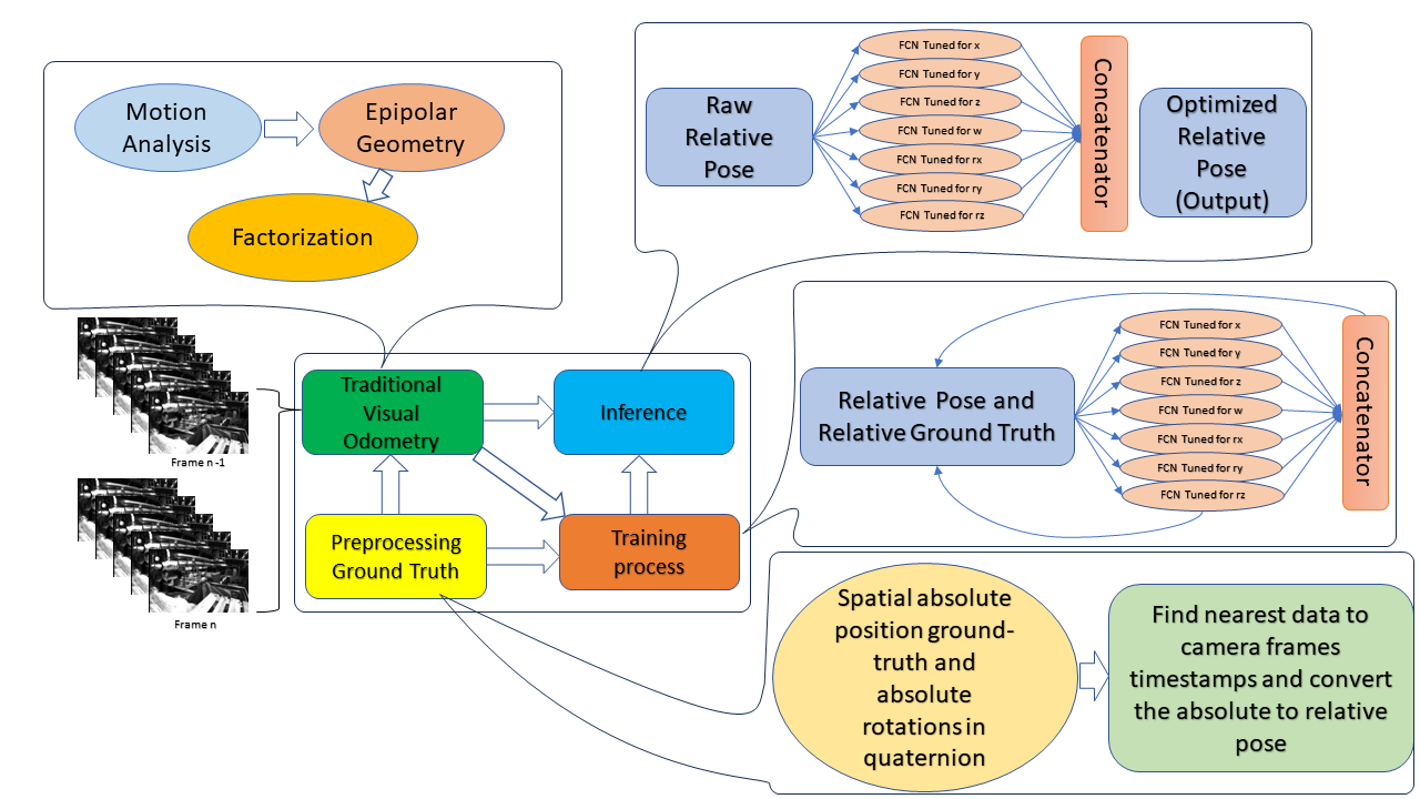
We aim to develop a platform that is easy to understand and fast by taking inspiration from the way the brain’s distinct regions work together harmoniously for faster performance. The system is divided into three subsystems: ground truth data transformation, visual odometry, and deep learning. By increasing visual odometry’s modularity and deep learning’s robustness, we are able to mimic the brain’s complex ”system of systems.”
Figure 2 depicts the system of systems, capturing not only the essence of traditional visual odometry, but also the flexibility of our deep neural network. We intentionally left our platform’s design customizable, emphasizing the importance of adaptability in response to varying inputs, similar to the adaptability of the brain. Yet, comprehensive details of the fully connected networks used in our experiments are available.
To interpret raw movements, our traditional visual odometry subsystem employs sparse optical flow, which is analogous to the brain’s spatial processing. Our neural network subsystem relies on these movements, harmonized with the adjusted ground truth for each frame pair.
We have crafted a machine learning platform that emphasizes modularity, interpretability, and adaptability by embracing the brain’s ”System of Systems” architecture.
With sparse optical flow, we capture raw movements using traditional visual odometry. Our neural network uses these movements as variables, along with the adjusted ground truth generated for each pair of frames.
III-A Ground-truth transformation
We didn’t use absolute frames since we didn’t want to be dependent on the last move. As a result, we would not have to use an LSTM or another reinforcement technique and the hardware would not be burdened as much and the complexity would be reduced.
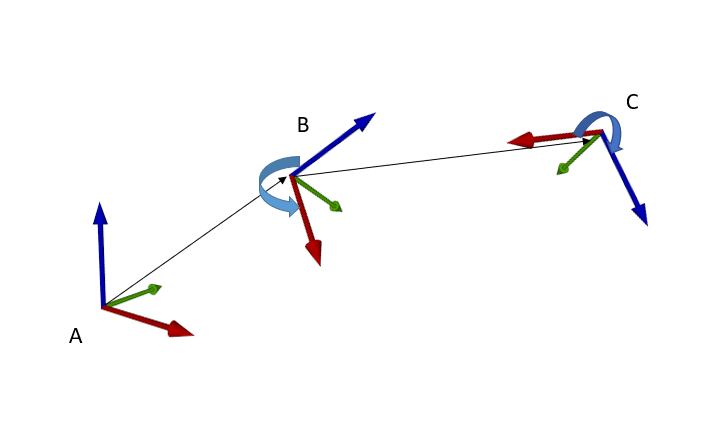
When evaluating movements, we emphasize relative frames over absolute frames. A global coordinate system defines an absolute frame as the camera’s position and orientation. Alternatively, a relative frame refers to the camera’s position and orientation as compared to its previous position.
When rotated or translated, each movement occupies a new space (see Figure 3).
It is necessary to factor in a transformation for each movement, which encompasses both rotation and translation matrices [33, 34, 35].
We consider rotation and translation matrices whenever we perform a movement:
In this matrix, signifies a rotation in the Special Orthogonal Group (SO(3)), while t is a column vector in . The motion of a rigid body can be depicted by a set of all 4x4 real matrices, known as the Special Euclidean group (SE(3)). The element in SE(3) can be portrayed as the pair .
In order to determine the elements of the inverse transformation matrix, we multiply a matrix with its inverse, as demonstrated below:
We can see that:
Bearing these considerations in mind, we’ve been able to transform the ground truth from absolute rotation and translation to relative rotation and translation.
III-B Traditional Visual Odometry
As we endeavor to replicate the brain’s ”system of systems” architecture, we recognize that each subsystem must function efficiently in order to ensure that the overall system runs efficiently. Similarly, our Traditional Visual Odometry subsystem is optimized for maximum speed and efficiency, just as the brain is capable of handling vast amounts of data quickly.
We use sparse optical flow to derive the essential matrix linking corresponding points between two images. In low-texture environments, this method can track a select set of points over time. With fewer points being monitored, the processing speed is amplified and no calibration or high-end cameras are required to process images. Essentially, this ensures that our Visual Odometry will not become a bottleneck, providing the necessary pace to the overarching system.
In order to detect corners precisely, we utilize the Harris technique [32], while the Shi-Tomasi [36] down-sampling approach for patches ensures robustness against noisy images. Singular value decomposition is used to extract rotation and translation matrices for our pose recovery strategy.
In our design, Traditional Visual Odometry is principally used to provide insight into the transformation between two consecutive frames instead of a key frames. Because there are more frames in each second, even if we have an extreme error in two frames, the mean of the relative pose error will be reduced.
III-C Deep Learning Approach
We have developed an innovative deep learning approach that aligns with the brain’s modular functionality by drawing inspiration from its ”system of systems” architecture. Several distinct regions of the brain are dedicated to specialized tasks, illustrating the importance of optimizing subsystems for precise functionality. We also fine-tune every degree of freedom individually to ensure that each component is optimized to its maximum potential.
As a result of the inherent differences in movement patterns, such as stark rotations around the and axes compared to the more stable rotations around the axis, we have opted for a Fully Connected Network (FCN) over the more commonly adopted Convolutional Neural Network (CNN). Since the FCN does not process entire images, it promises a faster processing speed due to its fewer parameters. We made this choice in order to ensure that our approach remains swift and efficient, reflecting how individual brain subsystems contribute to the overall efficiency and speed of cognitive processes.
As each degree of freedom is trained independently, we are able to perform a granular analysis, so that we can determine if each pre-trained neural network branch is compatible with movement patterns, and determine whether a different architectural approach is required.
When compared with end-to-end analyses, this modular approach not only enables a custom-tailored model for each movement and degree of freedom, but also offers a holistic perspective. We are able to gain a deeper understanding of both absolute trajectory and relative pose by enhancing the interpretability of our model.
The modularity and customization of our activation functions, including Relu, Leaky-Relu, Elu, Tanh, and Sigmoid, demonstrates our commitment to modularity and customization. Based on the specific requirements, we can target either global error reduction (absolute trajectory errors - ATE) or local error reduction (relative pose errors - RPE), as shown in table I.
To describe this mathematically, let’s denote each degree of freedom as , where and is the total number of degrees of freedom. The model for each degree of freedom can be represented as . Rather than learning a combined model jointly, we optimize each individually and then combine them into an integrated model. This can be formulated as:
| (1) |
By optimizing each separately, we can examine the contribution of each degree of freedom to the overall motion in a more detailed way, thus obtaining a more accurate model. This process results in greater transparency and comprehension of the underlying movements and poses. The comparison with the end-to-end approach, as shown in table I, validates that our method provides a more precise understanding of the influence of each degree of freedom. A model based on individual optimization can be used to examine in depth how each degree of freedom contributes to overall motion, resulting in a more accurate and transparent model. Comparing our method with the end-to-end approach, as presented in table I, further reinforces the precision and understanding we provide regarding the influence of each degree of freedom.
At the end we used pretrained branches and as we can see in Figure 2, we used inception to get better result for the traine model. In other words, we used different modules based on our customized desired result for less Relative Pose Error.
IV Experimental Results
In our research, we have merged traditional visual odometry techniques with an analytical method for pinpointing and tracking points of interest through patch similarity. This synergy was anticipated to yield a fast and efficient method, particularly valuable for low-performance embedded devices, a notable contribution of our study.
Remarkably, each processing step in our system requires only 15.625 to 31.25 microseconds in our modest test environment. When applied in real-world scenarios on a standard Core i7 laptop, this efficiency translates into an exceptional frame rate, enabling real-time or even accelerated processing, as we demonstrate.
Our method’s pipelined structure also led us to test the essential matrix in addition to the fundamental matrix within the epipolar geometry framework. The results averaged out to show no significant disparity in speed or precision between the two. However, the essential matrix mode, utilizing specifications from the right camera of the EuRoC dataset [37], exhibited about 0.1 meters less error compared to the traditional odometry mode. This error margin diminished even further when augmented with our fully connected neural network.
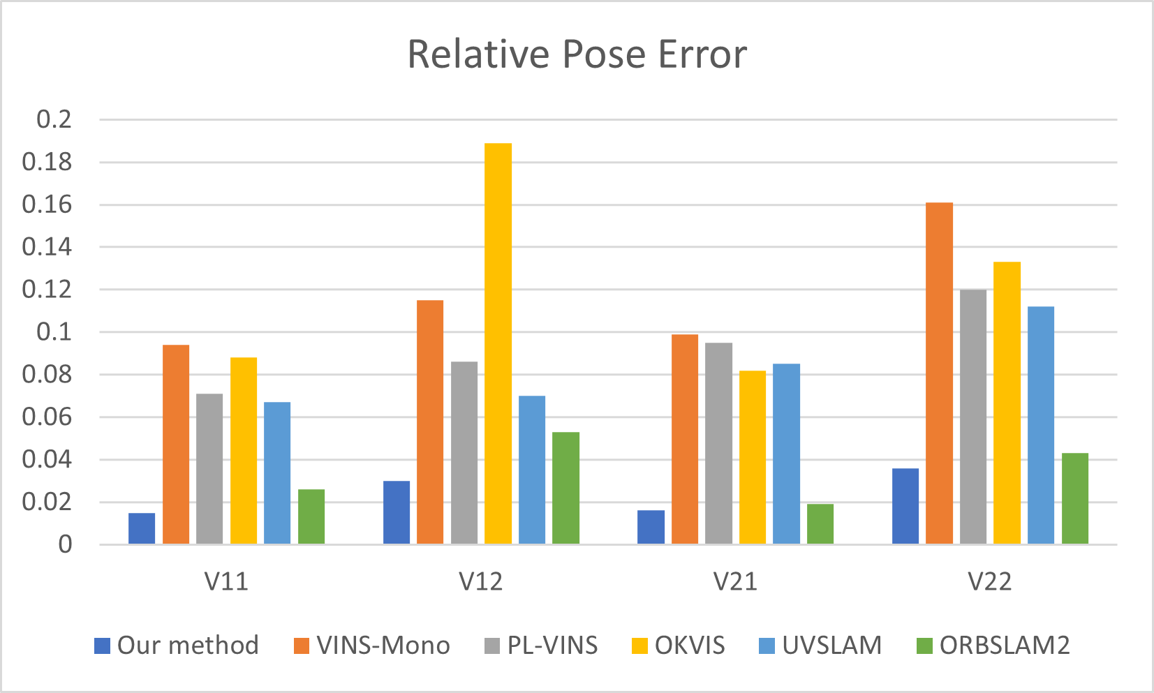
Further experiments conducted with the EuRoC MAV dataset [37] underscored our approach’s superiority. As depicted in Figure 4, our method consistently outperformed various contemporary counterparts, including those integrating inertia as an observer [38, 39]. These results affirm our method’s ability to maintain or surpass accuracy while significantly enhancing computation speed.
Our approach’s decomposition into smaller subproblems facilitated more manageable training and optimization phases. This modular design allowed for the independent training of different components, such as the feature extractor and the pose estimator. Such decomposition enabled training on extensive datasets, which would have been impractical with a singular, monolithic model.
Using this refined method, we achieved state-of-the-art results on the EuRoC dataset [37]. Particularly notable was an Absolute Trajectory Error (ATE) of 0.0149 on the V11 sequence, as shown in Table II. The efficacy of our modular architecture and decomposition strategy was evident in these results, detailed in Table I.
| Activation | RPE Trans. X | RPE Trans. Y | RPE Trans. Z | RPE Trans. | RPE Rot. RX | RPE Rot. RY | RPE Rot. RZ |
|---|---|---|---|---|---|---|---|
| Leaky ReLU | 2.0151 | 1.0233 | 2.2991 | 1. | 0.6825 | 0.5212 | 0.6468 |
| SELU | 2.2198 | 1.3453 | 1.7351 | 1.8026 | 0.4322 | 0.4109 | 0.7000 |
| Tanh | 1.2642 | 1.4221 | 1.4629 | 1.3857 | 0.6186 | 0.7383 | 0.6360 |
| ReLU | 3.4905 | 2.8742 | 3.2816 | 3.2256 | 0.4187 | 0.3926 | 0.6707 |
| Sigmoid | 1.6106 | 1.5485 | 2.0732 | 1.7598 | 0.6321 | 0.3583 | 0.6258 |
| Activation | ATE Trans. X | ATE Trans. Y | ATE Trans. Z | Mean ATE |
|---|---|---|---|---|
| Leaky ReLU | 2.0151 | 1.0233 | 2.2991 | 1.7792 |
| SELU | 2.2198 | 1.3453 | 1.7351 | 1.7667 |
| Tanh | 1.2642 | 1.4221 | 1.4629 | 1.3831 |
| ReLU | 3.4905 | 2.8742 | 3.2816 | 3.2154 |
| Sigmoid | 1.6106 | 1.5485 | 2.0732 | 1.7441 |
The optimization of activation functions based on specific task requirements was another aspect of our research. This exploration demonstrated that different activation functions can influence model performance variably, contributing to both the model’s speed and interpretability.
In conclusion, our findings illustrate that visual odometry (VO) models can achieve both interpretability and speed through a well-crafted, brain-inspired hybrid approach. Our system, with processing speeds ranging between 15.625 to 31.25 microseconds and high frame rates on standard computing hardware, sets a new benchmark in the field. It heralds a future where speed, accuracy, and transparency in VO models coexist harmoniously.
V Conclusion
Our endeavor stands as a testament to the power of drawing inspiration from nature’s most complex creation: the human brain, in the vast expanse of cognitive robotics and artificial intelligence research. We have developed a visual odometry approach that is both efficient and interpretable when viewed through the lens of the brain’s ”System of Systems” structure.
We combine traditional visual odometry techniques with the capabilities of a fully connected network, embodying the modularity and interconnectedness of neural systems. Through this fusion, we have developed a methodology that is not only explainable but also demonstrates remarkable performance metrics. We believe that our approach will be valuable in real-world applications, particularly because of the speed enhancements achieved by our system, clocking impressive frame rates on standard hardware.
In addition, our modular method ensures a level of granularity and clarity in the results that is often lacking in contemporary research due to the fact that each degree of freedom is treated individually. In our experiments, we have consistently outperformed several benchmarks, further demonstrating the efficacy of our approach.
In essence, we have paved a way for future research in this area by combining cognitive robotics with cutting-edge artificial intelligence techniques. As a result of our work, we believe that future endeavors will be guided towards a harmonious blend of speed, accuracy, and interpretability. As we move further into the era of artificial intelligence, our research emphasizes the profound potential in looking back to nature for inspiration, ensuring a future in which machines function with a precision and transparency reminiscent of human thinking.
References
- [1] M. B. Wall and A. T. Smith, “The representation of egomotion in the human brain,” Current biology, vol. 18, no. 3, pp. 191–194, 2008.
- [2] M. Hitier, S. Besnard, and P. F. Smith, “Vestibular pathways involved in cognition,” Frontiers in integrative neuroscience, vol. 8, p. 59, 2014.
- [3] J. Eichhorn, “Applications of kernel machines to structured data,” 2007.
- [4] C. G. De Moraes, “Anatomy of the visual pathways,” Journal of glaucoma, vol. 22, pp. S2–S7, 2013.
- [5] S. Jacobson, E. M. Marcus, S. Pugsley, S. Jacobson, E. M. Marcus, and S. Pugsley, “Visual system and occipital lobe,” Neuroanatomy for the Neuroscientist, pp. 445–476, 2018.
- [6] M. Bloesch, S. Omari, M. Hutter, and R. Siegwart, “Robust visual inertial odometry using a direct ekf-based approach,” in Intelligent Robots and Systems (IROS), 2015 IEEE/RSJ International Conference on, pp. 298–304, IEEE, 2015.
- [7] M. Bloesch, M. Burri, S. Omari, M. Hutter, and R. Siegwart, “Iterated extended kalman filter based visual-inertial odometry using direct photometric feedback,” The International Journal of Robotics Research, vol. 36, no. 10, pp. 1053–1072, 2017.
- [8] M. Jamshidi, “Introduction to system of systems,” in Systems of Systems Engineering, pp. 1–36, CRC Press, 2017.
- [9] D. Berco and D. Shenp Ang, “Recent progress in synaptic devices paving the way toward an artificial cogni-retina for bionic and machine vision,” Advanced Intelligent Systems, vol. 1, no. 1, p. 1900003, 2019.
- [10] R. M. Ruehl, V. L. Flanagin, L. Ophey, T. M. Raiser, K. Seiderer, M. Ertl, J. Conrad, and P. Zu Eulenburg, “The human egomotion network,” NeuroImage, vol. 264, p. 119715, 2022.
- [11] C. Axenie and J. Conradt, “Cortically inspired sensor fusion network for mobile robot egomotion estimation,” Robotics and Autonomous Systems, vol. 71, pp. 69–82, 2015.
- [12] L. H. Gilpin, D. Bau, B. Z. Yuan, A. Bajwa, M. Specter, and L. Kagal, “Explaining explanations: An overview of interpretability of machine learning,” in 2018 IEEE 5th International Conference on data science and advanced analytics (DSAA), pp. 80–89, IEEE, 2018.
- [13] C. Cadena, L. Carlone, H. Carrillo, Y. Latif, D. Scaramuzza, J. Neira, I. Reid, and J. J. Leonard, “Past, present, and future of simultaneous localization and mapping: Toward the robust-perception age,” IEEE Transactions on Robotics, vol. 32, no. 6, pp. 1309–1332, 2016.
- [14] A. S. Huang, A. Bachrach, P. Henry, M. Krainin, D. Maturana, D. Fox, and N. Roy, “Visual odometry and mapping for autonomous flight using an rgb-d camera,” in Robotics Research, pp. 235–252, Springer, 2017.
- [15] R. Valencia and J. Andrade-Cetto, Mapping, planning and exploration with Pose SLAM. Springer, 2018.
- [16] P. Gui, L. Tang, and S. Mukhopadhyay, “Mems based imu for tilting measurement: Comparison of complementary and kalman filter based data fusion,” in Industrial Electronics and Applications (ICIEA), 2015 IEEE 10th Conference on, pp. 2004–2009, IEEE, 2015.
- [17] M. Maimone, Y. Cheng, and L. Matthies, “Two years of visual odometry on the mars exploration rovers,” Journal of Field Robotics, vol. 24, no. 3, pp. 169–186, 2007.
- [18] R. Mur-Artal, J. M. M. Montiel, and J. D. Tardos, “Orb-slam: a versatile and accurate monocular slam system,” IEEE Transactions on Robotics, vol. 31, no. 5, pp. 1147–1163, 2015.
- [19] R. Mur-Artal and J. D. Tardós, “Orb-slam2: An open-source slam system for monocular, stereo, and rgb-d cameras,” IEEE Transactions on Robotics, vol. 33, no. 5, pp. 1255–1262, 2017.
- [20] R. Mur-Artal, J. M. M. Montiel, and J. D. Tardos, “Orb-slam: a versatile and accurate monocular slam system,” IEEE transactions on robotics, vol. 31, no. 5, pp. 1147–1163, 2015.
- [21] Y. Yang, D. Tang, D. Wang, W. Song, J. Wang, and M. Fu, “Multi-camera visual slam for off-road navigation,” Robotics and Autonomous Systems, vol. 128, p. 103505, 2020.
- [22] J. Engel, V. Koltun, and D. Cremers, “Direct sparse odometry,” IEEE transactions on pattern analysis and machine intelligence, vol. 40, no. 3, pp. 611–625, 2018.
- [23] J. Delmerico and D. Scaramuzza, “A benchmark comparison of monocular visual-inertial odometry algorithms for flying robots,” in 2018 IEEE international conference on robotics and automation (ICRA), pp. 2502–2509, IEEE, 2018.
- [24] S. Wang, R. Clark, H. Wen, and N. Trigoni, “Deepvo: Towards end-to-end visual odometry with deep recurrent convolutional neural networks,” in 2017 IEEE international conference on robotics and automation (ICRA), pp. 2043–2050, IEEE, 2017.
- [25] P. Muller and A. Savakis, “Flowdometry: An optical flow and deep learning based approach to visual odometry,” in 2017 IEEE Winter Conference on Applications of Computer Vision (WACV), pp. 624–631, IEEE, 2017.
- [26] M. R. U. Saputra, A. Markham, and N. Trigoni, “Visual slam and structure from motion in dynamic environments: A survey,” ACM Computing Surveys (CSUR), vol. 51, no. 2, pp. 1–36, 2018.
- [27] M. He, C. Zhu, Q. Huang, B. Ren, and J. Liu, “A review of monocular visual odometry,” The Visual Computer, vol. 36, no. 5, pp. 1053–1065, 2020.
- [28] T. Pandey, D. Pena, J. Byrne, and D. Moloney, “Leveraging deep learning for visual odometry using optical flow,” Sensors, vol. 21, no. 4, p. 1313, 2021.
- [29] R. Zhu, M. Yang, W. Liu, R. Song, B. Yan, and Z. Xiao, “Deepavo: Efficient pose refining with feature distilling for deep visual odometry,” Neurocomputing, vol. 467, pp. 22–35, 2022.
- [30] F. Xue, X. Wang, S. Li, Q. Wang, J. Wang, and H. Zha, “Beyond tracking: Selecting memory and refining poses for deep visual odometry,” in Proceedings of the IEEE/CVF Conference on Computer Vision and Pattern Recognition, pp. 8575–8583, 2019.
- [31] Z. Chen, H. Du, X. Xuecheng, R. Xiong, Y. Liao, and Y. Wang, “Learning interpretable bev based vio without deep neural networks,” in Conference on Robot Learning, pp. 1289–1298, PMLR, 2023.
- [32] C. G. Harris, M. Stephens, et al., “A combined corner and edge detector.,” in Alvey vision conference, vol. 15, pp. 10–5244, Citeseer, 1988.
- [33] C. Frank, Modern Robotics-Mechanics, Planning, and Control. Cambridge University Press, 2017.
- [34] R. M. Murray, Z. Li, and S. S. Sastry, A mathematical introduction to robotic manipulation. CRC press, 2017.
- [35] C.-T. Cao, V.-P. Do, and B.-R. Lee, “A novel indirect calibration approach for robot positioning error compensation based on neural network and hand-eye vision,” Applied Sciences, vol. 9, no. 9, p. 1940, 2019.
- [36] J. Shi and C. Tomasi, “Good features to track,” tech. rep., Cornell University, 1993.
- [37] M. Burri, J. Nikolic, P. Gohl, T. Schneider, J. Rehder, S. Omari, M. W. Achtelik, and R. Siegwart, “The euroc micro aerial vehicle datasets,” The International Journal of Robotics Research, vol. 35, no. 10, pp. 1157–1163, 2016.
- [38] C. Chen, H. Zhu, L. Wang, and Y. Liu, “A stereo visual-inertial slam approach for indoor mobile robots in unknown environments without occlusions,” IEEE Access, vol. 7, pp. 185408–185421, 2019.
- [39] H. Lim, J. Jeon, and H. Myung, “Uv-slam: Unconstrained line-based slam using vanishing points for structural mapping,” IEEE Robotics and Automation Letters, vol. 7, no. 2, pp. 1518–1525, 2022.