Performance of the Full-equipped Spin Flip Chopper For Neutron Lifetime Experiment at J-PARC
Abstract
To solve the “neutron lifetime puzzle,” where measured neutron lifetimes differ depending on the measurement methods, an experiment with pulsed neutron beam at J-PARC is in progress. In this experiment, neutrons are bunched into 40-cm lengths using a spin flip chopper (SFC), where the statistical sensitivity was limited by the aperture size of the SFC. The SFC comprises three sets of magnetic supermirrors and two resonant spin flippers. In this paper, we discuss an upgrade to enlarge the apertures of the SFC. The improved SFC achieved a signal-to-noise ratio of 250–400, which is comparable to the previous one. The statistics per unit time of the neutron lifetime experiment increased 2.8 times with the upgrade. Consequently, the time required to reach an accuracy of 1 s in the neutron lifetime experiment was reduced from 590 to 170 days, which is a significant reduction in time. This improvement in statistical accuracy will also contribute to the reduction of systematic uncertainties, such as background evaluation, fostering further advancements in the neutron lifetime experiments at J-PARC.
I INTRODUCTION
A neutron transforms into a proton, electron, and antineutrino through decay. The decay lifetime is an essential parameter in cosmology and particle physics. For instance, light elements in the universe were formed through big-bang nucleosynthesis (BBN), and the comparison of observations with theoretical predictions of element abundances offers a valuable opportunity to verify cosmological models. The neutron lifetime determines the proton-to-neutron ratio at the onset of the BBN, thereby influencing the yield of light elements, particularly 4He [1]. In a standard particle physics model, neutron lifetime is described by the matrix element of the Cabibbo-Kobayashi-Maskawa matrix. Here, can be used to determine the neutron lifetime and the ratio of the axial vector to vector coupling constant [2]. Moreover, the neutron lifetime is required for calculating the cross-section of the inverse reaction of neutron decay, which is an antineutrino capture by protons [3].
The neutron lifetime is measured using two methods. The first is the beam method, wherein the number of incoming neutrons and decays per unit time are counted. The second is the bottle method, wherein neutrons are confined in a container, and their missing over time is observed to derive their lifetime. While the accuracy of the former measurement is 2 s and that of the latter reaches subseconds, the average values of both methods differ, with a discrepancy of 9.5 s (4.6) [2]. Whether this discrepancy results from an error in the experiment or indicates an unknown phenomenon remains unresolved. Thus, experiments that are qualitatively different from previous ones, particularly beam methods that have not yet achieved high precision, are eagerly awaited.
To solve this problem, a different experiment using pulsed neutrons is currently underway at J-PARC [4]. This experiment is classified as a beam method. In contrast to previous beam experiments that detected protons from neutron decay, this new approach detects both neutrons and electrons from decay using the same detector. Because the observed particles are different, any oversight in the previous proton measurements should not affect this method.
The experiment is being conducted at the Materials and Life Science Experimental Facility (MLF) of J-PARC on the Fundamental Physics Beamline (BL05/NOP) [5, 6]. Neutrons are introduced into a 1-m-long gas detector (time projection chamber, TPC) after shaping into bunches with a length of 40 cm so that being fully contained inside the detector. Considering the data only when the neutron bunch is completely inside the TPC, the detector can cover the neutrons with a full solid angle and achieve high detection efficiency. Moreover, by bunching neutrons, the -ray backgrounds from the interactions of neutrons with the vacuum windows and beam catchers have been reduced [7, 4].
The experiment utilizes a spin-flip chopper (SFC) to shape the neutrons into bunches. An SFC is a device that changes the beam direction using the spin flip of polarized neutrons, and comprises magnetic supermirrors, spin flippers, and a guide coil to maintain polarization. Among the incident polarized neutron beams, only the neutrons that have not undergone spin flipping are reflected by the magnetic mirrors and transported to the TPC. Consequently, spin-flipped neutrons pass through the mirrors and are removed using neutron absorbers. By switching the radio-frequency (RF) current applied to the spin flipper at the correct moment, arbitrary length of bunches can be created. Because SFC uses magnetic mirrors with finite polarization selection, it suffers from the disadvantage of poor signal-to-noise ratio (S/N) compared with ordinal material choppers. Therefore, in this experiment, by utilizing a two-stage combination of magnetic mirrors and flippers, we have achieved an S/N of 300–400 [8].
The current accuracy of the neutron lifetime experiment at J-PARC is [4]. The neutron intensity obtained by the previous SFC [8] was limited by the size of the magnetic mirrors, and it was necessary to improve the statistics to achieve 1 s, which is the target of this experiment. In this study, we tripled the number of neutrons introduced into the TPC using larger magnetic supermirrors and flippers of the SFC. The design and performance are discussed in this paper. We expect that the improved performance of SFC will be useful for several other neutron experiments, including measurements of neutron decay asymmetry [9].
In this paper, after describing the principle of SFC in Section II, the design of the newly implemented SFC and its elements are discussed in Section III, and the results and their evaluation measured with neutron beam are discussed in Section IV. Section V describes the response when the neutron beam was introduced into the TPC using the new SFC.
II Operating Principle of SFC
In this section, we explain the operating principle of the SFC. For polarized neutrons, a spin flipper can be used to control the direction of neutron using a device with spin-dependent reflectivity (e.g., a magnetic supermirror) to reflect or transmit neutrons by controlling the spin over time. In contrast to conventional neutron choppers, flippers can be electrically controlled (on and off), thus facilitating high-speed pulse shaping in any form and achieving a fast rise time (with an error function of \qty33\micro) [8]. One challenge is the smaller S/N value, the off-to-on neutron intensity ratio, compared to that of conventional neutron choppers. In this study, we defined S/N as the off-to-on neutron intensity ratio. The S/N of a general neutron chopper using shielding materials such as boron exceeds 106 [10]. By contrast, that of a typical neutron-polarization mirror is approximately 20 [8]. This limitation can be overcome by using multiple stages of SFC. Tasaki achieved an S/N of 530 for 0.9 nm monochromatic neutrons using two flippers and four magnetic mirrors [11]. In a previous neutron lifetime experiment, an SFC with two flippers and three magnetic mirrors was used to obtain a practical S/N and flux. The newly installed SFC in this study has the same configuration. They were aligned in the order of Flipper 1 (F1), Magnetic Mirror 1 (M1), Magnetic Mirror 2 (M2), Flipper 2 (F2), and Magnetic Mirror 3 (M3).
Here, we formulated the number of neutrons transported by the SFC in this setup. First, we define the neutron vector by classifying the neutrons according to their spin components, with representing neutrons whose spins are parallel to the magnetic field and representing those with antiparallel spins, as follows:
| (1) |
Then, the neutron polarization is defined as:
| (2) |
If we denote the spin-flip efficiency of a flipper as , the spin-flip operator can be described as
| (3) |
The reflectivity of the magnetic mirror is expressed as:
| (4) |
where and are the reflectivities of the magnetic mirror for the spin and spin components without spin-flip, respectively, and and indicate the reflections of () components with spin-flips, resulting in the () state. If we define the initial number of neutrons in the SFC as , the number of neutrons in the flipper operating mode () and non-operating mode () are expressed as
| (5) |
where and denote the th flipper and magnetic mirror, respectively. Defining the absolute value of as the sum of the and neutron components from the initial polarization , we obtain
| (6) |
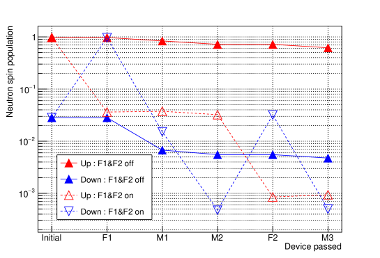
Using ideal, but experimentally feasible parameters, we set , , , , and . Using Eq. (5), we can calculate the neutron intensity after each component of the SFC, as shown in Fig. 1. For simplicity, it is assumed that .
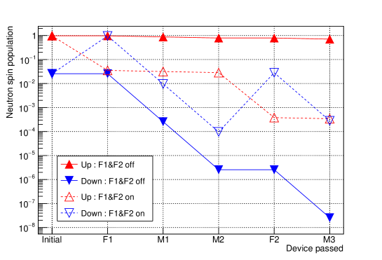
Here, the neutron vector after M1 reflection with the flipper-operated, , is expressed as
| (7) |
where the and components have the same order of magnitude. In this state, the effect of the spin flip is small, and the spin should be selected again. Therefore, M2 is required after M1. The neutron vector after M3 with flipper operation is expressed as
| (8) |
As is 0.71, can be achieved.
III Design of SFC
This Section describes the overall setup in subsection III.1 and then describes the individual devices in subsections III.2 and III.4. The calculation of the spin-flip efficiencies of these devices is presented in subsection III.5.
III.1 Overall Configuration
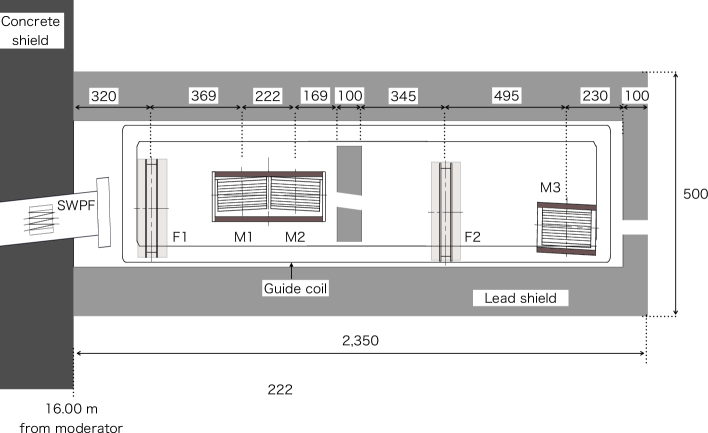
The SFC for the neutron lifetime experiment was installed on the polarized branch of BL05. The neutron flux at the exit of the beam branch is \qty4.0(0.3)e7\per\per\squared at a 1 MW equivalent [6], and the neutron polarization is [12]. In this study, the coordinates were defined in the beam direction as , vertically upward as , and as a right-handed system with respect to them. The SFC comprised three sets of magnetic supermirrors and two spin flippers, as shown in Fig. 2. These elements were installed in a 1 mT magnetic field applied by a Helmholtz-type guide coil to maintain neutron polarization. Polarized neutrons have spins parallel or anti-parallel to the -axis along the guide field.
The SFC was covered with 100-mm-thick lead to shield -rays resulting from neutron capture. The centers of F1 and F2 were located 320 and 1525 mm from the concrete surface (16.00 m from the neutron moderator), and M1, M2, and M3 were positioned at 689, 911, and 2020 mm, respectively. An additional 100 mm thick lead was installed between M2 and F1. This lead had a beam port of 39.5 mm 29.5 mm in vertical and horizontal direction. The lead downstream of M3 also contained a hole measuring 34.5 mm 29.5 mm. At the entrance and exit of the mirror sets, 5-mm-thick LiF tiles made by sintering a mixture of 95%-enriched 6LiF and PTFE at 30:70 wt% [13] were installed. The neutron beam was collimated to 30 mm 35 mm before and after M1M2 and 30 mm 40 mm before and after M3. The inner walls of the lead shield were covered with rubber containing B4C to absorb the scattered neutrons. The design for neutron transport and -ray shielding was completed using PHITS 3.20 [14].
III.2 Short Wavelength Pass Filter
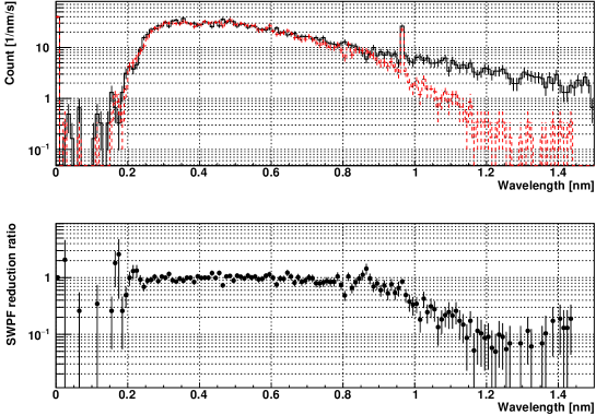
The pulsed neutron source at J-PARC operates with a repetition rate of 25 Hz. An event wherein neutrons produced by a pulse arrive later than neutrons from the next pulse is referred to as a frame overlap. Because the SFC is designed to flip only neutrons of specific wavelengths within a specific time-of-flight (TOF) interval, it cannot handle neutrons of different wavelengths arriving owing to the frame overlap. To remove the slower neutrons arriving as the flame overlapped, a short-wavelength pass filter (SWPF) was installed 20 cm upstream from the exit of the polarized beam branch. The SWPF comprised six supermirrors arranged shape with an angle of \qty3 relative to the beam, as shown in Fig. 3. The supermirrors were fabricated on a Si substrate with height, length, and thickness of 110, 125, and 0.3 mm, respectively, using a sputtering apparatus at the Research Reactor Institute, Kyoto University, with an -value (ratio of the critical reflection momentum transfer of the Ni mirror) of 3 [15].
The SWPF performance was evaluated by measuring the counts with and without the filter using a beam monitor (BM) at the exit of the polarized branch (16.4 m). The BM employed was CANBERRA MNH10/4.2F [16]. The detection efficiency followed the so-called law and was from the measurement compared to a 3He proportional counter, where is neutron wavelength. The measured spectra and their ratios are presented in Fig. 4. Wavelengths longer than 1.2 nm were successfully reduced by one order of magnitude.

III.3 Magnetic Mirror Assembly
In this upgrade, we used magnetic mirrors manufactured by Swiss Neutronics [17]. These mirrors were created by sputtering an Fe/Si multilayer film onto a Si wafer with 200, 100, and 0.3 mm in length, height, and thickness, respectively. Detailed specifications are listed in Table 1.
| Material | Fe/Si |
|---|---|
| Mirror size [mm] | |
| -value | 5.1 |
| Reflectivity at edge | 78% |
| Polarization | 98% |
The supermirrors were used as stacks comprising 8–10 mirrors assembled in the solar-slit style. For M1 and M2, the mirror configuration comprised eight plates each, while M3 was made of ten plates. The plates were fixed using an aluminum alloy fixture, which were designed to be parallel to the mirrors with a 5.9 mm interval.
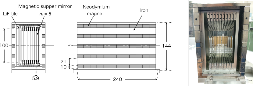
To obtain practical reflectivity, magnetic supermirrors must be sufficiently magnetized, which requires a magnetic field of at least 45 mT. Thus, the mirrors were operated in magnetic containers. In this SFC, the adjacent M1 and M2 were housed within the same magnetic container, whereas M3 was stored separately. The magnetic container had a structure comprising five neodymium magnets with iron sandwiched between them and capped at the top and bottom (Fig. 5). The magnetic field measured within the container was 58 mT near the center and 48 mT at the edges for the M1M2 container, and 52 mT at the center and 46 mT at the edges for the M3 container, thereby satisfying the required specification of over 45 mT throughout.
M1, M2, and M3 were located at \qty-1.6, +\qty1.6, and \qty-1.6 relative to the polarization beam branch, respectively. As the polarized branch was tilted \qty3.2 from the beamline axis, the neutrons exiting the SFC were designed to be transported in the same direction as the center axis of BL05 beamline.
III.4 Spin Flipper
There are two types of neutron spin flippers: adiabatic and resonant. Although the adiabatic type can achieve a high flipping efficiency, it is not suitable for the fast switching. Therefore, we employed a resonant-type spin flipper for the SFC. In the neutron lifetime experiment, -rays caused by the scattering and absorption of neutrons by wires in the beam axis are a major concern. Therefore, we continued to adopt -directed air coils as in the previous design. In the previous design, a guide coil was used to provide a magnetic field to define the quantization axis of the neutrons ( field) [8]. In the case of the new SFC, owing to the enlargement of the magnetic containers and the increase in the magnetic field strength, the magnetic field leakage to the coil can no longer be ignored. Thus, they were designed to apply a uniform -field (1 mT) by surrounding the flipper coil with an iron magnetic shield and installing ferrite magnets inside a magnetic container. Figures 6(A) and (B) show sketches of the flipper and downstream views, respectively. This design is less affected by external magnetic fields, and is compatible with another neutron lifetime experiment using magnetic field [18].
Ferrite magnets with residual flux density 300–400 mT, a thickness of 2 mm, and a width of 6 mm were mounted in three rows along the -axis to generate magnetomotive force. To ensure uniformity, iron poles with thickness and width of 1 and 6 mm, respectively, were mounted. The magnetic field distribution calculated using a three-dimensional magnetic field simulator is shown in Fig. 6(C). The magnetic fields measured at the centers of F1 and F2 with a Gauss meter were 1.18 and 1.08 mT, respectively, for a design value of 1.00 mT. The uniformity of the magnetic field was within 7% for F1 and 3% for F2 in the region from the coil center to mm, mm, and mm. A 1-mm-thick copper plate was installed around the RF coil, serving as an RF shield and confining the magnetic flux.
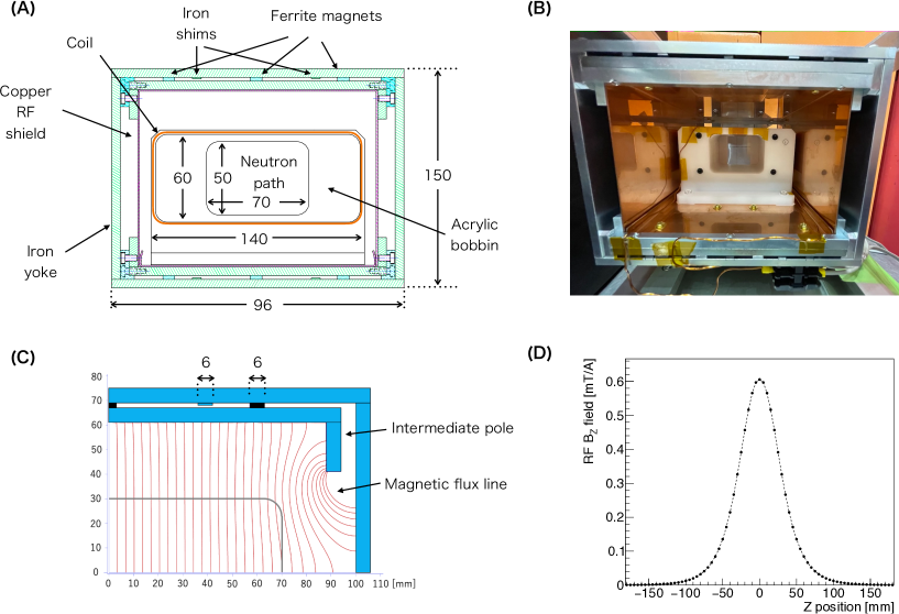
In the previous SFC, coils with diameter and length of 50 mm each were used. To expand the beam size, we enlarged the coil to 60 mm in length and 140 mm in width to apply a uniform RF magnetic field. The fringing field of the RF magnetic field generated by the coil along the -axis direction was parallel to , and perpendicular to along the -axis direction. The fringing field perpendicular to was a significant obstacle to spin-flip efficiency. Therefore, the size in the -direction was increased to avoid this magnetic field disturbance. The calculation of fringing field disturbance is discussed in the next subsection.
The details of the coils are listed in Table 2. Figure 6(D) shows the calculated RF magnetic-field strength of -direction at the center of the coil. The RF field intensity in the beam axis was roughly followed a Gaussian distribution, with a standard deviation of 30 mm.
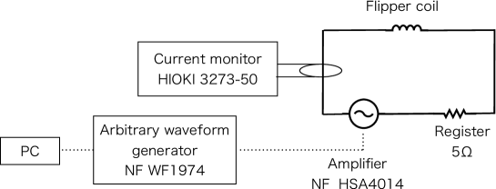
To operate SFC for pulsed neutrons, the RF current must be controlled according to the TOF. The circuit used to apply a time-dependent RF current is shown in Fig. 7. A waveform was generated using an arbitrary waveform generator, magnified using an amplifier, and applied to the coil. Here, only the resistance of the copper coil wire resulted in a time constant of , which does not satisfy the required flipping time (\qty100\micro) for the SFC. Therefore, a 5.0- resistor was inserted in series in the circuit to shorten the time constant to \qty20\micro. The frequency corresponding to the applied magnetic field was approximately 30 kHz, and the composite impedance at this frequency was 19.5 . As the maximum voltage of the amplifier was 50 V, a maximum current of 2.5 A could be applied.
By optimizing the neutron flip efficiency in any region of TOF, the RF current amplitude must be inversely proportional to the neutron velocity. In addition, the RF current was turned off based on the TOF when creating the bunch. These current controls were realized by inputting an ideal waveform created in 1-\unit\micro increments into an arbitrary waveform generator. The equation for flipping probability is explained in Section III.5. The actual bunching operation is explained in Section IV.3.
| F1 | F2 | |
|---|---|---|
| Coil size [mm] | ||
| Diameter of Cu wire [mm] | 1.2 | |
| Number of turns | 32 | |
| Inductance in shield (at 1 kHz) [\unit\microH] | 98.5 | 103.3 |
| Quality Factor | 2.91 | 2.72 |
| Coil resistance [] | 0.288 | 0.315 |
| Additional resistance [] | 5.0 | 5.0 |
| Phase [degree] | 75.1 | 74.5 |
| field [mT] | 1.18 | 1.08 |
III.5 Spin Flip Calculation
The spin flipper changes the direction of the neutron spin by inducing Larmor precession in static and RF magnetic fields. The orientation of the neutron spin in the magnetic field can be described by the following differential equation with respect to time :
| (9) |
where is the neutron gyromagnetic ratio of \qty1.832e8\per\per [19] and is the magnetic field vector experienced by the neutrons.
When the neutron is oriented to the field of magnitude , and an RF magnetic field of angular velocity and amplitude perpendicular to it is applied, the spin-flip efficiency is expressed as the following equation using the RF applied time, [20, 21]:
| (10) |
| (11) |
For , we have
| (12) |
Consequently, Eq. (10) can be simplified as
| (13) |
Thus,
| (14) |
This equation yields . Here, is an integer corresponding to the number of times the neutron spin rotates. In this SFC operation, we set , implying that it was rotated by within the coil.
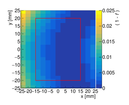
In reality, these equations are approximations owing to the nonuniformity of the magnetic field or fringing field from the coil. Therefore, we calculated the spin-flipping efficiency by implementing and RF field distributions obtained from simulation calculations using Eq. (9). In this calculation, the spin was treated as classical. The distribution of the spin-flip efficiency, which differs from unity , is shown in Fig. 8. In the calculations, the neutron velocity was assumed to be 1,000 m/s, field was 1 mT, and RF frequency was 29.2 kHz. Consequently, the current of the RF coil was optimized to achieve the maximum flipping efficiency. The results show that for the area within 30 mm 40 mm region (red line in Fig. 8) through which neutron can pass, the averaged efficiency was 99.8% and the worst was 99.0%.
IV Measurement
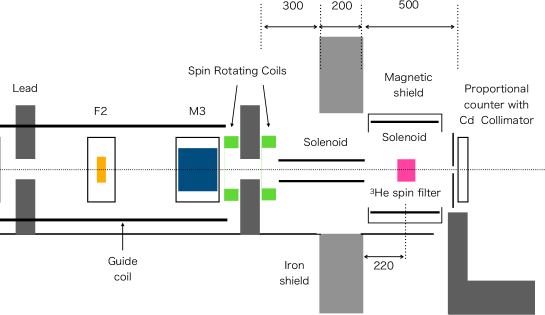
In this Section, the performance of the new SFC is evaluated. The beam fluxes at different positions along the beam path were measured using beam monitor detectors. The position and divergence distribution at the TPC were measured using a two-dimensional detector while scanning the position of the collimator installed at the exit of the SFC lead shield. The flipping efficiencies were optimized by considering the off-to-on ratio of the RF currents. Finally, beam polarization was measured using a 3He spin filter. The measurement configuration is shown in Fig. 9. The vacuum chamber for TPC and shielding was removed from these measurements. The results are discussed below.

IV.1 Neutron Flux
The neutron flux was measured at four positions: upstream of M1 (Pos.1), downstream of M2 (Pos.2), upstream of M3 (Pos.3), and upstream of the TPC shielding (Pos.4). These results are compared with the beam simulation by PHITS. The same BM used in Section III.2 was used at Pos.2–4, whereas a different BM with a lower detection efficiency of was used at Pos.1 to accommodate a higher count rate. To exclude the spread beam, an LiF-tile collimator with a hole of in and was mounted in front of the BM, and the fluxes were deduced by normalizing the total intensity to this area. The BM counts were converted to neutron flux using under the assumption of the law. Table 3 summarizes the neutron fluxes corresponding to the proton beam power of 1 MW. Note that the neutron with wavelengths of 0.32–0.78 nm were extracted (which can be reflected by the supermirrors) for comparison between the simulation and measurements.
| BM Position | Distance from Moderator [m] | Measured Flux [n/cm2/s] | Calculated Flux [n/cm2/s] | Ratio |
|---|---|---|---|---|
| Pos.1: Upstream M1 | 16.4 | 1 | ||
| Pos.2: Downstream M2 | 17.3 | 0.74 | ||
| Pos.3: Upstream M3 | 17.6 | 0.71 | ||
| Pos.4: Upstream TPC | 19.3 | 0.75 |
The PHITS calculation used the phase-space distribution at the exit of the polarized beam branch, whose absolute value was normalized by the flux at Pos.1. The flux ratio decreased by 26% from upstream M1 to downstream M2 but did not change thereafter. The decreases in M1 and M2 can be attributed to the divergence used in the calculation being smaller than the actual values. The TOF spectra of the BM before and after the upgrade at Pos.4 are shown in Fig. 10. The BM counts increased by a factor of 3.2 times the previous. Because the number of neutron decays per unit length is inversely proportional to the neutron velocity, the increased factor directly corresponds to neutron decay. Consequently, the rise timing in TOF shifted 20% backward compared to the previous time owing to the alignment changes.

IV.2 Flipping Efficiency
Under condition of Pos.4 in Section IV.1, we optimized the RF frequencies and currents of F1 and F2 to obtain a higher flipping efficiency. When the frequency satisfied Eq. (12), became Eq. (13), and the flipping efficiency exhibited a simple sine function on the TOF when the RF current was fixed. Thus, we obtained the spectra of on the TOF by considering the ratio of with the RF on to off and fitting them with the function
| (15) |
where denotes the flipper perfection. In this context, represents TOF of the pulsed neutrons, whereas denotes the moment when reaches its minimum, at which point equals . Initially, we tuned the RF frequency to maximize .
Figure 11 shows the spectra of , where the RF current was adjusted to its minimum value at 30 ms (equivalent to a wavelength of 0.61 nm) after frequency optimization. From the top, the spectra for F1, F2, and F1 and F2 operating simultaneously are shown. The frequencies that yielded the maximum were 32.2 kHz for F1 and 30.6 kHz for F2. The spectra were fitted using Eq. (15) for F1 and F2, and square of Eq. (15) for the simultaneous operation of F1 and F2. The maximum flipping efficiencies corresponding to in the fit were 96.6% for both F1 and F2, and 95.5% for the simultaneous operation. The minimum values for F1 and F2 were 3.96 0.18% and 3.85 0.18%, respectively, which are 16% larger than . The simultaneous operation worsened to 0.330 0.020%, which is 63% larger than the value indicated by and 2.2 times larger than the product of single operations. Depolarization of the polarizing mirror was suspected to be the cause. A quantitative discussion is provided in Section IV.5.

IV.3 Neutron bunching operation
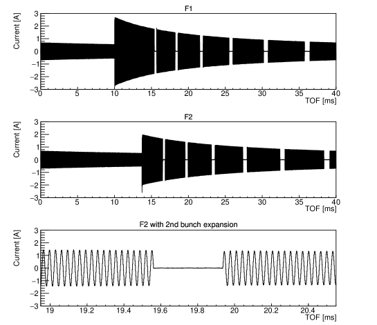
When dumping neutrons in all TOF regions, the RF current is inversely proportional to the neutron velocity; that is, , where is the initial current at the time of pulse-frame switching. The frame switching occurred at 10 ms in F1 and was accordingly adjusted to 13.7 ms in F2. When creating a bunch, the RF currents were cut. The operation mode wherein all beams enter the TPC by cutting the RF is called the passing mode. Conversely, the dumping mode refers to the condition wherein all neutrons are absent during the application of RF currents. The bunching condition used in the neutron lifetime experiment was termed the bunching mode. The RF currents monitored during the bunching mode are shown in Fig. 12. The RF currents were controlled by the voltage applied to the amplifier. The phases of the voltage and current were shifted by \qty75, as indicated by the inductances of the coils listed in Table 2. Considering this, voltage switching was performed when the current was zero.
The detection length along -axis must be sufficiently small to measure the rise time of a bunch. Thus, instead of the BM, a two-dimensional detector (RPMT [22]) using a 0.4-mm-thick ZnS scintillator for neutron detection was employed. The detection efficiency of RPMT was . The RPMT was installed at a position corresponding to the center of the TPC. Because the RPMT could not receive all beams in terms of counting, a pinhole was installed at the SFC lead exit, and a scan was performed in 1 mm steps. This measurement enabled the three-dimensional reconstruction of the position and divergence distribution of the neutron beam from the SFC and its use in simulations of the neutron lifetime experiment.
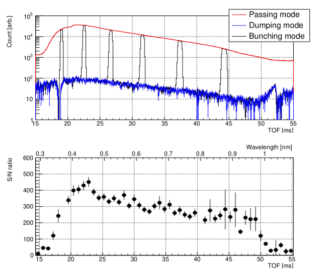
Figure 13 shows the TOF distribution obtained using the RPMT in passing, dumping, and bunching modes. For convenience, the TOF of 0–15 ms is displayed as 40–55 ms. In bunching mode, because neutrons hitting the magnetic mirror or beam dump cause -rays to become the background source, the SFC bunch interval was adjusted to ensure that other bunches were not present at positions generating backgrounds while a certain neutron bunch was in the TPC. The neutron bunch width was adjusted to 40 cm, and the distance between the end of one bunch and the tip of the next bunch was set to 3.4 m. In the present upgrade, the number of bunches in a pulse was increased from the previous five to six because longer-wavelength neutrons can now be used. The rise time of the bunch was obtained by fitting with an error function, and its 1 was \qty63\microsec for the first peak and \qty97\microsec for the sixth peak. These rise times correspond approximately to the time when neutrons pass through 60 mm, which corresponds to 2 of the RF field width, as shown in Fig. 6(D). The S/N of SFC (passing mode divided by dumping mode) is shown at the bottom of Fig. 13. The S/N values were in the range of 250–400 for all the bunch regions.
IV.4 Polarization Measurement
Based on the discussion presented in Section II, neutron polarization after passing through the SFC can be used to evaluate the performance of the magnetic mirror and flipper. Therefore, we measured the polarization at the front of the TPC by using a 3He spin filter. The experimental setup is shown in Fig. 14.
The 3He spin filter is a device that controls neutron polarization, utilizing the property that the neutron capture cross-section varies greatly depending on the neutron polarization direction. In this study, we used an 3He filled glass vessel with diameter and length of 40, and 90 mm, respectively, filled at a pressure of Pa (HANABISHI, ) [23]. The spin filter was placed at the center of a solenoid magnet covered with a magnetic shield and a magnetic field of 1.5 mT was applied. Neutrons were polarized along the -direction (vertical direction) using a guide coil. Two spin rotation coils with diameter of 100 mm were installed before and after the lead at the SFC exit to adiabatically rotate the polarization direction of the neutron beam from the -axis to the -axis. When the magnetic field of the spin rotation coils was applied at 3.6 mT, the depolarization for neutrons with a velocity of 1000 m/s (wavelength 0.4 nm) was calculated to be , which is sufficient for the measurement accuracy in this study. The neutron beam passing through 3He was detected using a 3He proportional counter collimated to a 10-mm square.
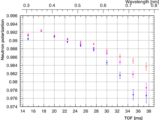
Helium-3 was polarized using the spin-exchange optical pumping (SEOP) method. The polarization of neutrons and 3He can be deduced by measuring the transmission through the polarized, spin inverted via an adiabatic fast passage, and completely unpolarized 3He. This method is described in detail by ref. [23]. The initial 3He polarization was approximately 70% and decreased over time. The results of the neutron polarization measurements are shown in Fig. 15. The measurements were performed while changing the magnetic field of the spin-rotation coils to 3.6, 7.2, and 10.8 mT. A polarization was 99.2 % for the neutrons arriving at 18 ms. From there, the polarization tends to decrease with slower neutrons, and a magnetic field dependence of the rotating coil was observed for polarization with wavelengths longer than 0.5 nm. Because the effect of non-adiabatic depolarization should be less than and expected smaller for longer wavelengths or higher magnetic field, it is unlikely that depolarization along the pass caused the drop. The magnetic field caused by the spin-rotation coils may have affected the reflectivities of the magnetic mirrors; however, the cause was not identified.
IV.5 Discussion on SFC Performance
In this subsection, we discuss the performance of the developed SFC. The S/N measured by RPMT, as shown in Fig. 13 was 250–400, while the ideal S/N of the SFC was estimated to be 1000 in Section II. The lower S/N could be attributed to the depolarization at the magnetic mirror, as inferred from the measurements of the spin flippers in Section IV.2 and the polarization in Section IV.4. In particular, the polarization measured by the 3He spin filter was approximately , which is significantly worse than its ideal value and the value calculated under adiabatic conditions of in Fig. 1. Even if the initial neutron beam has no spin component, the polarization is degraded when a spin-flip reflection occurs in the magnetic mirror. In the calculations in Section II, and were treated as zero. If is , then the polarization after M3 was obtained as .
Thus, we recalculated the flipping efficiencies and mirror reflectivities including the spin-flip reflection, to explain the experimental values. Four parameters were set as free parameters: and for the flipping efficiencies of F1 and F2, for the reflectivity of the magnetic mirror for spin , and for reflectivity with a spin flip. The optimal values of these parameters were derived by global fitting of the four experimental values: the lowest values for F1 and F2, and the simultaneous operation of F1 and F2 as shown in Fig. 11, and the polarization % was measured with the 3He spin filter at 30 ms, for magnetic field of the spin rotation coil of 3.6 mT. The flipper measurements were performed without spin rotation coils; thus, we used polarization with a minimum coil field of 3.6 mT. The results are presented in Table 4, and the corresponding spin states are shown in Fig. 16.
| 99.30 0.17 % | |
| 98.85 0.22 % | |
| 1.42 0.11 % | |
| 0.65 0.02 % | |
| S/N | 429 |
The spin-flip efficiencies of and were approximately 99%, which is comparable to the flipping efficiency calculated in Section III.5. The value of was close to 1%, which is the specification value in Table 1. was calculated to be 0.65 0.02%, matching the value for Fe/Si () at a 50 mT magnetic field as per reference [24]. The calculated S/N of 429 was also closer to the experimental value of 303 than to the ideal calculated value. According to ref. [25], a magnetic field of over 200 mT is required to reduce depolarization to below 0.1%. It is considered that the magnetic field of the current magnetic mirror holder is not sufficiently large to minimize . If is achieved with an adequate magnetic field, an S/N of 730 and a polarization of 99.8% can be realized.
V Signals in TPC
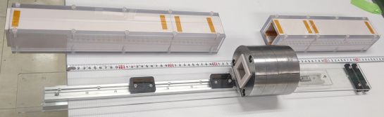
In this Section, we discuss the neutron signals in the TPC. In the neutron lifetime experiment, the neutrons were shaped into bunch lengths of 40 cm at SFC and transported to TPC, which was housed in a vacuum vessel covered with lead shielding and a cosmic-ray veto counter. The upgrade of the SFC resulted in a 3.2-fold increase in the beam quantity upstream of the TPC in terms of decay events. However, this also increased the neutron beam width and divergence, as well as the amount of -rays, owing to neutron capture by the magnetic mirror. To mitigate these increases, a new lead collimator, 100 mm in length and 36 mm in inner diameter, was installed between the guides upstream of the TPC made of LiF tiles. The lead collimator was located 300 to 400 mm upstream from the TPC. LiF tiles with a 30 mm square hole were installed upstream and downstream of the lead collimator to define the size of the neutron beam entering the TPC. The inner surface of the lead collimator was also covered with LiF to absorb the scattered neutrons. The photo of the collimator and LiF guides are shown in Figure 17.
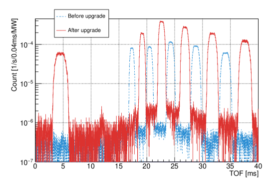
The impact of the SFC upgrade was clearly demonstrated in the TOF spectra of the 3He(n,p)3H reaction with the TPC both before and after the upgrade, as shown in Fig. 18. The gas mixture was set to 83 kPa for He and 15 kPa for CO2, which are the standard measurement settings for lifetime measurements [4]. In addition, 3He was introduced into the gas mixture, resulting in a number density of . The upgrade resulted in a 3.2-fold increase in the 3He(n,p)3H reactions as well, while maintaining comparable S/N and time widths, as before the upgrade reported [26]. A small peak appeared at approximately 12 ms, corresponding to 1/1000 of the neutron bunches, owing to the frame overlap. This region was used in the lifetime analysis as a background region; however, it did not affect the neutron lifetime because the neutrons entering this background region were considered.
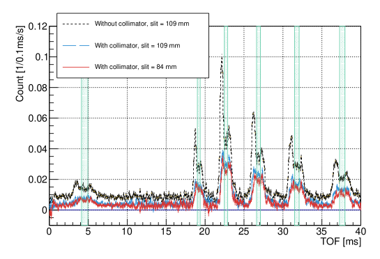
The TOF spectra for selecting the decay candidate events using the new SFC are shown in Fig. 19. As in the neutron lifetime experiment [4], the decay candidate signals were derived by subtracting the shutter closed signal from the shutter open signal. Owing to the enlarged aperture of the SFC, peaks occurred in TOF corresponding to before and after the neutron bunch. This is considered to be caused by the neutrons hitting the LiF guides owing to the increased divergence. Installing a lead collimator mitigated these peaks. Additionally, events in the 10–15 ms range, where no neutrons were present, also decreased. These events are likely residual radiation from 20F and 8Li absorbed by the LiF guide because the shutters opened and closed every 1000 s and the causal radioactivities must decay faster than that time [4].
Because the divergence of the neutron beam is larger in the vertical direction than in the horizontal direction, reducing the vertical width from 109 to 84 mm using a slit located 12 m from the neutron target in the polarized branch further decreased the peaks before and after the bunches. By setting the vertical slit to 84 mm, the count of 3He(n,p)3H events decreased by 10.1% compared with the 109 mm condition. Consequently, under these settings, the neutron count increased by 2.8 times compared to that of the original SFC.
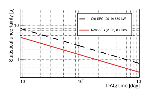
The statistical accuracy under the optimal conditions (red in Fig. 19), estimated from the number of decay candidate signals and backgrounds, are shown in Fig. 20. The calculated beam power was 830 kW. The measurement time to reach a statistical accuracy of 1 s was improved from 590 days to to 170 days by the SFC upgrade. These measurement times were calculated and did not include detector calibrations, which accounted for approximately 10% of the total.
VI Summary
In the neutron lifetime experiment using the pulsed neutron beam at J-PARC, the statistics was limited by the acceptable beam size at the SFC. In this study, the sizes of the magnetic mirrors and spin flippers were enlarged to improve the neutron intensity. The magnetic container was made of neodymium and iron magnets, ensuring that the magnetic field was greater than 46 mT over the entire region. The neutron flux before TPC measured by the BM was converted to 1 MW at cm-2/s, which is 75% of the value calculated by PHITS.
The structure of the spin flipper was redesigned to mitigate the effects of flinging fields from the magnetic container. A -magnetic field was generated inside the ferrite magnets in the iron shield box, and the RF coil was housed inside it. The timing of the neutron spin flip can be freely selected by amplifying the output of an arbitrary waveform generator to control the RF coil current. The rise time in the bunching mode was \qtyrange6397\micro at 1 of the error function, which is equivalent to twice the standard deviation of the magnetic field distribution by the RF coil.
The neutron reduction rate under optimized RF conditions was approximately 3.9% for both F1 and F2, and 0.33% for simultaneous operation. The result of the simultaneous operation was 2.2 times worse than that expected from square of the single flipper operation. The spin polarization of the neutrons after SFC was measured using a 3He spin filter and obtained as 97.6–99.2%. Further, wavelength dependence was observed, with slower neutrons exhibiting worse polarization. The polarization tended to increase as the magnetic field strength of the coil used for the spin rotation increased. From the measured values, the flipper efficiencies ( and ), reflectivity for spin (), and spin-flip reflectivity () were obtained via global fitting. and were 99% and 1.4%, respectively, for , which are reasonable values derived from the design. was calculated to be 0.65 0.02%. It is considered that the magnetic field on the mirrors was not sufficient to have a sufficiently small and could be improved by increasing the magnetic field of the mirror container.
The 3He(n,p)3H reaction count in the TPC, normalized by the proton beam power and 3He number density, was enhanced 2.8 times by the improvement in the SFC. Consequently, the time to reach a statistical accuracy of 1 s for the neutron lifetime experiment improved from 590 to 170 days with a proton beam power of 830 kW. This improvement in statistical accuracy will also contribute to the reduction of systematic uncertainties, such as background evaluation, fostering further advancements in the neutron lifetime experiments at J-PARC.
ACKNOWLEDGE
This work was supported by JSPS KAKENHI Grant Number (16H02194, 19H00690, and 22H00140). The neutron experiment at the Materials and Life Science Experimental Facility of J-PARC was performed under a user program (Proposal Nos. 2015A0254, 2019B0341, 2020A0223, 2021B0287 and 2022A0117) and an S-type project of KEK (Proposal Nos. 2014S03 and 2019S03). Magnetic mirrors and flippers were installed at the CN3 beam port of KUR with the approval of the Institute for Integrated Radiation and Nuclear Science, Kyoto University (Proposal Nos. 30086 and 31030).
References
- [1] Grant J Mathews, T Kajino, and T Shima, Physical Review D, 71(2), 021302 (2005).
- [2] R. L. Workman and Others, PTEP, 2022, 083C01 (2022).
- [3] G. Mention, M. Fechner, Th. Lasserre, Th. A. Mueller, D. Lhuillier, M. Cribier, and A. Letourneau, Phys. Rev. D, 83, 073006 (Apr 2011).
- [4] K Hirota, G Ichikawa, S Ieki, T Ino, Y Iwashita, M Kitaguchi, R Kitahara, J Koga, K Mishima, T Mogi, et al., Progress of Theoretical and Experimental Physics, 2020(12), 123C02 (2020).
- [5] K. Mishima, T. Ino, K. Sakai, T. Shinohara, K. Hirota, K. Ikeda, H. Sato, Y. Otake, H. Ohmori, S. Muto, et al., Nucl. Instrum. Methods Phys. Res. A, 600(1), 342–345 (2009).
- [6] K. Nakajima, Y. Kawakita, S. Itoh, J. Abe, K. Aizawa, H. Aoki, H. Endo, M. Fujita, K. Funakoshi, W. Gong, et al., Quantum Beam Science, 1(3), 9 (2017).
- [7] Y. Arimoto, N. Higashi, Y. Igarashi, Y. Iwashita, T. Ino, R. Katayama, M. Kitaguchi, R. Kitahara, H. Matsumura, K. Mishima, N. Nagakura, H. Oide, H. Otono, R. Sakakibara, T. Shima, H.M. Shimizu, T. Sugino, N. Sumi, H. Sumino, K. Taketani, G. Tanaka, M. Tanaka, K. Tauchi, a. Toyoda, T. Tomita, T. Yamada, S. Yamashita, H. Yokoyama, T. Yoshioka, et al., Nucl. Instrum. Methods Phys. Res. A, 799, 187–196 (2015).
- [8] K. Taketani, T. Ebisawa, M. Hino, K. Hirota, T. Ino, M. Kitaguchi, K. Mishima, S. Muto, H. Oide, T. Oku, et al., Nucl. Instrum. Methods Phys. Res. A, 634(1), S134–S137 (2011).
- [9] B. Märkisch, H. Mest, H. Saul, X. Wang, H. Abele, D. Dubbers, M. Klopf, A. Petoukhov, C. Roick, T. Soldner, and D. Werder, Phys. Rev. Lett., 122, 242501 (Jun 2019).
- [10] RI Bewley, JW Taylor, and SM Bennington, Nuclear Instruments and Methods in Physics Research Section A: Accelerators, Spectrometers, Detectors and Associated Equipment, 637(1), 128–134 (2011).
- [11] Physica B: Condensed Matter, 335(1), 263–265, Proceedings of the Fourth International Workshop on Polarised Neutrons for Condensed Matter Investigations (2003).
- [12] T. Ino, Y. Arimoto, T. Yoshioka, K. Mishima, K. Taketani, S. Muto, H. M. Shimizu, H. Kira, Y. Sakaguchi, T. Oku, et al., Physica B, 406(12), 2424–2428 (2011).
- [13] J. Koga, S. Ieki, A. Kimura, M. Kitaguchi, R. Kitahara, K. Mishima, N. Nagakura, T. Okudaira, H. Otono, H.M. Shimizu, N. Sumi, S. Takada, T. Tomita, T. Yamada, and T. Yoshioka, Journal of Instrumentation, 16(02), P02001 (feb 2021).
- [14] Tatsuhiko Sato, Yosuke Iwamoto, Shintaro Hashimoto, Tatsuhiko Ogawa, Takuya Furuta, Shin-Ichiro Abe, Takeshi Kai, Yusuke Matsuya, Norihiro Matsuda, Yuho Hirata, et al., Journal of Nuclear Science and Technology, pages 1–9 (2023).
- [15] M. Hino, H. Sunohara, Y. Yoshimura, R. Maruyama, S. Tasaki, H. Yoshino, and Y. Kawabata, Recent development of multilayer neutron mirror at kurri, volume 529, pages 54–58 (8 2004).
- [16] T Ino, H Otono, K Mishima, and T Yamada, 528(1), 012039 (2014).
- [17] C Schanzer, M Schneider, and P Böni, Neutron optics: Towards applications for hot neutrons, In Journal of Physics: Conference Series, volume 746, page 012024. IOP Publishing (2016).
- [18] Naoyuki Sumi, Go Ichikawa, Kenji Mishima, Yasuhiro Makida, Masaaki Kitaguchi, So Makise, Shun Matsuzaki, Tomoya Nagano, Masaki Tanida, Hideaki Uehara, Kodai Yano, Hidetoshi Otono, and Tamaki Yoshioka, Nuclear Instruments and Methods in Physics Research Section A: Accelerators, Spectrometers, Detectors and Associated Equipment, 1045, 167586 (2023).
- [19] Eite Tiesinga, Peter J Mohr, David B Newell, and Barry N Taylor, Journal of Physical and Chemical Reference Data, 50(3) (2021).
- [20] I. I. Rabi, Phys. Rev., 51, 652–654 (Apr 1937).
- [21] B Alefeld, Gerald Badurek, and Helmut Rauch, Zeitschrift für Physik B Condensed Matter, 41, 231–235 (1981).
- [22] Katsuya Hirota, Takenao Shinohara, Kazuaki Ikeda, Kenji Mishima, Tomohiro Adachi, Takahiro Morishima, Setsuo Satoh, Takayuki Oku, Satoru Yamada, Hajime Sasao, et al., Physical Chemistry Chemical Physics, 7(8), 1836–1838 (2005).
- [23] T Okudaira, T Oku, T Ino, H Hayashida, H Kira, K Sakai, K Hiroi, S Takahashi, K Aizawa, H Endo, et al., Nuclear Instruments and Methods in Physics Research Section A: Accelerators, Spectrometers, Detectors and Associated Equipment, 977, 164301 (2020).
- [24] Christine Klauser, Thierry Bigault, Peter Böni, Pierre Courtois, Anton Devishvili, Nataliya Rebrova, Michael Schneider, and Torsten Soldner, Nuclear Instruments and Methods in Physics Research, Section A: Accelerators, Spectrometers, Detectors and Associated Equipment, 840, 181–185 (12 2016).
- [25] AK Petoukhov, VV Nesvizhevsky, T Bigault, P Courtois, A Devishvili, D Jullien, and T Soldner, Review of Scientific Instruments, 94(2) (2023).
- [26] Go Ichikawa, Yasuhiro Fuwa, Takuro Hasegawa, Masahiro Hino, Katsuya Hirota, Takashi Ino, Yoshihisa Iwashita, Masaaki Kitaguchi, Jun Koga, Shun Matsuzaki, et al., Proceedings of Science, 380, 457 (2022).