Coherence time of 20 s with a single cesium atom in an optical dipole trap
Abstract
We analyze the decoherence between two ground electronic states of an optically trapped atom by adopting a full description of the atomic wavefunction. The motional state, i.e., the phonon state, is taken into account. In addition to the decoherence due to the variance of differential light shift (DLS), a new decoherence mechanism, phonon-jumping-induced decoherence (PJID), is discovered and verified experimentally. A coherence time of s is then obtained for a single Cs atom by suppressing both variances of DLS and PJID by trapping the atom in a blue-detuned BBT and preparing the atom into its three-dimensional motional ground states. Our work opens a new prospect to extend the coherence time of optically trapped single atoms.
The systems of optically trapped neutral single atoms are important platforms for quantum metrology [1, 2, 3, 4], quantum measurement [5, 6], quantum computation [7, 8], and quantum simulations [9, 10, 11]. Usually, ground-state Zeeman sublevels, such as clock states, are adopted for applications. The coherence time () between the Zeeman states is thus one of the key factors for the high performance in these applications, and a long time is always pursued. To date, over 30 s times has been achieved for optically trapped single strontium atoms [2, 12]. The coherence time is obtained by either using optical tweezer traps with a “magic wavelength” [2], where the differential light shift (DLS) between the two clock states can be cancelled, or nuclear spins [12]. Thus, coherence is intrinsically immune to fluctuations in the trapping light intensity.
However, for widely used alkali metal atoms, such as rubidium atoms and cesium atoms, the time between the microwave clock states of optically trapped single atoms is much shorter due to the lack of a “magic wavelength”. The DLS between two clock states is susceptible to fluctuations in the trapping light intensity [13]. In recent years, many efforts have been made to improve the time of optically trapped alkali metal atoms by finding other “magic conditions” [14, 15, 16, 17, 18, 19, 20, 21, 22, 23, 24], where the first-order dependence of the DLS on fluctuations in light intensity and/or magnetic fields could be suppressed. By applying such “magic conditions”, the time can be improved from tens of milliseconds to the second level. However, without using “magic conditions”, the longest time of 12.6 s for single cesium (Cs) atoms in blue-detuned traps was reported recently [25]. The underlying mechanism is still unclear.
In this Letter, we discover a new mechanism of decoherence, which is caused by the stochastic jumping of the atomic phonon state due to trapping noise. We therefore name this decoherence mechanism as the phonon-jumping-induced decoherence (PJID). The mechanism results in an exponential decay of the coherence, which differs from the Gaussian decay of the decoherence caused by the variance of the DLS. The two mechanisms take place simultaneously in the decoherence process. By examining the decoherence process of a Cs atom in a red-detuned optical trap with different intensity noise levels, we solidly prove the existence of PJID. By suppressing the PJID elaborately in a blue-detuned bottle beam trap (BBT), we obtain a coherent time of about 20 seconds between the clock states of a single trapped Cs atom. To the best of our knowledge, this is the longest coherence time for a single optically trapped alkali metal atom, and it can be improved further by improving the phase noise of the driving microwave, the pointing noise of the trap, etc.
To understand the PJID, besides the two internal electronic states and , we have to take the external vibrational quantum states (phonon states) of the atom in a trap into account of the full quantum wavefunction. The motion of the trapped atom is described by a three-dimensional (3D) quantum harmonic oscillator. The atom vibrational states (phonon states) are denoted by , where is the phonon number (PN) along vibrational axis (, , or ). The phonon states obey the orthogonal relation . In a rotating frame associated with the atom frequency between states and , the time-dependent full wavefunctions of the atom can be expressed as and . Here, is the DLS between states and [26], and is the additional phase. is the ratio between the hyperfine splitting and the frequency detuning of the trap light. is the potential at the trap center, and is the oscillation frequency. The coherence between the two states is
| (1) |
where and are the probability distributions of and , respectively. The trace is made over both the electronic and phonon state spaces. Then, it can be rewritten as
| (2) |
We first discuss the DLS-dependent part of Eq. (2), which can be separated as
| (3) |
For a given spatial structure of the optical trap, the potential and trap frequency are determined by the total trap power . The probability distribution of usually follows a Gaussian function with and as the mean and root mean square (rms) values of the total trap power. The probability distribution of also follows a Gaussian function with , where is the mean value of DLS. The variation of the DLS () depends on by
| (4) |
By setting , the decay of the coherence given in Eq. (3) will finally take a Gaussian form
| (5) |
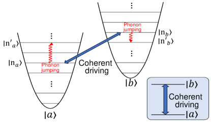
Next, we will discuss the rest of Eq. (2), which is connected to the stochastic jump between the phonon states induced by the noise of the trap light. As a consequence, the jump of either the PN or the phase would cause decoherence. As shown in Fig. 1, the two sets of phonon states in the trap potentials formed by the light shift of the two electronic states and are independent. Due to the randomness of the trap light noise, the noise-induced quantum jumps of the PN in the two traps occur stochastically and independently. We assume that the atom is initially prepared in a superimposed state of and with by a coherent driving field. Supposing that the PN associated with one electronic state is alternated due to the noise at time , according to Eq. (2), the coherence collapses immediately because of due to . Here, and are the PNs at time . Even the PNs are alternated simultaneously to the same number () at time , and the coherence also disappears due to the stochasticity of the noise-induced phonon jumping process. In this case, the phase in Eq. (2) is evenly distributed in the range [0, 2) with . Therefore, and the coherence .
The process of decoherence is determined by the jumping rate of the PN. If we define the jumping rate from PN along axis as , the probability of the atom being in state is . Then, obeys the rate equation . Hence, the coherence takes the form
| (6) |
In an optical trap, phonon jumping is induced by the intensity noise and the beam-pointing noise associated with the trap light [27, 28]. The intensity (beam-pointing) noise will cause the PN to jump by two (one). The overall phonon jumping rate (PJR) from state is the sum of all the jumping rates given in [27, 28], and the result is
| (7) |
where is the mass of the trapped atom and is the trap frequency along axis . and are the one-sided power spectra of the fractional fluctuations in spring constant and coordinate .
Finally, we obtain the decay of the overall coherence
| (8) |
where is the overall phonon jumping rate (PJR). We see that the coherence actually shows a Gaussian and exponential combined decay.
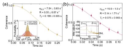
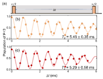
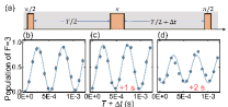
To experimentally prove the existence of PJID, we measured two coherence decays in a red-detuned ODT with different intensity noise levels. The ODT is formed by strongly focusing a 1052-nm laser beam to a size of 1.65 m and loads single Cs atoms from a magneto-optical trap (MOT). The coherence between the clock states ( and ) was measured by standard spin-echo interferometer [29, 30] with a 9.2-GHz microwave driving field. Figure 2(a) and (b) shows the coherence data for different time delays under the condition that the trap laser is free running and 40 dB intensity noise is added in a frequency range that covers the trap frequencies. In Fig. 2(a), the coherence decays more like a Gaussian function because of the low PJR. The data fitting by Eq. (8) gives a DLS variation s-1 and a PJR s-1. The corresponding ms, which is defined by of the coherence. However, the coherence data in Fig. 2(b), where the 40-dB intensity noise is added to the trap light, apparently deviates from the Gaussian function, and the coherence time is ms. In this situation, Eq. (8) gives good data fitting, and the fitted DLS variation and PJR are s-1 and s-1, respectively. Compared to the condition in which the laser is free running, the DLS variation is increased by a factor of two, which is in agreement with the enhancement () of the variance of the trap light intensity [inset of Fig. 2(a)]. The PJR is increased by 5.14 s-1, which comes from the parametric process-induced phonon jumping [the first term in Eq. (7)] because the second term remains the same in the two situations. By using the measured intensity noise [inset of Fig. 2(b)], the increase in the PJR can be estimated as 6.0 s-1 [31], which agrees well with the number obtained by the data fitting. Therefore, the existence of PJID can be confirmed solidly.
A long coherence time can be obtained by suppressing both the DLS variance and PJR. The DLS variance can be greatly suppressed by adopting red-detuned optical traps with “magic conditions” [14]. However, because the atom is confined in the region of intensity maxima, the decoherence induced by photon scattering is also maximized [31]. In a well-aligned blue-detuned trap, the atom is trapped in the region with zero light intensity in principle. Thus, the decoherence induced by photon scattering is completely canceled. The main term of DLS [the first term on the right-hand side of Eq. (4)] also disappears. The rest of the DLS due to the phonon energy can be suppressed by preparing the atom in its motional ground states (). In addition, a phonon-state-dependent “magic condition” for a blue-detuned trap can also be applied to suppress the total DLS variance [26].
As given by Eq. (7), the PJR is determined by the trap frequency , intensity noise , pointing noise , and PN . Therefore, it can be suppressed by reducing these parameters. The trap frequency is determined by the depth and size of the optical trap and thus can be reduced by using a trap with shallow depth and large size. The intensity noise can be suppressed by applying a noise eater or adopting a low-noise laser. The pointing noise can be minimized by improving the mechanical stability of the trap optics. The most efficient way to suppress the PJR is to decrease the PN, which can be achieved by preparing the atoms into the vibrational ground states. If the atom can be prepared in its three-dimensional (3D) motional ground state (zero phonon state, ZPS), i.e., , the PJID can be minimized.
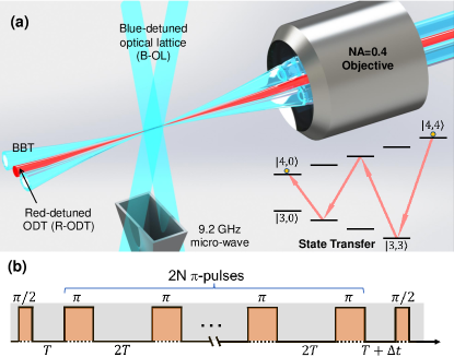
Here, we adopt a blue-detuned optical bottle beam trap (BBT) to demonstrate the long coherence of a single Cs atom by suppressing both the DLS variance and the PJR. The trap is formed by focusing two parallelly propagating 780-nm vortex laser beams with orthogonal polarization by a single objective with numerical aperture [Fig. 3(a)]. Therefore, the two beams cross each other around the focus of the objective, and a microsized BBT is formed [32]. The radius and length of the BBT are m and m. The details of the trap construction can be found in the Supplementary Materials [31]. The intensity ratio between the trap center and the trap barrier is 1.5%. Thus, the DLS variance can be greatly reduced by using a shallow trap depth and preparing the atom in its motional 3D ground states. The PJR can also be suppressed by adopting a low intensity noise laser and improving the mechanical stability of the trap. We use a 780-nm external-cavity diode laser to build the trap. The output has a very low intensity noise [inset of Fig. 4(a)], and the relative intensity variance is smaller than 0.015%. By using a trap power of 9 mW, we can build a trap with a minimum barrier of K ( is the Boltzmann constant). The trap frequencies are kHz. For a Cs atom in its 3D ZPS, the estimated DLS variance and the PJR due to the intensity noise are s and s. The pointing noise of the BBT is hard to measure, and it is improved by mounting all the optics with the cage system from Thorlabs. With the atom in its 3D ZPS, the PJR due to the pointing noise can also be minimized. Therefore, a long time is expected.
The single atom in its 3D ZPS is prepared with the aid of a combined microsized ODT. The experimental sketch is displayed in Fig. 3(a) and the experimental details can be found in SM [31]. Resolved Raman sideband cooling (RSC) is used to prepare the atom in its 3D ZPS, and the residual phonon numbers are [33]. The atom is transferred to by four microwave -pulse via the intermediate states , , and . Spin-echo between the Cs clock states ( and ) is performed to evaluate the decay of the coherence.
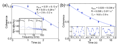
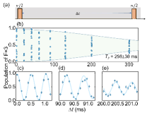
The coherence decay measured by spin-echo interferometer is displayed in Fig. 4(a). The data show a Gaussian function decay, and the fitting by Eq. (8) gives DLS variance s-1 and PJR s-1. The corresponding coherence time is s. The DLS variance is much larger than we estimated. The reason probably comes from the slow disturbance of the energy levels caused by the variations in the magnetic field around and the BBT light field which are not taken into account in the discussions above. A Carr-Purcell-Meiboom-Gill (CPMG) pulse sequence is then applied to decouple the spin dynamics from these slow disturbances [34, 35]. The pulse sequence is shown in Fig. 3(b), where a series of -pulses are inserted between the two -pulses. The time interval s is chosen for its best performance. The CPMG pulse sequence works as a filter that can filter out the slow DLS variations with frequencies Hz (). The obtained decay of coherence turns out to be much slower. The data are shown in Fig. 4(b). The residual DLS variance and PJR are fitted by Eq. (8) with s-1 and s-1. The small DLS variance might come from the residual variations of the magnetic field and BBT light. The stability and phase noise of the microwave source may also contribute to the DLS variance. The main source of the residual PJR should be induced by the pointing noise of the BBT. All of these factors could be suppressed further by using proper methods. In the current case, the coherence time is s. Accounting for the single atom lifetime of s [31], the actual coherence time should be s.
In summary, we analyzed the decoherence between two ground electronic states of an optically trapped atom by adopting a full description of the atomic wavefunction, in which the motional wavefunction is considered. A new decoherence mechanism, i.e., the phonon-jumping-induced decoherence, is discovered and verified experimentally. By adopting a blue-detuned BBT and preparing the atom into its 3D ZPS, both the DLS variance and the PJID can be dramatically suppressed, and a coherence time of about 20 seconds is then obtained for a single Cs atom. This is the longest coherence time reported by now for an optically trapped alkali metal atom. Our analysis, along with the results and the corresponding methods for improving the coherence are generic and can be used for other atom and molecular control, thus open a new prospect to extend the coherent manipulation of optically trapped particles.
Acknowledgements.
This work was supported by the National Key Research and Development Program of China (Grant No. 2021YFA1402002), the National Natural Science Foundation of China (Grant Nos. U21A6006, U21A20433, 11974223, 11974225, 12104277, and 12104278), the Fund for Shanxi 1331 Project Key Subjects Construction, and Fundamental Research Program of Shanxi Province (202203021223003)References
- Norcia et al. [2019] M. A. Norcia, A. W. Young, W. J. Eckner, E. Oelker, J. Ye, and A. M. Kaufman, “Seconds-scale coherence on an optical clock transition in a tweezer array,” Science 366, 93 (2019).
- Young et al. [2020] A. W. Young, W. J. Eckner, W. R. Milner, D. Kedar, M. A. Norcia, E. Oelker, N. Schine, J. Ye, and A. M. Kaufman, “Half-minute-scale atomic coherence and high relative stability in a tweezer clock,” Nature 588, 408–413 (2020).
- Eckner et al. [2023] W. J. Eckner, N. D. Oppong, A. Cao, A. W. Young, W. R. Milner, J. M. Robinson, J. Ye, and A. M. Kaufman, “Realizing spin squeezing with rydberg interactions in an optical clock,” Nature 621, 734 (2023).
- Bornet et al. [2023] G. Bornet, G. Emperauger, C. Chen, B. Ye, M. Block, M. Bintz, J. A. Boyd, D. Barredo, T. Comparin, F. Mezzacapo, T. Roscilde, T. Lahaye, N. Y. Yao, and A. Browaeys, “Scalable spin squeezing in a dipolar rydberg atom array,” Nature 621, 728 (2023).
- Parker et al. [2015] R. H. Parker, M. R. Dietrich, M. R. Kalita, N. D. Lemke, K. G. Bailey, M. Bishof, J. P. Greene, R. J. Holt, W. Korsch, Z.-T. Lu, P. Mueller, T. P. O’Connor, and J. T. Singh, “First measurement of the atomic electric dipole moment of ,” Phys. Rev. Lett. 114, 233002 (2015).
- Zheng et al. [2022] T. A. Zheng, Y. A. Yang, S.-Z. Wang, J. T. Singh, Z.-X. Xiong, T. Xia, and Z.-T. Lu, “Measurement of the electric dipole moment of atoms in an optical dipole trap,” Phys. Rev. Lett. 129, 083001 (2022).
- Graham et al. [2022] T. Graham, Y. Song, J. Scott, C. Poole, L. Phuttitarn, K. Jooya, P. Eichler, X. Jiang, A. Marra, B. Grinkemeyer, et al., “Multi-qubit entanglement and algorithms on a neutral-atom quantum computer,” Nature 604, 457 (2022).
- Bluvstein et al. [2022] D. Bluvstein, H. Levine, G. Semeghini, T. T. Wang, S. Ebadi, M. Kalinowski, A. Keesling, N. Maskara, H. Pichler, M. Greiner, et al., “A quantum processor based on coherent transport of entangled atom arrays,” Nature 604, 451 (2022).
- Scholl et al. [2021] P. Scholl, M. Schuler, H. J. Williams, A. A. Eberharter, D. Barredo, K.-N. Schymik, V. Lienhard, L.-P. Henry, T. C. Lang, T. Lahaye, et al., “Quantum simulation of 2d antiferromagnets with hundreds of rydberg atoms,” Nature 595, 233 (2021).
- Chen et al. [2023] C. Chen, G. Bornet, M. Bintz, G. Emperauger, L. Leclerc, V. S. Liu, P. Scholl, D. Barredo, J. Hauschild, S. Chatterjee, et al., “Continuous symmetry breaking in a two-dimensional rydberg array,” Nature 616, 691 (2023).
- Semeghini et al. [2021] G. Semeghini, H. Levine, A. Keesling, S. Ebadi, T. T. Wang, D. Bluvstein, R. Verresen, H. Pichler, M. Kalinowski, R. Samajdar, et al., “Probing topological spin liquids on a programmable quantum simulator,” Science 374, 1242 (2021).
- Barnes et al. [2022] K. Barnes, P. Battaglino, B. J. Bloom, K. Cassella, R. Coxe, N. Crisosto, J. P. King, S. S. Kondov, K. Kotru, S. C. Larsen, et al., “Assembly and coherent control of a register of nuclear spin qubits,” Nature Communications 13, 2779 (2022).
- Kuhr et al. [2005] S. Kuhr, W. Alt, D. Schrader, I. Dotsenko, Y. Miroshnychenko, A. Rauschenbeutel, and D. Meschede, “Analysis of dephasing mechanisms in a standing-wave dipole trap,” Phys. Rev. A 72, 023406 (2005).
- Li et al. [2019] G. Li, Y. Tian, W. Wu, S. Li, X. Li, Y. Liu, P. Zhang, and T. Zhang, “Triply magic conditions for microwave transition of optically trapped alkali-metal atoms,” Phys. Rev. Lett. 123, 253602 (2019).
- Yang et al. [2016] J. Yang, X. He, R. Guo, P. Xu, K. Wang, C. Sheng, M. Liu, J. Wang, A. Derevianko, and M. Zhan, “Coherence preservation of a single neutral atom qubit transferred between magic-intensity optical traps,” Phys. Rev. Lett. 117, 123201 (2016).
- Carr and Saffman [2016] A. W. Carr and M. Saffman, “Doubly magic optical trapping for cs atom hyperfine clock transitions,” Phys. Rev. Lett. 117, 150801 (2016).
- Guo et al. [2020] R. Guo, X. He, C. Sheng, J. Yang, P. Xu, K. Wang, J. Zhong, M. Liu, J. Wang, and M. Zhan, “Balanced coherence times of atomic qubits of different species in a dual magic-intensity optical dipole trap array,” Phys. Rev. Lett. 124, 153201 (2020).
- Kazakov and Schumm [2015] G. A. Kazakov and T. Schumm, “Magic radio-frequency dressing for trapped atomic microwave clocks,” Phys. Rev. A 91, 023404 (2015).
- Sárkány et al. [2014] L. Sárkány, P. Weiss, H. Hattermann, and J. Fortágh, “Controlling the magnetic-field sensitivity of atomic-clock states by microwave dressing,” Phys. Rev. A 90, 053416 (2014).
- Kim et al. [2013] H. Kim, H. S. Han, and D. Cho, “Magic polarization for optical trapping of atoms without stark-induced dephasing,” Phys. Rev. Lett. 111, 243004 (2013).
- Derevianko [2010] A. Derevianko, ““doubly magic” conditions in magic-wavelength trapping of ultracold alkali-metal atoms,” Phys. Rev. Lett. 105, 033002 (2010).
- Chicireanu et al. [2011] R. Chicireanu, K. D. Nelson, S. Olmschenk, N. Lundblad, A. Derevianko, and J. V. Porto, “Differential light-shift cancellation in a magnetic-field-insensitive transition of ,” Phys. Rev. Lett. 106, 063002 (2011).
- Derevianko and Katori [2011] A. Derevianko and H. Katori, “Colloquium: Physics of optical lattice clocks,” Rev. Mod. Phys. 83, 331 (2011).
- Choi and Cho [2007] J. M. Choi and D. Cho, “Elimination of inhomogeneous broadening for a ground-state hyperfine transition in an optical trap,” Journal of Physics: Conference Series 80, 012037 (2007).
- Wu et al. [2019] T.-Y. Wu, A. Kumar, F. Giraldo, and D. S. Weiss, “Stern-gerlach detection of neutral-atom qubits in a state-dependent optical lattice,” Nat. Phys. 15, 538 (2019).
- Yang et al. [2022] P. Yang, G. Li, Z. Wang, P. Zhang, and T. Zhang, “Gate fidelity, dephasing, and ‘magic’ trapping of optically trapped neutral atom,” New Journal of Physics 24, 083028 (2022).
- Savard et al. [1997] T. A. Savard, K. M. O’Hara, and J. E. Thomas, “Laser-noise-induced heating in far-off resonance optical traps,” Phys. Rev. A 56, R1095 (1997).
- Gehm et al. [1998] M. E. Gehm, K. M. O’Hara, T. A. Savard, and J. E. Thomas, “Dynamics of noise-induced heating in atom traps,” Phys. Rev. A 58, 3914 (1998).
- Hahn [1950] E. L. Hahn, “Spin echoes,” Phys. Rev. 80, 580 (1950).
- Andersen et al. [2003] M. F. Andersen, A. Kaplan, and N. Davidson, “Echo spectroscopy and quantum stability of trapped atoms,” Phys. Rev. Lett. 90, 023001 (2003).
- [31] See Supplemental Material at [url will be inserted by publisher] for the calculation of phonon jumping rate, experiment details of the single Cs atom in the 1052-nm ODT and the 780-nm BBT, and analysis of photon-scattering induced decoherence.
- Li et al. [2012] G. Li, S. Zhang, L. Isenhower, K. Maller, and M. Saffman, “Crossed vortex bottle beam trap for single-atom qubits,” Opt. Lett. 37, 851 (2012).
- Tian et al. [2023] Z. Tian, H. Chang, X. Lv, M. Yang, Z. Wang, P. Yang, P. Zhang, G. Li, and T. Zhang, “Resolved raman sideband cooling of a single optically trapped cesium atom,” arXiv:2311.17494 (2023).
- Biercuk et al. [2009] M. J. Biercuk, H. Uys, A. P. VanDevender, N. Shiga, W. M. Itano, and J. J. Bollinger, “Optimized dynamical decoupling in a model quantum memory,” Nature 458, 996–1000 (2009).
- Souza et al. [2011] A. M. Souza, G. A. Álvarez, and D. Suter, “Robust dynamical decoupling for quantum computing and quantum memory,” Phys. Rev. Lett. 106, 240501 (2011).
Supplementary Materials for
“Coherence time of 20 s with a single cesium atom in an optical dipole trap”
Zhuangzhuang Tian, Haobo Chang, Xin Lv, Mengna Yang, Zhihui Wang, Pengfei Yang, Pengfei Zhang, Gang Li, and Tiancai Zhang
State Key Laboratory of Quantum Optics and Quantum Optics Devices,
and Institute of Opto-Electronics, Shanxi University, Taiyuan 030006, China
Collaborative Innovation Center of Extreme Optics, Shanxi University, Taiyuan 030006, China
The supplementary materials include the calculation of phonon jumping rate, experiment details of the single Cs atom in the 1052-nm ODT and the 780-nm BBT, and analysis of photon-scattering induced decoherence.
I The total phonon jumping rate
In the conventional adopted optical trap, the motion of an atom can be treated as a three-dimensional (3D) quantum harmonic oscillator (HO) when the temperature of the atom is much lower than the trap depth. The jump of the trapped particle between different phonon states is caused by fluctuations in the trap potential, where two mechanisms are included: fluctuations in the spring constant and fluctuations in the trap position. The induced jumping rates between different phonon states with a one-dimensional (1D) HO are given in Refs. [27, 28]
| (S1) |
and
| (S2) |
where is the mass of the trapped particle and is the trap frequency. and are the one-sided power spectra of the fractional fluctuations in the spring constant and coordinate , respectively, which are determined by the intensity and pointing noise of the optical trap beam. The overall jumping rate of the phonon number (PN) from is the sum of all the jumping rates given by Eqs. (S1) and (S2).
| (S3) |
According to the equipartition theorem, for a thermal atom with temperature is , the kinetic energy of the atom on every axis is , where is the average photon number. The phonon jumping rate in Eq. (S3) can be approximated by
| (S4) |
The overall phonon jumping rate can be calculated by summing the phonon jumping rates on the three axes.
| (S5) |
The phonon jumping rates of single Cs atoms due to the parametric process in the red-detuned ODT or BBT are also estimated by the first term on the right hand side of this equation. The relation is also adopted in the estimation.
II Experimental details of the single Cs atom in the 1052-nm ODT
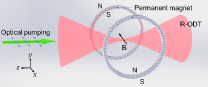
An experimental sketch of single atom manipulation in a red-detuned optical dipole trap (R-ODT) is shown in Fig. S1. The R-ODT is obtained by focusing a 1052-nm laser beam with an NA = 0.4 objective. The beam radius is 1.65 m, which is inferred from the trap frequency. We first load a single atom from cold atomic ensembles obtained by a magneto-optical trap (MOT). The trapped single atom is then cooled by polarization gradient cooling (PGC) to a temperature of approximately 10K. A magnetic field with B = 1.7 Gauss generated by permanent magnets is used to serve as a quantization axis. Next, the atom is initialized to state by a combination of a -polarized optical pumping beam, which is resonant with , and the MOT repumping light, which is resonant with . A Ramsey or spin-echo interferometer is then applied by a 9.2-GHz microwave which drives the clock transition (). The atom state is ultimately detected by counting the atom events after blowing away the atom in state with a light resonance with .
The Ramsey fringe with the 1052-nm trap laser free running and with 40-dB intensity noise added are taken, and the results are shown in Fig.S2. The data fitting by the formula in [13] gives the coherence times of and ms, respectively. The temperature of the trapped atom can be inferred by [13]
| (S6) |
and are 17.6 and 18.3 K, respectively. The temperature is slightly higher than that (10 K) measured by the release and recapture measurements. We therefore estimate the PJR by using the average temperature with K. The noise levels in Table S1 is also used for the estimation. The estimated PJRs for the free-runing and 40-dB-noise-added traps are 0.5 and 6.5 s-1, respectively.
| Condition | (kHz) | (dBc) | (kHz) | (dBc) | ||||||
|---|---|---|---|---|---|---|---|---|---|---|
|
30.3 |
|
2.7 |
|
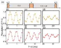
The data shown in Fig. 2 of the main text come from the fitting of the spin-echo fringe at a series time delay by sine functions. The fitted amplitude is normalized to the one with , which represents the coherence value at time . The typical spin-echo fringes are shown in Fig. S3. Figure S3(a) shows the time sequence for the spin echo interferometer. Figure S3(b)-(d) show the spin-echo fringes with laser free running and with time delays of , 100, and 200 ms, respectively. Figure S3(e)-(g) show the spin-echo fringe with 40-dB intensity noise added to the ODT laser and with time delays of , 40, and 80 ms, respectively.
III Experimental details of the single Cs atom in the 780-nm BBT
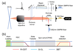
A long coherence of a single Cs atom is achieved in a blue-detuned bottle beam trap (BBT), which is built by crossing two 780-nm Laguerre-Gaussian beams [32]. Figure S4(a) shows a sketch of the experimental setup. First, a 780-nm beam in LG00 mode with waist radius mm is converted to LG01 mode by a vortex lens (HOLO/OR VL-209-M-Y-A). Then, the beam is separated into two parallel beams with equal power and orthogonal polarization by a beam displacer. The distance between the two beams was 4 mm. Finally, the two beams are focused by an NA=0.4 objective, and a BBT is obtained at the focal point. By using a total power of 9 mW, we can construct a trap with a minimum barrier height of K. The trap frequencies are kHz.
To efficiently prepare a single atom to three-dimensional (3D) motional ground states, Raman sideband cooling is applied in a combined trap composed of a red-detuned ODT (R-ODT) and a blue-detuned optical lattices (B-OL), which vastly increase the constraint in all three directions. The trap centers of the BBT and combined traps overlap spatially. The trap frequencies of the combined traps are kHz, and the corresponding Lamb-Dicke parameters are . After 50 Raman sideband cooling cycles, 82% of the Cs atoms populate their three-dimensional ground states [33].
The time sequence of the experiment is shown in Fig. S4(b). A single Cs atom is first loaded by the R-ODT from a cold atomic ensemble, which is prepared by a MOT. Then, the B-OL is switched on to compress the confinement of the loaded atom in the axial direction. A resolved Raman sideband cooling (RSC) phase is followed to prepare the atom in its 3D ZPS, and the residual phonon numbers are [33]. Next, the single atom in 3D ZPS is transferred to the BBT by adiabatically switching off the combined ODT. At this time, the atom stays in state . It is then transferred to by four microwave -pulse via the intermediate states , , and , and the total transfer efficiency is approximately 96%. Spin-echo between the Cs clock states ( and ) is performed to evaluate the decay of the coherence. The atom state is finally detected.
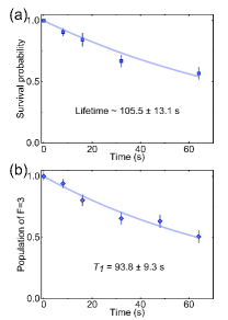
The lifetime of the trapped Cs atom and the state lifetime in BBT were also measured, and the results are shown in Fig.S6. The survival probability of the atom in the trap decreases exponentially with increasing holding time [Fig.S6(a)]. A lifetime of 105.513.1 s is then obtained by the data fitting. The atom loss is predominated by the collision of the residual gas in a vacuum. An ultrahigh vacuum (on the order of Pa) guarantees a hundred-second lifetime of a single atom. We also prepare single atoms for the state, and observe the population of state versus the holding time [Fig.S6(b)]. We finally obtain a state lifetime s, which is mainly limited by the atom lifetime.
The figures in Fig. S5 demonstrate the Ramsey fringes between states and . The pulse sequence is similar to that used in R-ODT [Fig.S5(a)]. A coherence time of ms from the Ramsey fringe was extracted. The corresponding temperature can be deduced from Eq.(S6) with nK, which agrees with the temperature of the motional ground states in the BBT. The spin-echo fringes are also taken and some of the results are shown in Fig.S7. The fringe amplitudes are extracted by fitting with sine functions. The amplitudes are normalized to that at and the decays with time delay are summarized in Fig. 4(a) of the main text.
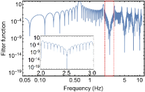
The coherence in the main text is obtained by Carr-Purcell-Meiboom-Gill (CPMG) decoupling sequence. The CPMG sequence eliminates the effects of noise at a particular frequency by periodically reversing the phase of evolution, which acts like a filter [34]. The time sequence of the CPMG used in our experiment is displayed in Fig.3(c) of the main text. In our experiment, a reversing period of 0.8 s was used. The sequences filter out the noise at frequencies Hz (), especially at the frequencies of Hz (). FigureS8 demonstrates the filter function of our CPMG sequence.
IV Photon-scattering induced decoherence
Previously, it was assumed that the coherence between two electronic ground states of an atom can be preserved via Rayleigh scattering. Here we show that even Rayleigh scattering can destroy coherence. The two ground states are denoted by and , and is coupled to an excited state by the trapping light field with a Rabi frequency and one-photon frequency detuning . The excited state has a natural line width . The Hamiltonian of the system is
| (S7) |
We then have the Heisenberg equations:
| (S8a) | ||||
| (S8b) | ||||
Assuming , we then have
| (S9) |
When , the coherence at any time is then
| (S10) |
where we set the coherence to 1 at time . is the light shift of , whose fluctuation is the variance of the DLS discussed in the main text. is the photon scattering rate, which limits the coherence time. We then have a scattering-limited coherence time
| (S11) |
Here we see that the time is limited by the overall scattering rate.