Spool-nematic ordering of dsDNA and dsRNA under confinement
Abstract
The ability of double-stranded DNA or RNA to locally melt and form kinks leads to strong non-linear elasticity effects that qualitatively affect their packing in confined spaces. Using analytical theory and numerical simulation we show that kink formation entails a mixed spool-nematic ordering of double-stranded DNA or RNA in spherical capsids, consisting of an outer spool domain and an inner, twisted nematic domain. These findings explain the experimentally observed nematic domains in viral capsids and imply that non-linear elasticity must be considered to predict the configurations and dynamics of double-stranded genomes in viruses, bacterial nucleoids or gene-delivery vehicles.
Spatial organization of genomes in viral containers Sun et al. (2010) and its physical principles Zandi et al. (2020) is an outstanding problem with a long history Pollard (1953), resulting in refined models based on cryo-electron microscopy Luque and Castón (2020), X-ray scattering techniques Khaykelson and Raviv (2020), thermodynamic osmotic pressure methodology Gelbart and Knobler (2009) and single molecule studies Smith (2011). These experiments display a range of morphologies (for a recent review see Ref. Comas-Garcia and Rosales-Mendoza (2023)). In the case of bacteriophages, high-resolution 3D reconstructions indicate inhomogeneous ordering of the encapsulated genome, with the dsRNA/DNA partitioning into ordered Ilca et al. (2019); Leforestier (2013) or disordered Leforestier and Livolant (2010) nanodomains. Similarly, measurements of DNA conformational dynamics during packaging Berndsen et al. (2014), as well as intermittent ejection dynamics Chiaruttini et al. (2010) implicate multi-domain structures. However, so far the general assumption has been that the equilibrium ground state is a single inverted spool Purohit et al. (2003); Zandi et al. (2020), or nested/linked spools Curk et al. (2019).
Mesoscopic theories Klug et al. (2005); Šiber et al. (2008); Shin and Grason (2011); Podgornik et al. (2016); Liang et al. (2019) and coarse-grained simulations of double-stranded genome packaging Kindt et al. (2001); Petrov and Harvey (2008); Rapaport (2016); Marenduzzo et al. (2009); Curk et al. (2019); Marzinek et al. (2020) are usually performed using a semiflexible polymer model that assumes linear elasticity with bending modulus nm, where is the Boltzmann constant and the temperature. However, the realistic bending response of dsDNA and dsRNA is highly non-linear due to local melting, which enables the formation of kinks. For dsDNA, kinks form beyond a critical bending torque pN nm Yan and Marko (2004); Qu et al. (2011); Qu and Zocchi (2011), and typically comprise about three melted base pairs with the reversible work required to form a kink Qu et al. (2011). Such non-linear effects can alter optimal packing configurations; in particular, a spherically-confined polymer that is able to kink exhibits increased local nematic ordering near the sphere surface Myers and Pettitt (2017); Bores and Pettitt (2020).
A general theory of a semi-flexible kinkable chain postulates an elastic free-energy density per chain length
| (1) |
with the local curvature, the free energy per kink and the local density of kinks in the chain. Here, we first perform non-equilibrium simulations to understand the packing arrangement of a kinkable, semi-flexible chain actively pushed into a spherical enclosure, and then analyze the stability of different packings using analytical theory.
A coarse-grained model that accurately describes the properties of dsDNA/RNA at small curvatures is the worm-like-chain (WLC) model; a semi-flexible polymer of length and circular cross-section with persistence length . Efficient description of nonlinear elasticity includes the kinks as regions with locally reduced persistence length . In the two-state kinkable WLC (KWLC) model Wiggins et al. (2005), molten regions behave as freely-jointed chains (), while the more accurate meltable WLC (MWLC) Yan and Marko (2004); Sivak and Geissler (2012) assigns a single-stranded persistence length to melted sections.
We model dsDNA as a discrete MWLC: a bead-spring polymer with beads of diameter . Consecutive beads are bonded by a two-body stretching term , where is the distance between two consecutive beads and the prefactor Curk et al. (2019), while excluded volume is incorporated as a WCA repulsion Weeks et al. (1971) with strength . To enable molecular dynamics (MD) simulations, we adapt the two-state MWLC model by writing it as a continuous, three–body bending interaction obtained as a canonical-ensemble superposition of a non-melted and a melted state. Assuming the states in each three-body segment are independent, and defining the Boltzmann factors and , the potential of mean force is
| (2) |
with the angle between consecutive bond vectors, and the melting penalty per bead (Fig. 1). We obtain the average kink density as the canonical average, . The MWLC model captures the non-linear elasticity of DNA bending at parameters , and reproduces the kink formation of dsDNA chain at critical torque (see Fig. LABEL:S-fig:pmf in the online supplementary information). The full () kink formation penalty at a specific base-pair is , where the last term rescales the number of kink states at bead size relative to length per nucleotide .
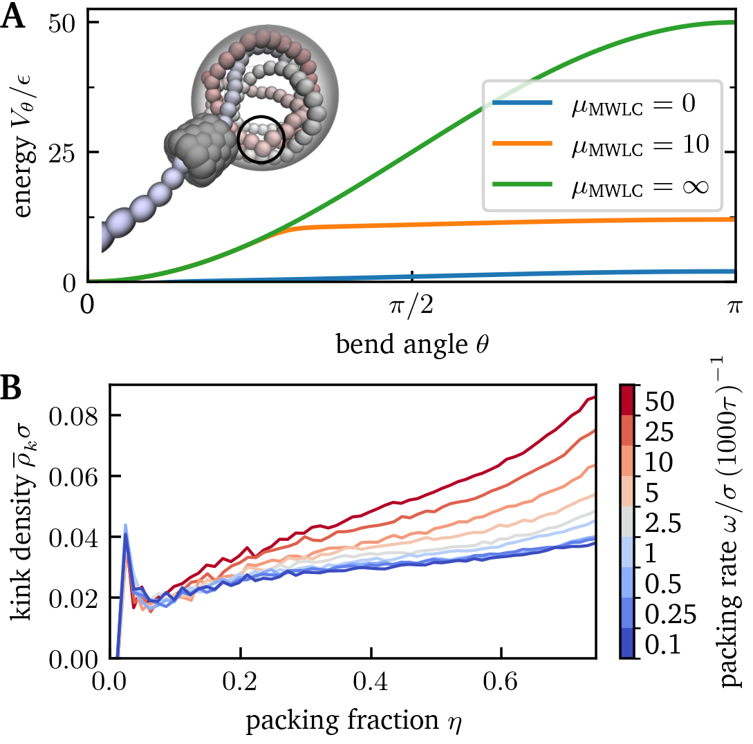
Using the MWLC model we perform MD simulations of DNA packing into a spherical capsid. Confinement is implemented as a WCA repulsion at with strength and diameter , giving an effective enclosure radius . The maximum packing density of chains is determined by hexagonal close-packing () Podgornik et al. (2016). Taking the volume of the chain relative to the maximum packed volume we define the packing fraction where the number of beads packed in the capsid.
We model the viral packing motor as a cylindrical portal of length and radius (Fig. 1A inset). The motor force operates along the portal axis on beads inside the portal, implemented as a parabolically-modulated traveling wave
| (3) |
where is the bead position in the portal (), the packing rate, the time, and the peak force. To model diffusive dynamics in an aqueous solution we apply a Langevin thermostat with damping time where is the mass of the beads, which via the Stokes-Einstein relation 111The diffusion constant of beads is , determined by the viscosity of the solvent via the Stokes-Einstein relation, resulting in the time scale . For an aqueous solution at room temperature ( Pas) and , we find results in a simulation timescale ns.
Using this setup we ran packing simulations of a 600-bead chain into a radius sphere at rates from to , with 120 independent simulations per . We observe that kinks spontaneously form with density about (Fig. 1B). Kink density increases at faster packing rates and higher packing fractions. Real viral motors pack at variable rates with the maximum rate Fuller et al. (2007a, b). The slowest we explore is ; while this is an order of magnitude faster rate than observed experimentally, we find that the order parameters converge before this value is reached, suggesting that reducing the packing rates further would not qualitatively alter the packed configurations.
Spherically-confined dsDNA is thought to arrange into spools Purohit et al. (2003); Curk et al. (2019), but kinking permits nematic ordering Myers and Pettitt (2017); Bores and Pettitt (2020), or a mixed phase of spools wrapped around a nematic core Ilca et al. (2019). To quantify spool and nematic order in our simulation configurations, we compute the order parameter tensor,
| (4) |
where is the component of either the unit binormal vector, , or the unit tangent vector, , at chain segment . The order parameter, , is the principal eigenvalue of .
Taking , gives the spool order parameter, , similar to that defined in Ref. Nikoubashman et al. (2017), while taking gives the nematic order parameter, . A mixed spool–nematic order parameter is obtained by setting,
| (5) |
where is the distance from the center-of-mass of the chain segment to a director , centered at the origin, and defines the spool–nematic boundary. In this case, must be maximized with respect to both and .
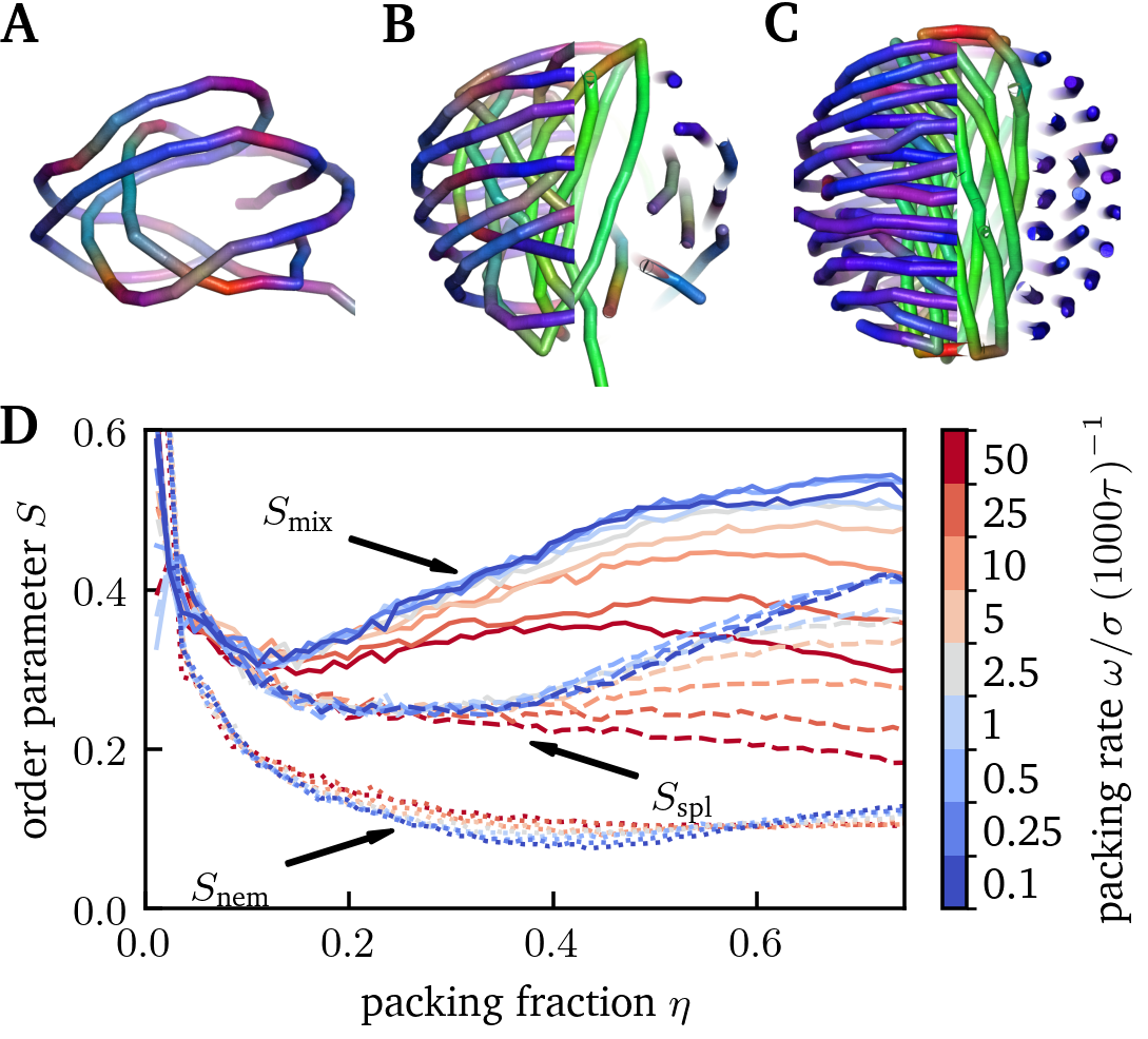
We found that the chains initially arrange into a loose spool (Fig. 2A). At intermediate packing densities (), a distinct inner domain emerges exhibiting some nematic order (Fig. 2B), which is reflected in the growth of while remains constant (Fig. 2D). Upon further packing, begins to grow while the growth of begins to slow, concomitant with a reduction of the average width of the nematic domain from to (see Fig. LABEL:S-fig:rhoc in the online SI) and slow growth in kink density (cf. Fig. 1B). We found to be of limited use because the spool domain is always more massive than the nematic domain. These trends in the order parameters agree with the observation in Fig. 2C; for dense packings, the genome adopts a mixed spool–nematic configuration.
Fast and slow packings are indistinguishable at low densities, but the growth of is dramatically reduced at faster packing rates, even falling at high densities (Fig. 2D) indicating kinetically-arrested disorder. Moreover, for the fastest packing rate , the size of the core region remains roughly constant during the time the kink density doubles from to , indicating that the chain has insufficient time to relax and grow the spool domain as packing proceeds. At slower packing rates the structures are more ordered and approach the spool–twisted-nematic configuration, while the values of all three order parameters and the kink density are well-converged among the three slowest packing rates.
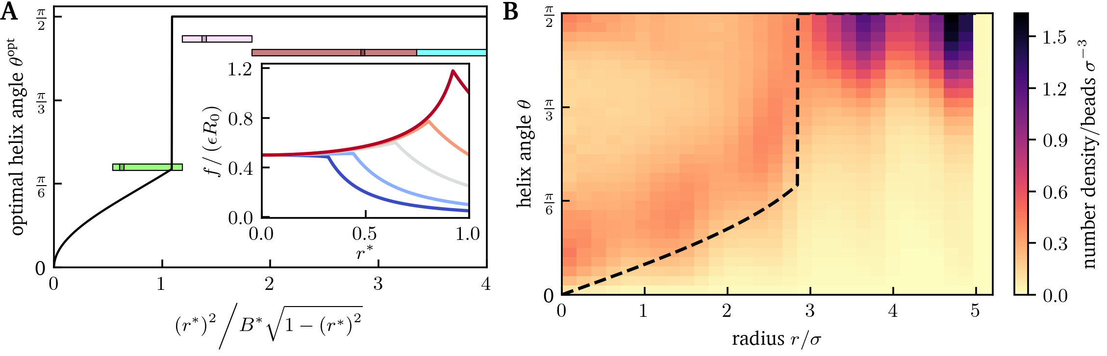
To investigate whether our packing is under thermodynamic or kinetic control, we consider an analytical theory where the chain adopts a helical configuration with radius , pitch length and slope corresponding to the helix angle . The limit corresponds to a nematic, and to a spool phase. To obtain the optimal slope, we minimize the free energy [Eq. (1)] for each helix radius , assuming that the slope of each radial shell is independent of its neighbors. The local curvature of a helix is . Assuming a kink forms whenever the chain hits the confining capsid, the kink density at radius is the reciprocal of the helix contour length, , with the maximum radius within the capsid. The optimal non-zero slope is then the real positive root of
| (6) |
where , with the ratio of bending stiffness to kink energy and . Surprisingly, we find that the optimal slope is a discontinuous function of the helix radius (Fig. 3): for small , i.e., , the optimal slope is given by
| (7) |
whereas for . At the optimal slope jumps from zero to , which, interestingly, describes a helix with an angle complementary to the magic angle . This observation implies that the outer shells form a spool (), while the inner shells form a twisted nematic domain with a large slope (Fig. 3A).
Whether the spool or the nematic core forms at low packing density depends on the ratio . favors the spool phase, whereas at the nematic core is more stable (Fig. 3A, inset). For a typical virus ( nm) and DNA parameters () we find and so predict that a spool forms initially with a transition to a nematic core at radius . Hence, the majority of the DNA should form a spool, enclosing a twisted-nematic core.
This result explains the experimental observation of a helical core structure in a dsRNA bacteriophage Ilca et al. (2019); taking and Abels et al. (2005); Hyeon et al. (2006), and assuming (the value for dsDNA), we find excellent agreement with experiment on both the critical radius and the helix angle at the transition (Fig. 3A). The analytical prediction of the helix angle also agrees with simulation results at low packing rates (, Fig. 3B), suggesting that, in the slow packing regime, our simulations are under thermodynamic control, and the packing morphology is determined by equilibrium free-energy minimization.
To obtain the full phase diagram of packing configurations we use the continuum theory of polymer nematics Shin and Grason (2011); Svenšek et al. (2010); Curk et al. (2019) where the polymer is described by a vector field . Assuming that kinks form only at the enclosure surface, and disregarding entropic contributions due to conformational fluctuations, the lowest-order non-trivial terms of the elastic free-energy functional are given by,
| (8) |
The first term is the bending term Svenšek et al. (2010); Shin and Grason (2011) with the unit tangent vector to the chain contour, while the second describes the kink density at the enclosure surface with normal vector . This expression is an integral form of Eq. (1) with prefactors and .
The optimal structure of a confined meltable filament results from competition between the elastic and melting terms in Eq. (8). For stiff polymers, kinking is preferable to bending, so they will tend to arrange into nematically-aligned straight segments with kinks at the boundaries. In contrast, flexible polymers are expected to form spool structures without kinks. To explore these competing mechanisms, we assume that the chains form a two-domain structure: an outer spool and a nematic core. The spool contains no kinks (), while the nematic core does not contribute to bending (). Assuming phases are close packed, the spool free-energy is Curk et al. (2019); Purohit et al. (2003),
| (9) |
while the nematic free energy is
| (10) |
Since the spool and the nematic core occupy disjoint volumes, and connections between domains can be neglected in the long-chain limit, the total free energy is the sum, , with the spool volume. Minimizing we find a phase diagram (Fig. 4) that is a function of two dimensionless parameters: and . The boundary delineating the pure nematic and the mixed phase is , while the boundary between the pure spool and the mixed phase is .
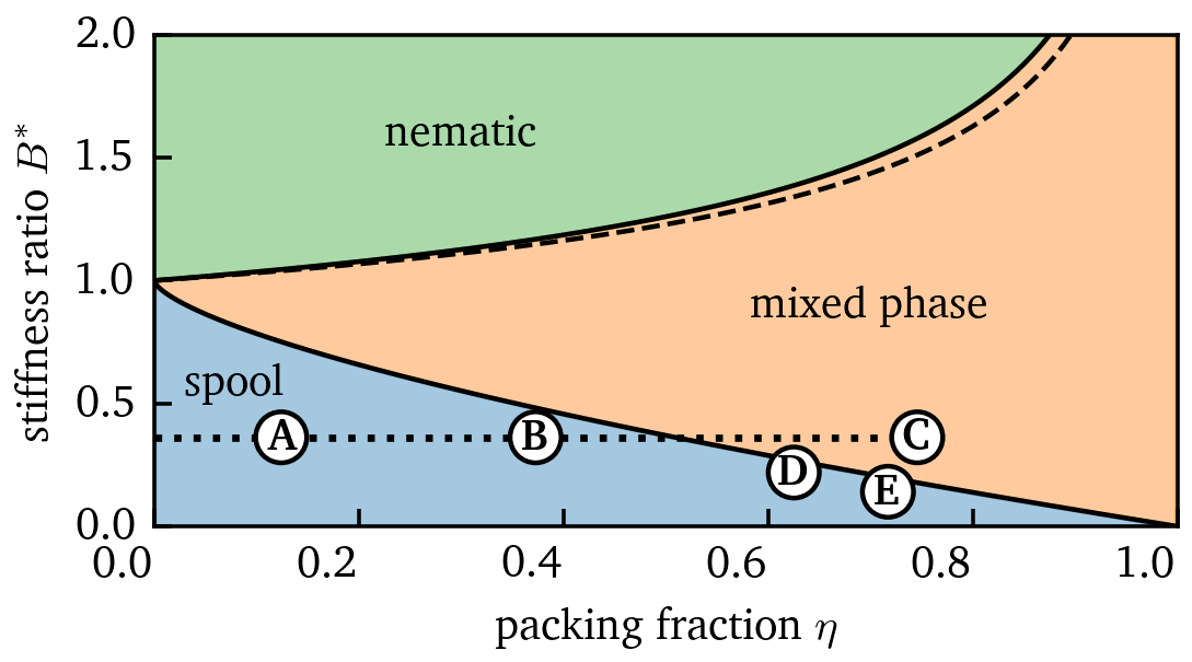
The coexistence region emerges at , growing with and dominating in the high packing fraction limit. For a typical virus, , implying a spool phase at low packing fractions, enclosing a nematic core at . This theory assumes coupled shells with no nematic twist in the core (); considering the opposite limit of free shells slightly stabilizes the nematic phase by allowing non-zero twist [Eq. (7)], but the shift in the phase boundaries is less than (dashed line in Fig. 4).
In summary, our theoretical and simulation results imply that dsDNA/dsRNA packed into a sphere adopts a spool–nematic configuration. Coexistence between an outer spool and a nematic core arises spontaneously both in packing simulations and equilibrium theory based on the minimization of elastic energy. We explored the strong and weak limits of orientational coupling, finding nearly-identical phase diagrams for a meltable chain, with the main difference being whether the nematic core exhibits non-zero twist. We expect that packing of dsDNA/dsRNA in viruses falls between these two limits, forming a large outer spool with a (twisted-)nematic core emerging at high packing densities ( for a typical nm virus). These results explain the experimental data for dsRNA packing in a bacteriophage virus Ilca et al. (2019).
We have considered packing into a pre-formed spherical capsid, but our findings are based on global free-energy minimization and thus expected to hold qualitatively for other packing situations such as DNA condensation or ordering in bacterial nucleomes. For example, kink formation and nematic ordering may explain why plasmid DNA assembles into rod-like structures Jiang et al. (2013) rather than tori Hoang et al. (2014).
Acknowledgements.
This work was supported by the Whiting School of Engineering (JHU) through startup funds, the Chinese National Science Foundation through the Key research grant 12034019, and from the Strategic Priority Research Program of the Chinese Academy of Sciences through the grant XDB33000000.References
- Sun et al. (2010) S. Sun, V. B. Rao, and M. G. Rossmann, Curr. Opin. Struct. Biol. 20, 114 (2010).
- Zandi et al. (2020) R. Zandi, B. Dragnea, A. Travesset, and R. Podgornik, Phys. Rep. 847, 1 (2020).
- Pollard (1953) E. C. Pollard, The physics of viruses (Academic Press Inc., 1953).
- Luque and Castón (2020) D. Luque and J. R. Castón, Nat. Chem. Biol. 16, 231 (2020).
- Khaykelson and Raviv (2020) D. Khaykelson and U. Raviv, Biophys. Rev. 12, 41 (2020).
- Gelbart and Knobler (2009) W. M. Gelbart and C. M. Knobler, Science 323, 1682 (2009).
- Smith (2011) D. E. Smith, Curr. Opin. Virol. 1, 134 (2011).
- Comas-Garcia and Rosales-Mendoza (2023) M. Comas-Garcia and S. Rosales-Mendoza, eds., Physical virology, From the State-of-the-Art Research to the Future of Applied Virology, Springer series in biophysics 24 (Springer International Publishing, Cham, 2023).
- Ilca et al. (2019) S. L. Ilca, X. Sun, K. El Omari, A. Kotecha, F. de Haas, F. DiMaio, J. M. Grimes, D. I. Stuart, M. M. Poranen, and J. T. Huiskonen, Nature 570, 252 (2019).
- Leforestier (2013) A. Leforestier, J Biol Phys 39, 201 (2013).
- Leforestier and Livolant (2010) A. Leforestier and F. Livolant, Journal of Molecular Biology 396, 384 (2010).
- Berndsen et al. (2014) Z. T. Berndsen, N. Keller, S. Grimes, P. J. Jardine, and D. E. Smith, PNAS 111, 8345 (2014).
- Chiaruttini et al. (2010) N. Chiaruttini, M. de Frutos, E. Augarde, P. Boulanger, L. Letellier, and V. Viasnoff, Biophysical Journal 99, 447 (2010).
- Purohit et al. (2003) P. K. Purohit, J. Kondev, and R. Phillips, Proceedings of the National Academy of Sciences 100, 3173 (2003).
- Curk et al. (2019) T. Curk, J. D. Farrell, J. Dobnikar, and R. Podgornik, Phys. Rev. Lett. 123, 047801 (2019).
- Klug et al. (2005) W. S. Klug, M. T. Feldmann, and M. Ortiz, Comput. Mech. 35, 146 (2005).
- Šiber et al. (2008) A. Šiber, M. Dragar, V. A. Parsegian, and R. Podgornik, Eur. Phys. J. E Soft Matter 26 (2008).
- Shin and Grason (2011) H. Shin and G. M. Grason, EPL 96, 36007 (2011).
- Podgornik et al. (2016) R. Podgornik, A. Aksoyoglu, S. Yasar, D. Svensek, and V. Parsegian, J. Phys. Chem. B 120, 6051 (2016).
- Liang et al. (2019) Q. Liang, Y. Jiang, and J. Z. Y. Chen, Phys. Rev. E. 100, 032502 (2019).
- Kindt et al. (2001) J. Kindt, S. Tzlil, A. Ben-Shaul, and W. M. Gelbart, Proceedings of the National Academy of Sciences 98, 13671 (2001).
- Petrov and Harvey (2008) A. Petrov and S. C. Harvey, Biophys. J. 95, 497 (2008).
- Rapaport (2016) D. C. Rapaport, Phys. Rev. E 94, 030401(R) (2016).
- Marenduzzo et al. (2009) D. Marenduzzo, E. Orlandini, A. Stasiak, D. W. Sumners, L. Tubiana, and C. Micheletti, PNAS 106, 22269 (2009).
- Marzinek et al. (2020) J. K. Marzinek, R. G. Huber, and P. J. Bond, Curr. Opin. Struct. Biol. 61, 146 (2020).
- Yan and Marko (2004) J. Yan and J. F. Marko, Phys. Rev. Lett. 93, 108108 (2004).
- Qu et al. (2011) H. Qu, Y. Wang, C.-Y. Tseng, and G. Zocchi, prx 1, 021008 (2011).
- Qu and Zocchi (2011) H. Qu and G. Zocchi, Europhysics Letters 94, 18003 (2011).
- Myers and Pettitt (2017) C. G. Myers and B. M. Pettitt, J. Comput. Chem. 38, 1191 (2017).
- Bores and Pettitt (2020) C. Bores and B. M. Pettitt, Phys. Rev. E. 101, 012406 (2020).
- Wiggins et al. (2005) P. A. Wiggins, R. Phillips, and P. C. Nelson, Phys. Rev. E 71, 021909 (2005).
- Sivak and Geissler (2012) D. A. Sivak and P. L. Geissler, J. Chem. Phys. 136, 01B615 (2012).
- Weeks et al. (1971) J. D. Weeks, D. Chandler, and H. C. Andersen, The Journal of chemical physics 54, 5237 (1971).
- Note (1) The diffusion constant of beads is , determined by the viscosity of the solvent via the Stokes-Einstein relation, resulting in the time scale . For an aqueous solution at room temperature ( Pas) and , we find .
- Fuller et al. (2007a) D. N. Fuller, D. M. Raymer, J. P. Rickgauer, R. M. Robertson, C. E. Catalano, D. L. Anderson, S. Grimes, and D. E. Smith, Journal of molecular biology 373, 1113 (2007a).
- Fuller et al. (2007b) D. N. Fuller, D. M. Raymer, V. I. Kottadiel, V. B. Rao, and D. E. Smith, Proceedings of the National Academy of Sciences 104, 16868 (2007b).
- Nikoubashman et al. (2017) A. Nikoubashman, D. A. Vega, K. Binder, and A. Milchev, Physical review letters 118, 217803 (2017).
- Abels et al. (2005) J. Abels, F. Moreno-Herrero, T. Van der Heijden, C. Dekker, and N. H. Dekker, Biophysical journal 88, 2737 (2005).
- Hyeon et al. (2006) C. Hyeon, R. I. Dima, and D. Thirumalai, The Journal of chemical physics 125 (2006).
- Svenšek et al. (2010) D. Svenšek, G. Veble, and R. Podgornik, Phys. Rev. E 82, 011708 (2010).
- Tang et al. (2011) J. Tang, G. C. Lander, A. Olia, R. Li, S. Casjens, P. Prevelige, G. Cingolani, T. S. Baker, and J. E. Johnson, Structure 19, 496 (2011).
- Jiang et al. (2013) X. Jiang, W. Qu, D. Pan, Y. Ren, J.-M. Williford, H. Cui, E. Luijten, and H.-Q. Mao, Advanced Materials 25, 227 (2013).
- Hoang et al. (2014) T. X. Hoang, A. Giacometti, R. Podgornik, N. T. T. Nguyen, J. R. Banavar, and A. Maritan, The Journal of Chemical Physics 140, 064902 (2014).