Runtime Architecture and Task Plan Co-Adaptation for Autonomous Robots with Metaplan
Abstract
Autonomous robots need to be able to handle uncertainties when deployed in the real world. For the robot to be able to robustly work in such an environment, it needs to be able to adapt both its architecture as well as its task plan. Architecture adaptation and task plan adaptation are mutually dependent, and therefore require the system to apply runtime architecture and task plan co-adaptation. This work presents Metaplan, which makes use of models of the robot and its environment, together with a PDDL planner to apply runtime architecture and task plan co-adaptation. Metaplan is designed to be easily reusable across different domains. Metaplan is shown to successfully perform runtime architecture and task plan co-adaptation with a self-adaptive unmanned underwater vehicle exemplar, and its reusability is demonstrated by applying it to an unmanned ground vehicle.
I Introduction
While operating, autonomous robots are subject to uncertainties, both from internal system factors (e.g., sensor failures) and external environment factors (e.g., unexpected obstacles). To overcome these uncertainties, robots can be designed as self-adaptive systems [1], enabling them to adapt at runtime their architecture (i.e., deactivating or activating software components and changing their parameters) and their mission execution (i.e., change the task being performed). However, as stated by Cámara et al. [2] the mutual dependencies between architecture and task plan adaptation pose a significant challenge when determining how to apply both adaptations in a coordinated manner. Thus, this paper focuses on designing a solution for runtime architecture and task plan co-adaptation (RATPA).
In the context of self-adaptive robotic systems, several works have addressed either task adaptation, architecture adaptation, or both adaptations independently [3, 4, 5, 6, 7], but only few works apply RATPA [2, 8]. Both these works define the co-adaptation problem and propose solutions for it, however, the solutions presented are not general and reusable for different robotic applications.
This paper proposes Metaplan, a planning based approach that uses off-the shelf general reasoners and knowledge about the robot’s architecture and mission to drive runtime architecture and task plan co-adaptation. Metaplan combines Metacontrol [3], a knowledge-based framework for architecture self-adaptation, with a Planning Domain Definition Language (PDDL)-based planner [9] used for simultaneous architecture and task planning, ensuring the selection of a suitable configuration for each task. This results in a general and modular solution that is only dependent on: (1) a PDDL formulation of the robot’s task planning problem, and (2) an architectural model of the robot conforming to Metacontrol’s metamodel. This explicit dependency on models makes Metaplan reusable across different applications.
Metaplan is implemented as a ROS 2-based system leveraging MROS [10, 11] and PlanSys2 [12, 13], a ROS implementation of Metacontrol and a package for handling plan generation and execution in ROS 2 respectively. It was evaluated with two different types of robots, an Unmanned Underwater Vehicle (UUV) [14], and an Unmanned Ground Vehicle (UGV) [2]. The experiments showed that Metaplan is able to perform RATPA in robotic systems, and that it is general and reusable across different applications with minimal overhead.
In summary, the contributions of this paper are:
-
•
A reusable approach for runtime architecture and task plan co-adaptation in robotic systems with minimal overhead;
-
•
Experimental results demonstrating runtime architecture and task plan co-adaptation in the SUAVE exemplar;
II Related Works
In the context of self-adaptive robotic systems, there are multiple works that have addressed either architecture adaptation or task adaptation [3, 4, 15], independent architecture and task adaptation [6, 7], or coordinated task and architecture adaptation [2, 8]. Table I presents an overview of the related works.
As a solution for architecture adaptation, Hernández et al. [16] proposed Metacontrol, a knowledge-based framework that incorporates systems with the ability to adapt their architecture at runtime. An important aspect of Metacontrol is that it uses knowledge of how the system is designed to reason when and how the system should adapt. This design choice increases Metacontrol’s reusability, since it is only required to modify the knowledge base in order to apply it to different applications. Metacontrol was demonstrated with different robotics applications, such as mobile base navigation and underwater vehicles [3, 16, 17, 18, 19].
Purandare et al. [7] proposed the CICADA framework to enable Unmanned Aerial Vehicles (UAVs) to recover from misconfiguration-related flight instability. This is achieved by adapting the UAVs’ flight controller configuration at runtime to a safe baseline configuration or by adapting the task it is performing. Although CICADA is able to perform both architecture and task adaptation, they are performed independently. In relation to reusability, CICADA was specifically designed to handle misconfiguration-related flight instability in UAVs, and does not generalize to other applications.
Valner et al. [6] proposed the TeMoto software architecture to address the challenges of dynamic task and resource management. Similarly to CICADA, TeMoto is able to handle architecture and task adaptation independently, but not in a coordinated manner. In terms of reusability, TeMoto is task independent, but it requires the adaptation logic to be manually implemented for each managed resource.
RATPA was first addressed by Braberman et al. [8] with the MORPH reference architecture. Although MORPH is proposed as a solution for architecture and task plan co-adaptation, it is only demonstrated on a conceptual level. This makes it difficult to evaluate the feasibility of applying MORPH to robotic systems at runtime, and to compare it to other methods for robotics adaptation.
Cámara et al. [2] present a framework for architecture and task co-adaptation based on probabilistic model checking. Their approach consists of using an explicit model of the robot with a probabilistic model checker to synthesize all possible reconfiguration plans, including their associated cost, and to find the most suitable task plan for the robot, including the required reconfiguration plans. Some limitations of their approach are that task planning does not take into account that an action might become unavailable when there is no architectural configuration available to solve it. Furthermore, their task planning solution is specific for navigation on a graph-like map, thus applying it to a new task planning scenario requires extensive changes.
In the current state of the art, as far as the authors are aware, the only solution available for architecture and task plan co-adaptation is the one proposed by Cámara et al. [2]. However, their solution is not general enough to be applied to different applications without modifications. Therefore, this work aims to fill this gap by proposing Metaplan.
III Metacontrol Background
Metacontrol adheres to the principle of separation of concerns for self-adaptive systems into a managed subsystem and a managing subsystem [1]. Where the managed subsystem is responsible for domain concerns, in this case, the robotic application, and the managing subsystem is responsible for adapting the managed subsystem. Its reasoning cycle follows the MAPE-K loop [20]. It monitors the relevant parameters of the managed subsystem and the environment, analyzes whether the managed subsystem configuration fulfills its requirements, reconfigures when necessary. All these steps are performed in interaction with its knowledge base (KB).
Metacontrol’s KB conforms to the Teleological and Ontological Model for Autonomous Systems (TOMASys) metamodel [16]. In short, TOMASys captures engineering knowledge of how the system is designed, its possible configuration alternatives, and how attributes of the managed system or environment relate to the selection of a configuration. A simplified version of TOMASys with the required concepts for this work can be seen in Figure 1. The design time elements are specified by the designer of the adaptation logic, and they are static throughout the system operation. The runtime elements are dynamically specified by the system during its operation. Throughout this work, TOMASys elements will be written with this font.
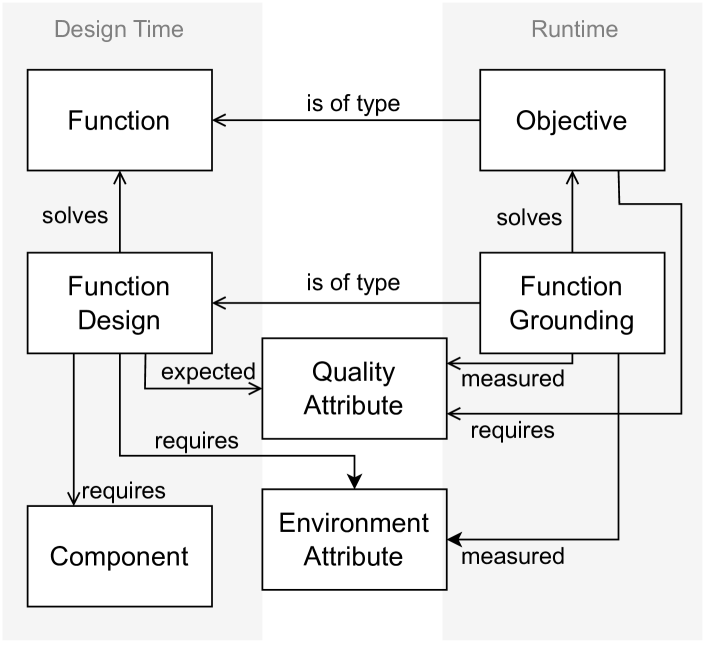
The design time elements of TOMASys are: function, function design, component, qualitty attribute, and environment attribute. A function represents a functionality of the managed subsystem, e.g., navigation. A function design is a particular solution for a function, in other words, each function design represents a possible configuration that can be selected by Metacontrol, e.g., a particular navigation algorithm. A component represents a hardware or software component of the system that is required by a function design, e.g., a sonar. A quality attribute represents an attribute of the system, e.g., battery level. And a environment attribute represents an attribute of the environment, e.g., water visibility. Specific quality attribute or environment attribute values can be set as requirements for function designs, e.g., a certain navigation algorithm can only be used if the battery level is above .
The runtime elements of TOMASys are: objective and function grounding. An objective represents the functions of the system that are currently required, e.g., while performing a navigation task the robot has an objective of the navigation function type. A function grounding represents the current function design that is deployed to solve an objective.
In addition to the architectural model, the KB contains rules that are reasoned over at runtime to evaluate the status of the system and decide when adaptation is required, i.e., a rule indicating that a function grounding is in error when the measured value of a quality attribute violates its requirement.
IV Metaplan
Metaplan is designed to perform the role of a managing subsystem. Metaplan assumes that the managed subsystem is component-based and task oriented. The former means that the manged subsystem is composed of multiple loosely coupled software components that can be activated or deactivated at runtime. The latter means that the managing subsystem is designed to handle tasks, which are realized by a sequence of actions. The managed subsystem is designed to accomplish these actions by activating the corresponding components.
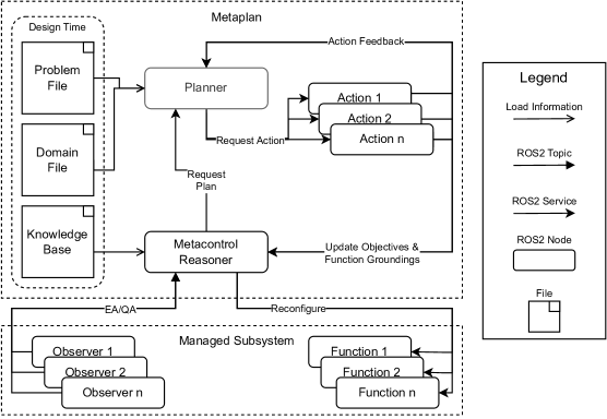
The architecture of Metaplan is depicted in Figure 2. Its main components are the Planner and the Metacontrol Reasoner. The Metacontrol Reasoner is responsible for analyzing runtime information to decide when the robot needs to adapt, which configurations are currently available, and executing the reconfigurations selected by the Planner by activating and deactivating Function nodes of the managed subsystem. The Planner is responsible for planning the actions of the robot and its respective required configurations, and informing Metacontrol about the selected reconfiguration plans. The planner is based on PDDL, and its planning problem is defined in the Domain and Problem files.
To reach its goal state, Metaplan generates a task plan consisting of a sequence of actions, and selects the required configuration to accomplish each action. These actions correspond to one or more functions of the robot expressed in the KB, and the configurations for each action correspond to the selected function designs. When an action finishes execution, the next action of the task plan starts execution.
Whenever a function design becomes (un)available or an objective is in error, Metaplan generates a new task plan. This allows for Metaplan to adapt the system configuration using the updated available function designs, and could adapt the task plan by generating a different plan, thereby achieving runtime architecture and task plan co-adaptation.
The remainder of this section details Metaplan’s architecture, the design time activities required to configure Metaplan for a robotic scenario, and its runtime behavior.
IV-A Design time activities
To apply Metaplan to a specific application, it is necessary to create a KB containing an architectural model of the robot, and define the robot task planning problem with PDDL in a Domain and Problem file.
IV-A1 Knowledge Base
The KB captures information about the robot’s architecture and its variants, it is modeled conforming to the TOMASys metamodel (see section III). The KB is reusable for different applications within the same domain, that is, for the same robot with the same architecture in a similar environment.
IV-A2 Domain File
The Domain File defines which actions are available, and their preconditions and effects. The Domain File contains a generic description of the actions the robotic system is able to perform, which conform to the functions defined in the KB. This means that the Domain File can be used for different uses within the same domain, i.e., a Domain File containing a description of a mobile robot used in a hospital environment can be used for multiple missions for that same robot in the same environment.
An important design requirement for each action is that it needs a precondition stating which functions it requires, and that there need to be function designs available to solve these functions. The PDDL formulation of these requirements can be seen in Listing 1. Assume action1 is one of the actions the system can perform. The action would first need to be linked to an action object (line 1). This action object requires a function (line 2). This function is solved by a function design (line 3), which is available (line 4). This allows the PDDL planner to select an action to be executed, together with a suitable configuration.
IV-A3 Problem File
The Problem File defines the initial state and goal state of the planning problem. This definition is specific to the mission of the robot and only applies within this context.
An important design requirement for Metaplan is information on which actions require which functions. The PDDL formulation of this requirement can be seen in Listing 2. The object specifying action1 (line 1) and which functions it requires (line 2) need to be created by the user.
IV-B Runtime behavior
This section explains the runtime behavior of the components of Metaplan depicted in Figure 2. Upon startup, the information from the KB, the Domain File, and the Problem File is loaded by the corresponding nodes.
The Metaplan loop starts by monitoring the environment and quality attributes. This information is passed to the Metacontrol reasoner. The Metacontrol Reasoner loop can be seen in Algorithm 1. First (line 1), the Metacontrol Reasoner updates the Knowledge Base with information on the environment and quality attributes received from the Observer nodes. Next (line 2), the KB is analyzed with automatic reasoning using the KB rules to find which function designs are available and whether any objectives are in error. If the available function designs have changed since the last iteration of the loop or there are objectives in error, then the new function designs are sent to the Planner and a new plan is requested (lines 3-5). Lastly (line 6), the old function designs are updated with the new function designs for the next iteration.
A plan request triggers the planner to generate a new plan. Algorithm 1 gives a step-by-step overview of how this is done. First (line 1), the Problem File (PF) is updated with the function designs that are available. Afterwards (line 2), the Planner generates an action plan using the Problem File and Domain File (DF) consisting of a list of actions in sequence. These actions are then executed one by one, until the whole action plan is finished (lines 3-5).
An action is requested together with information on which function designs (i.e., which configuration) should be used to solve the functions required by the action. At the start of execution of an action, the objectives and function groundings of the Metacontrol Reasoner are updated. This, in turn, triggers the managed subsystem to use the Function nodes corresponding to the required functions and to use the updated function groundings.
V Evaluation
Two experiments were performed to demonstrate the reusability and feasibility of Metaplan. The first experiment consisted of using Metaplan to design a solution for the UGV scenario described by Cámara et al. [2]. The goal of this experiment was to demonstrate the reusability and minimal overhead required for Metaplan following the design activities presented in subsection IV-A. The second experiment consisted of applying Metaplan to a simulated unmanned underwater vehicle performing a pipeline inspection mission. The goal of this experiment was to demonstrate the feasibility to use Metaplan with robots.
V-A UGV scenario
In this scenario, the UGV has to navigate from an initial position to a goal position in the least amount of time and as safely and efficiently as possible. During its operation, the robot encounters obstacles and changing lighting conditions, to which it needs to adapt its architecture and task plan.
The robot has three distinct algorithms for localization: AMCL, MRPT, and Aruco. Each of these algorithms require input from different sensors, AMCL and MRPT require input from a lidar or a kinect, and the Aruco algorithm requires camera input. However, the camera can only be used in low light conditions in combination with a flashlight.
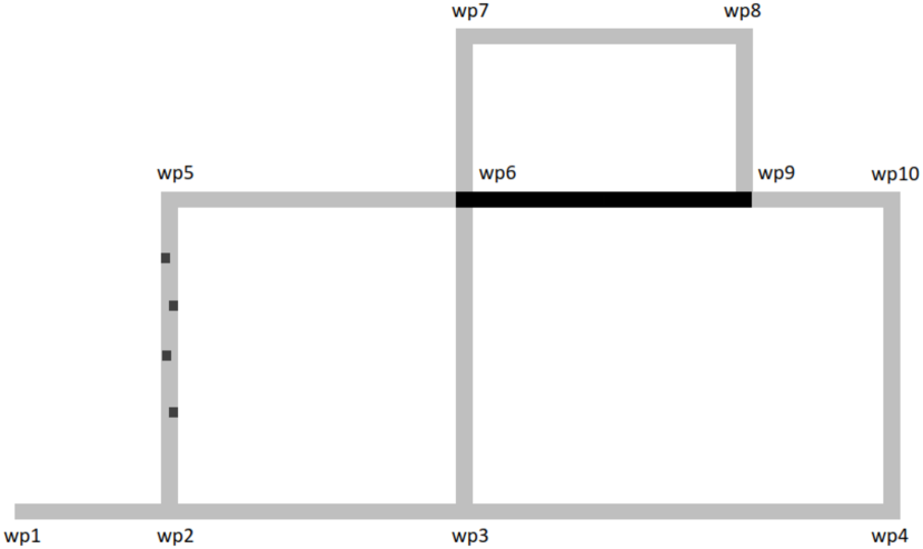
The robot navigates in a graph-like environment, with vertices representing intersections, and edges representing corridors. The robot knows the layout of the environment, and which corridors are dark or contain obstacles. A simplified version of the map of the environment can be seen in Figure 3. Note that the corridor between wp6 and wp9 is dark, and the corridor between wp2 and wp5 contains obstacles. At runtime, the robot needs to decide which paths to take and which configuration to use for each path.
The setup for the original experiment is not publicly available, thus this work is only simulated at the task and configuration level.
V-A1 Design time activities
To apply Metaplan to this case, the design activities described in subsection IV-A are followed, and they are described below.
Knowledge Base
The only task the UGV is able to perform is navigating from point A to B, and the only variability available is which localization algorithm in combination with which sensors to use. Thus, only a localization function called f_localization is included in the ontology. Each combination of the available localization algorithms with the available components is represented as a distinct function design requiring specific components, as can be seen in the first two columns of Table II.
Each function design has an expected battery usage that is represented as a quality attribute named QA_battery_usage. Furthermore, each function design requires a minimum level of the environment attributes that represent how safe a path is and the lighting condition of the environment, respectively, EA_safety and EA_light. The specific values for the quality and environment attributes associated to each function design can be seen in the last three columns of Table II.
| Function Design | Required Components | QA | EA | ||||||
|
|
|
|||||||
| fd_AMCL_lidar | c_lidar | 4 | 0.4 | 0 | |||||
| fd_AMCL_kinect | c_kinect | 2 | 1.0 | 0 | |||||
| fd_MRPT_lidar | c_lidar | 6 | 0.3 | 0 | |||||
| fd_MRPT_kinect | c_kinect | 4 | 0.9 | 0 | |||||
| fd_aruco | c_camera | 7 | 0.7 | 0 | |||||
| fd_aruco_with_light |
|
10 | 0.7 | 1 | |||||
Domain File
Three distinct move actions are defined, one for each type of corridor, e.g., move, move_with_obstacle, and move_dark.
Problem File
The Problem File defines the initial state and goal state of the robot. It also contains information about all corridors between two waypoints and the type of each corridor, e.g., dark corridor or corridor with obstacles. Furthermore, the problem file also contains information on which functions the move actions require, the current location of the robot, the battery level of the robot, and the goal location of the robot.
V-A2 Results
The robot Metaplan updates the availability of the function designs for each corridor comparing the EA_light and EA_safety levels specified in the KB (Table II) with the required levels corresponding to the environment map (Figure 3). The measured EA_light is 0 for the dark corridors and 1 for the other corridors, and the measured EA_safety is 0.8 for the corridors with obstacles and 0 for the other corridors. Note that the measured safety indicates the level of safety required to pass through that corridor, so Metaplan needs to select a function design with an EA_safety of more than 0.8 to pass through those corridors.
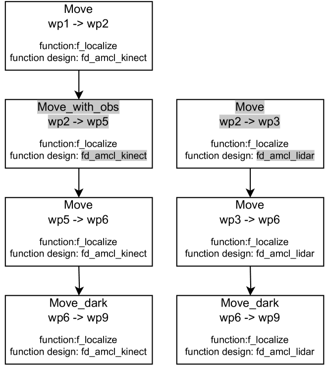
For this experiment, the battery level is initially set to 100% and the robot has to navigate from wp1 to wp9. The first plan generated by the robot is presented on the left side of Figure 4. The robot selects fd_amcl_kinect, since enough battery is available to select this function design. Afterward, the robot encounters a corridor with obstacles and does not need to adapt its configuration, since fd_amcl_kinect meets the required safety levels.
When the robot reaches wp2, fd_amcl_kinect and fd_mrpt_kinect are set to be unavailable to simulate a failure of c_kinect. This requires the robot to adapt its task plan, since no function designs are available for navigating through an obstacle corridor. Furthermore, the robot is also required to adapt its architecture, since fd_amcl_kinect is unavailable. This results in the task plan presented on the right side of Figure 4. Metaplan successfully finds a new plan avoiding the obstacle corridor and passing through wp3 instead, and adapts its configuration to fd_amcl_lidar. After this, the robot can fulfil the rest of the mission without needing replanning.
The reusability of Metaplan can be demonstrated with the following modifications of the UGV scenario.
Modification 1
Suppose that the UGV’s initial position, goal position, or the map layout is changed. In comparison to the original scenario, only the PDDL problem file needs to be modified by changing the variables corresponding to the initial position, goal position, or map layout.
Modification 2
Suppose that the move action in a corridor obstacle is altered to use more battery. In comparison to the original scenario, only the PDDL domain file needs to be modified by changing the values of the required battery level precondition and the battery consumption effect in the move action for the corridor with obstacles.
Modification 3
Suppose that the implementation of the MRPT localization algorithm is improved, thus its required safety levels can be changed. In comparison to the original scenario, only the KB needs to be modified by changing the values of the required EA_safety for fd_mrpt_kinect and fd_mrpt_lidar.
V-B UUV pipeline inspection
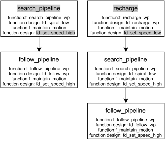
This scenario consists of a UUV that is deployed to inspect a pipeline as fast as possible, while ensuring it has enough battery available to complete the inspection. The UUV has a set of actions available with which it can achieve its mission. These actions are search pipeline, follow pipeline, and recharge. If at any time the battery falls below a critical level, the UUV needs to go to the charging station and recharge. Each action requires a different set of functions and therefore different configurations of the UUV.
The UUV needs to be able to handle two types of uncertainties: changing water visibility and a sudden drop in battery level. This requires the UUV to adapt both its architecture, to use less battery, and its task plan, to go to the charging station before fulfilling the rest of the mission.
The UUV is able to configure its speed to low, medium, or high. A high speed allows the UUV to reach its goal state faster, however, it consumes more energy. The robot is also able to adjust the height at which it searches for the pipeline. There are three different heights the UUV can search at, namely low, medium, and high. A high search height allows the robot to detect the pipeline faster, however the UUV will not be able to see the pipeline if the water visibility is low.
V-B1 Results
At the beginning of execution of the UUV’s mission, an initial plan specifying a sequence of actions and required configurations was generated, which can be seen on the left side of Figure 5. The initial plan requires the UUV to first search for the pipeline and, when found, follow the pipeline. When a simulated sudden drop in battery level is inserted, the UUV is required to adapt and generates a new plan, which can be seen on the right side of Figure 5. The UUV changes its configuration by adjusting its speed to low and changes its plan by first going to the recharge station.
This experiment was successfully executed in simulation using the SUAVE exemplar [14], demonstrating the feasibility of applying Metplan at runtime to a ROS 2-based robotic systems. A video of the simulation showcasing the RATPA behavior can be seen here.
VI Conclusions and Future Works
This work presented Metaplan as a reusable solution for architecture and task plan co-adaptation. Metaplan uses a PDDL-based planner for task and configuration planning, and Metacontrol to capture, analyze, and manage architectural knowledge. This resulted in a general and reusable framework since it only depends on a PPDL formulation of the robot’s task planning problem, and in an architectural model of the robot conforming to the TOMASys metamodel, as detailed in subsection IV-A. The experiments performed provided further evidence to the reusability claim by applying Metaplan to two distinct robotic applications, and demonstrated the feasibility of applying it to robotic systems at runtime.
Future works include: evaluating Metaplan’s time performance and how it scales in more complex scenarios; capturing the dependency between tasks and functionalities in TOMASys instead of in the PDDL formulation, to make it more general and reusable.
References
- [1] D. Weyns, An Introduction to Self-adaptive Systems: A Contemporary Software Engineering Perspective. John Wiley & Sons, 2020.
- [2] J. Cámara, B. Schmerl, and D. Garlan, “Software architecture and task plan co-adaptation for mobile service robots,” in Proceedings of the IEEE/ACM 15th International Symposium on Software Engineering for Adaptive and Self-Managing Systems, pp. 125–136, 2020.
- [3] E. Aguado, Z. Milosevic, C. Hernández, R. Sanz, M. Garzon, D. Bozhinoski, and C. Rossi, “Functional self-awareness and metacontrol for underwater robot autonomy,” Sensors, vol. 21, no. 4, p. 1210, 2021.
- [4] M. Molina and P. Santamaria, “Behavior coordination for self-adaptive robots using constraint-based configuration,” arXiv preprint arXiv:2103.13128, 2021.
- [5] B. H. Cheng, R. J. Clark, J. E. Fleck, M. A. Langford, and P. K. McKinley, “Ac-ros: assurance case driven adaptation for the robot operating system,” in Proceedings of the 23rd ACM/IEEE International Conference on Model Driven Engineering Languages and Systems, pp. 102–113, 2020.
- [6] R. Valner, V. Vunder, A. Aabloo, M. Pryor, and K. Kruusamäe, “Temoto: A software framework for adaptive and dependable robotic autonomy with dynamic resource management,” IEEE Access, 2022.
- [7] S. Purandare, U. Sinha, M. N. A. Islam, J. Cleland-Huang, and M. B. Cohen, “Self-adaptive mechanisms for misconfigurations in small uncrewed aerial systems,” in 2023 IEEE/ACM 18th Symposium on Software Engineering for Adaptive and Self-Managing Systems (SEAMS), pp. 169–180, 2023.
- [8] V. Braberman, N. D’Ippolito, J. Kramer, D. Sykes, and S. Uchitel, “Morph: A reference architecture for configuration and behaviour self-adaptation,” in Proceedings of the 1st international workshop on control theory for software engineering, pp. 9–16, 2015.
- [9] M. Ghallab, A. Howe, C. Knoblock, D. Mcdermott, A. Ram, M. Veloso, D. Weld, and D. Wilkins, “PDDL—The Planning Domain Definition Language,” 1998.
- [10] C. H. Corbato, D. Bozhinoski, M. G. Oviedo, G. van der Hoorn, N. H. Garcia, H. Deshpande, J. Tjerngren, and A. Wasowski, “Mros: Runtime adaptation for robot control architectures,” arXiv preprint arXiv:2010.09145, 2020.
- [11] “Mros package.” https://github.com/meta-control/mc_mros_reasoner. Accessed: 2023-09-13.
- [12] F. Martín, J. G. Clavero, V. Matellán, and F. J. Rodríguez, “Plansys2: A planning system framework for ros2,” in 2021 IEEE/RSJ International Conference on Intelligent Robots and Systems (IROS), pp. 9742–9749, IEEE, 2021.
- [13] “Plansys2 package.” https://github.com/PlanSys2/ros2_planning_system. Accessed: 2023-09-13.
- [14] G. R. Silva, J. Päßler, J. Zwanepol, E. Alberts, S. L. T. Tarifa, I. Gerostathopoulos, E. B. Johnsen, and C. H. Corbato, “Suave: An exemplar for self-adaptive underwater vehicles,” in 2023 IEEE/ACM 18th Symposium on Software Engineering for Adaptive and Self-Managing Systems (SEAMS), pp. 181–187, 2023.
- [15] Y. Carreno, J. S. Willners, Y. R. Petillot, and R. P. Petrick, “Situation-aware task planning for robust auv exploration in extreme environments,” in Proceedings of the IJCAI Workshop on Robust and Reliable Autonomy in the Wild, 2021.
- [16] C. Hernández, “Model-based self-awareness patterns for autonomy,” 2013.
- [17] C. Hernández, J. Bermejo-Alonso, and R. Sanz, “A self-adaptation framework based on functional knowledge for augmented autonomy in robots,” Integrated Computer-Aided Engineering, vol. 25, no. 2, pp. 157–172, 2018.
- [18] C. Hernandez Corbato, Z. Milosevic, C. Olivares, G. Rodriguez, and C. Rossi, “Meta-control and self-awareness for the ux-1 autonomous underwater robot,” in Iberian Robotics conference, pp. 404–415, Springer, 2019.
- [19] D. Bozhinoski, M. G. Oviedo, N. H. Garcia, H. Deshpande, G. van der Hoorn, J. Tjerngren, A. Wasowski, and C. H. Corbato, “Mros: runtime adaptation for robot control architectures,” Advanced Robotics, vol. 36, no. 11, pp. 502–518, 2022.
- [20] P. Horn, “Autonomic computing: Ibm’s perspective on the state of information technology,” 2001.
- [21] G. Antoniou and F. van Harmelen, Web Ontology Language: OWL, pp. 67–92. Berlin, Heidelberg: Springer Berlin Heidelberg, 2004.
- [22] A. SWRL, “Semantic web rule language combining owl and ruleml,” W3C Member Submission (May 21, 2004), http://www. w3. org/Submission/SWRL/(last visited March 2011), 2004.
- [23] E. Sirin, B. Parsia, B. C. Grau, A. Kalyanpur, and Y. Katz, “Pellet: A practical owl-dl reasoner,” Journal of Web Semantics, vol. 5, no. 2, pp. 51–53, 2007.