Demonstration of fault-tolerant Steane quantum error correction
Abstract
Encoding information redundantly using quantum error-correcting (QEC) codes allows one to overcome the inherent sensitivity to noise in quantum computers to ultimately achieve large-scale quantum computation. The Steane QEC method involves preparing an auxiliary logical qubit of the same QEC code used for the data register. The data and auxiliary registers are then coupled with a logical CNOT gate, enabling a measurement of the auxiliary register to reveal the error syndrome. This study presents the implementation of multiple rounds of fault-tolerant Steane QEC on a trapped-ion quantum computer. Various QEC codes are employed, and the results are compared to a previous experimental approach utilizing flag qubits. Our experimental findings show improved logical fidelities for Steane QEC. This establishes experimental Steane QEC as a competitive paradigm for fault-tolerant quantum computing.
I Introduction
Quantum computing has the potential to outperform classical machines by exploiting superposition and entanglement. To achieve this goal of enhanced computational capabilities, it is crucial to safeguard quantum information, e.g. by encoding it into stabilizer codes that protect against environmental and operational noise. By repeatedly measuring the stabilizer generators, we can detect noise without disrupting the logical computational state. The error and its location within the register are mapped onto the results of the stabilizer measurements, also referred to as error syndrome. We must prevent the spread of harmful errors by following the principles of quantum fault tolerance to conduct quantum computation on the encoded level while maintaining the expected scaling of logical error rates with physical error rates. This requirement implies experimental challenges in fault-tolerant (FT) logical state preparation, FT logical gates, and FT error correction.
Recent progress in achieving error-corrected universal quantum computation has been made through the development of FT QEC components in leading hardware architectures. In superconducting systems, significant strides have been made towards operating Kitaev’s surface code, resulting in an operation fidelity that exceeds the break-even point Google Quantum AI (2021); Krinner et al. (2022); Zhao et al. (2022); Google Quantum AI (2023). Additionally, FT magic state preparation has been demonstrated in a superconducting experiment with fidelity beyond break-even Gupta et al. (2023). Ion-trap experiments have demonstrated FT stabilizer readout Hilder et al. (2022), FT control of single logical qubits Egan et al. (2021), and FT repetitive QEC cycles Ryan-Anderson et al. (2021), with subsequent efforts aimed at implementing universal FT logical gate sets Postler et al. (2022); Ryan-Anderson et al. (2022). Meanwhile, practical experimental benefits of fault tolerance have been demonstrated in error-detecting codes, such as FT non-Clifford gates on multiple logical qubits in both superconducting and trapped-ion devices Menendez et al. (2023), FT one-bit addition as a small logical algorithm on three logical qubits Wang et al. (2023), the realization of Grover search utilizing encoded qubits in a trapped-ion device Pokharel and Lidar (2022), and the very recent demonstration of a larger logical quantum processor with neutral atoms Bluvstein et al. (2023).
The backbone of the successful operation of a fault-tolerant quantum processor is an efficient implementation of QEC cycles. Steane QEC minimizes the coupling between data and auxiliary qubits and therefore also perturbations of the data register. Thus it is a promising candidate for the efficient extraction of error syndromes on scalable error-correcting codes.
II Fault-tolerant quantum error correction
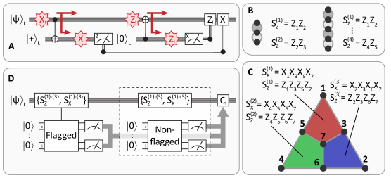
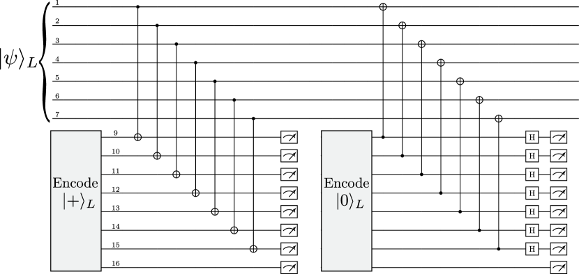
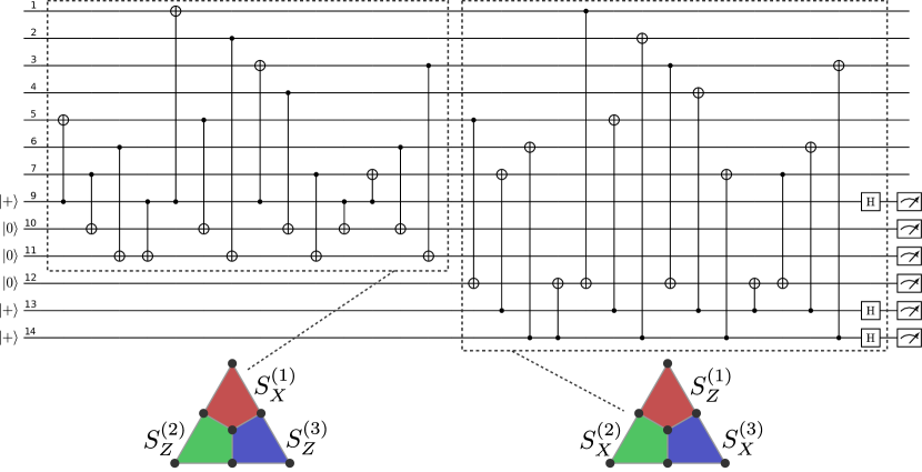
Given operations acting on logically encoded qubits, such as initialization, gate operations, and measurements, have to be constructed in a way that prevents dangerous propagation of errors. An error configuration is dangerous when an otherwise correctable number of errors spreads via entangling gates and turns into an error supported on a number qubits (referred to as the weight of the error) beyond the number of errors the code can correct. A circuit where this is precluded by design is called a fault-tolerant implementation and hence we refer to the corresponding operations as fault-tolerant. In particular, this applies to the QEC block itself, where the necessary coupling to auxiliary qubits unavoidably feeds back to the data qubits. Any coupling can then potentially induce errors if the auxiliary qubit or the coupling itself is faulty. A method to extract the error syndrome, which minimizes the interaction between the logical data qubit(s) and the auxiliary qubit(s), was formulated by Steane Steane (1997). The key idea is to prepare an auxiliary logical qubit using the same code as the data qubit and to couple both logical qubits via a transversal logical CNOT gate, i.e. in a bit-wise manner. This guarantees that if any single physical operation is faulty, at most one error per encoded logical qubit block is introduced. Specifically, first, an auxiliary logical qubit is prepared in a superposition of its basis logical states and a transversal CdataNOTaux is applied, as illustrated in Fig. 1A. In the error-free case, the CNOT will act trivially on both encoded qubits as . However, if a single bit-flip is present on the th qubit comprising the logical data qubit (denoted as ), this will be copied onto the th qubit comprising the logical auxiliary qubit (denoted as ) as
| (1) | ||||
The transversal CNOT gate is FT by construction since it introduces at most one error on each encoded block. The entire circuit is therefore FT if one additionally verifies that only a correctable number of errors is present on the auxiliary logical qubit. The syndrome can then be reconstructed from the outcomes of the projective measurement of the auxiliary logical qubit in a single shot. One can identify the appropriate recovery operation based on a decoder such as the lookup table for the seven-qubit color shown as Tab. 1 in Appendix A.1. Just as an auxiliary logical qubit in detects propagated -errors, it detects propagated -errors when prepared in and acted upon with a transversal CauxNOTdata in a second half-cycle. In this second half-cycle -errors are copied from the data qubit to the auxiliary qubit such that measuring the auxiliary qubits reveals the entire -syndrome simultaneously, just as the first half-cycle reveals the entire -syndrome. This Steane-type QEC is to be seen in contrast to measuring each stabilizer individually, where due to fault tolerance requirements one has to resort to either verified Greenberger–Horne–Zeilinger (GHZ) states or flag schemes for the auxiliary qubits Shor (1996); Chamberland and Beverland (2018). Moreover, the syndrome measurement has to be repeated for specific measurement outcomes to avoid single faults leading to high-weight errors, which requires the conditional execution of circuits. In our experiment and simulation, in order to benchmark against the Steane-type QEC, we implement the flagged syndrome extraction protocol of Reichardt (2020), which was previously realized experimentally in Ryan-Anderson et al. (2021). The circuits that are used in the implementation are shown in Fig. A4.
In this article, we report the implementation of Steane syndrome extraction in a trapped-ion experiment. Central to the implementation of Steane QEC is the transversal logical CNOT, which in our experiment can be performed between all qubits owing to all-to-all qubit connectivity. We employ this to perform single-shot syndrome extraction on different error-correcting codes. As a first step, we investigate the bit-flip and phase-flip repetition codes with code distances and each. While the repetition code protects only against either Pauli- or - errors, the syndrome extraction procedure is the same as for leading QEC codes such as surface and color codes. We can therefore experimentally explore the scaling of Steane quantum error correction for codes of increasing distance. Furthermore we demonstrate Steane syndrome extraction for a complete quantum error correcting code by applying it to the seven-qubit color code. We perform up to five and three full cycles of syndrome extraction for the repetition code and seven-qubit color code, respectively.
III Experimental setup
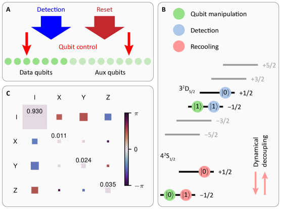
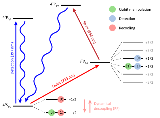
All experimental results presented in this manuscript are implemented in a trapped-ion quantum processor. Sixteen 40Ca+ ions are trapped in a macroscopic linear Paul trap, where the electronic state of the ions is controlled via laser pulses, as illustrated in Fig. 2A. Each ion encodes one qubit in the electronic states and (see Fig. 2B) connected via an optical quadrupole transition at a wavelength of . Coulomb interaction between the ions gives rise to collective motional modes of the ions, which are used to mediate entangling operations between any desired pair of qubits. The available universal gate set and its error characteristics are described in more detail in Appendix C.
For the repeated application of QEC blocks to encoded qubits it is necessary to have the ability to extract the error syndrome by performing measurements on a subset of qubits. Measurements on these auxiliary qubits are designed in a way that minimizes the perturbation of the logical information stored in the data qubits. Furthermore it is beneficial to have the capability of reusing measured qubits by reinitializing them to a defined state in the computational subspace, especially with the limited quantum register sizes of noisy intermediate-scale quantum devices. Viable approaches to implement these procedures in trapped-ion quantum processors are introducing a second atomic species Negnevitsky et al. (2018); Pino et al. (2021); Erickson et al. (2022), or moving ions to a distinct region of the trap Hilder et al. (2022); Zhu et al. (2023) for mid-circuit measurements allowing state readout of auxiliary qubits while keeping data qubits unperturbed. In this work we make use of multiple Zeeman-sublevels in the states and (see Fig. 2) for the implementation of mid-circuit measurements and subsequent reinitialization Riebe et al. (2008); Monz et al. (2016); Manovitz et al. (2022).
The first step of this procedure is the detection of the auxiliary qubits by electron shelving Schindler et al. (2013). All data qubits are encoded in the states shown as blue symbols in Fig. 2B to retain the phase relation of data qubit superposition states and to prevent scattering out of the computational subspace. Scattering photons from auxiliary qubits projected to heat up the ion string, therefore a Doppler cooling pulse, acting on the same atomic transition also used for auxiliary qubit state detection, is applied. However, further cooling close to the motional ground state using resolved sideband cooling Schindler et al. (2013) is necessary for the implementation of high-fidelity gates after mid-circuit measurements. The sideband cooling procedure involves illumination with laser light that would lead to incoherent relaxation of both states marked with blue symbols to the respective ground states marked as red symbols. Therefore, the data qubit encoding is coherently transferred to the two Zeeman-sublevels of the ground state portrayed as red symbols in Fig. 2B. Subsequent to sideband cooling a final optical pumping step is used to reinitialize all auxiliary qubits that are supposed to be reused. Finally we restore the encoding of the data qubits to the states shown as green symbols, where further gate operations on the optical qubit can be implemented. A more detailed description of the procedure can be found in Appendix C.
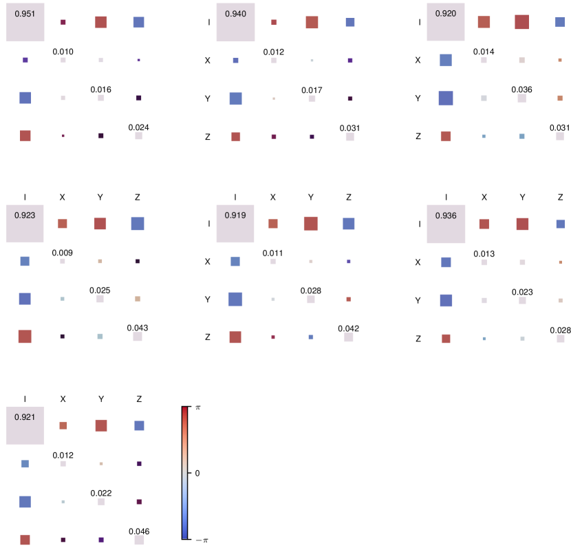
The duration of the mid-circuit detection procedure is dominated by the sideband cooling step with a duration on the order of the coherence time. Therefore, a dynamical decoupling sequence Carr and Purcell (1954); Meiboom and Gill (1958) is performed on the data qubits during the recooling procedure. This decoupling is implemented with a resonant radio frequency antenna driving the transition between the two ground states on the entire register simultaneously, where the data qubits are encoded during sideband cooling (red symbols). A refocusing pulse is applied approximately every millisecond in between cooling pulses for different motional modes. Figure 2C shows the process matrix Nielsen and Chuang (2010) of the evolution of data qubits during a full mid-circuit measurement procedure including dynamical decoupling averaged over all data qubits.
IV Steane QEC for the repetition code and the seven-qubit color code
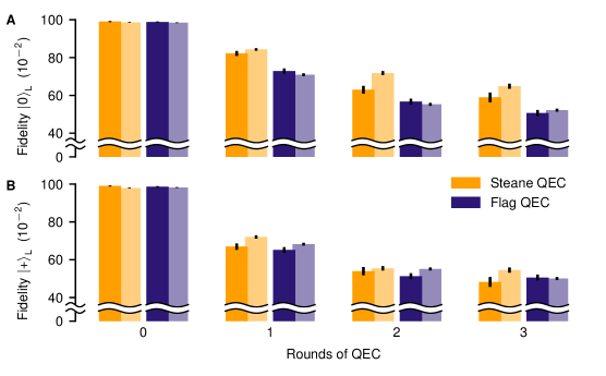
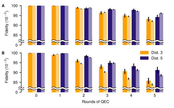
In this section we show the application of Steane QEC to 1D repetition codes and the 2D seven-qubit color code. First, we study the scaling of Steane QEC with code distance, by presenting results for distances and for both the bit- and phase-flip repetition code. The structure of the codes and the stabilizer generators are illustrated in Fig. 1B. Despite their simplicity, these codes share key properties, such as syndrome extraction, logical processing, and error suppression with fully-fledged topological QEC codes. Consequently, they routinely form a testbed for the latter Kelly et al. (2015); Google Quantum AI (2021). One round of error correction in repetition codes consists of only one half of the cycle illustrated in Fig. 1A since the codes can only correct either - or -errors. For example for Steane-type QEC on the distance- bit-flip code, a logical state is encoded in . The auxiliary logical qubit is prepared in a three-qubit GHZ state . If, for example, an -fault occurs on the first qubit, this will propagate onto the auxiliary logical qubit when the auxiliary qubit is coupled to the logical data qubit with a transversal CNOT gate. A final projective measurement of the auxiliary logical qubit in the -basis projects the state onto either or . We can extract the stabilizer values and , as given in Appendix A.2, by checking the parity of this measurement outcome. It is then possible to identify the initial fault on the first qubit based on the syndrome . For the distance- repetition code, the auxiliary logical state has to be verified to ensure that no single fault has caused a weight- error configuration on the auxiliary GHZ state. We do this by coupling a single flag qubit to the prepared auxiliary qubit, heralding weight- error configurations, as shown in Fig. A6 in Appendix A.2. No verification is required for , since any single fault only results in a correctable error configuration on each encoded block. The phase-flip code can be treated completely analogously to the bit-flip code. Figure 3 shows the probability to recover the target logical state, within the correction capabilities of the respective QEC code, for the bit- and phase-flip code with distances . We refer to this probability as logical fidelity (see Appendix E). Corrections suggested by the repeated syndrome extraction are accounted for via a Pauli frame update Knill (2005). We can identify that increasing the code distance from to improves logical fidelities for both the bit- and the phase-flip code. Lower fidelities for the phase-flip code compared to the bit-flip code can be attributed to dephasing on idling qubits. Experimental results are accompanied by Monte-Carlo simulations using an experimentally informed effective noise model. The model accounts for errors on single-qubit gates, two-qubit gates, qubit initialization, and measurements with error rates , , and , respectively. Furthermore, during mid-circuit measurements the remaining qubits experience noise which we model as asymmetric depolarizing noise with error probabilities , , , acting on all idling data qubits independently. These error probabilities are extracted from the experimental process matrix, quantifying the effect of mid-circuit measurements on idling (data) qubits, shown in Fig. 2C. A more detailed description of the error model can be found in Appendix B. The simulation data obtained with this relatively simple multi-parameter, incoherent noise model shows good agreement with the experimental data, which indicates that it captures the experiment well for the given error rates.
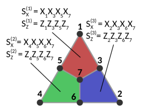
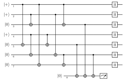
Going a step further, we now apply the above-described Steane-type QEC to the seven-qubit color code Steane (1996); Bombin and Martin-Delgado (2006); Nigg et al. (2014), shown in Fig. 1C, and compare its performance to the previously used flag-based QEC scheme Reichardt (2020); Ryan-Anderson et al. (2021); Postler et al. (2022). In the latter, the syndrome information is extracted by measuring stabilizers using additional auxiliary physical qubits, as illustrated in Fig. 1D. The seven-qubit color code is the smallest topological color code and encodes a single logical qubit while allowing the correction of a single arbitrary Pauli error. It has the highly desirable property of admitting a transversal and thus FT implementation of the entire Clifford group. Physical qubits are placed on the vertices of a two-dimensional graph and the encoded logical qubit is defined as the simultaneous -eigenstate of the six indicated stabilizer generators. A single flag qubit is used to verify the prepared logical state such that unsuccessful preparations can be discarded Goto (2016); Postler et al. (2022) analogous to usage in the distance- repetition code. The encoding circuit and lookup table are given in Appendix A.1.
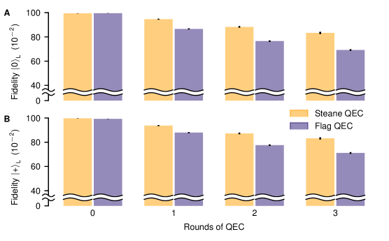
Figure 4 shows the logical fidelities we obtained experimentally and numerically from Monte-Carlo simulations. We find an advantageous performance in terms of fidelity for Steane-type QEC compared to the flag-based QEC scheme, where the performance benefit of Steane QEC is more pronounced for the state . The reason for this asymmetry is that the dominating error source in the experimental setup at hand is asymmetric depolarizing noise on the data qubits during mid-circuit measurements. Additionally dephasing of data qubits is taking place during the implementation of gates on the auxiliary qubits (see Tab. 3 in Appendix B). This conflates the logical failure rates for the different protocols and partially veils the advantage of Steane QEC, which is most pronounced in the regime of dominating two-qubit error rates. Therefore, we estimate the projected advantage of Steane-type QEC by numerically simulating logical error rates in a setting where the only noise source are two-qubit gate errors. In this regime, we find that the logical error rate of Steane-type QEC is suppressed by as much as a factor of 2, compared to flag-type QEC (see Fig. A5 in Appendix A.1). Experimental improvements like an extended coherence time on the order of seconds Harty et al. (2014); Ruster et al. (2016); Wang et al. (2021) or composite pulses robust against laser amplitude noise and crosstalk Wimperis (1989, 1994) could further mitigate perturbations of idling data qubits during mid-circuit measurements and therefore extend the advantage in logical fidelity offered by the Steane-type over flag-type QEC also in the present experimental setup. Additional results on the extraction of only the () syndrome for the logical state () are presented in Appendix F.
V Conclusions and Outlook
In this work we show practical advantage of Steane over flag-based QEC in a noisy intermediate-scale trapped-ion quantum processor. We have implemented up to five rounds of Steane QEC for bit-flip and phase-flip repetition codes with distances and , and observe an improvement of the logical fidelity with larger distances. This increase in spite of larger qubit and gate overhead per logical qubit shows that both codes were operated below their respective thresholds. We further demonstrated an advantage of repeated Steane QEC on the seven-qubit color code, where multiple complete rounds of error correction including repeated mid-circuit measurements present substantial experimental challenges. Numerical simulations based on a multi-parameter depolarizing error model, informed by experimentally estimated error rates of basic quantum operations, underpin this finding and capture the features in the experimental data. The improved QEC performance has been achieved without the necessity to make any changes to the hardware, but is rooted in the carefully crafted quantum circuit design underlying the Steane-type QEC approach. The present implementation is currently limited by errors during mid-circuit measurements. Therefore, the benefit of Steane QEC will increase up to the numerically anticipated margin of about a factor of 2, if the error rate of the mid-circuit measurement procedure becomes smaller than the entangling gate errors.
The results presented in this work establish Steane QEC as a new paradigm in experimental QEC by showing reduced error rates of encoded qubits compared to other QEC protocols. The demonstrated Steane-type QEC approach is especially relevant in the context of the emergence of larger qubit registers with efficient implementations of entangling logical gates on various platforms. The possibility of applying transversal CNOT gates in parallel in this paradigm enables the extraction of -type and -type error syndromes each within one circuit time step. We believe Steane QEC will play a pivotal role towards large-scale fault-tolerant quantum computation owing to its increased logical fidelities, and modularity allowing to harness the emerging capabilities of efficiently and fault-tolerantly coupled logical qubits as building blocks.
Acknowledgments
Please also note the preprint entitled ‘Comparing Shor and Steane Error Correction Using the Bacon-Shor Code’ by S. Huang, K. R. Brown, and M. Cetina on related work.
Funding:
We gratefully acknowledge support by the European Union’s Horizon Europe research and innovation program under Grant Agreement Number 101114305 (“MILLENION-SGA1” EU Project), the US Army Research Office through Grant Number W911NF-21-1-0007, the European Union’s Horizon Europe research and innovation program under Grant Agreement Number 101046968 (BRISQ), the ERC Starting Grant QCosmo under Grant Number 948893, the ERC Starting Grant QNets through Grant Number 804247, the Austrian Science Fund under Project Number F7109 (SFB BeyondC), the Austrian Research Promotion Agency under Contracts Number 896213 (ITAQC), the Office of the Director of National Intelligence (ODNI), Intelligence Advanced Research Projects Activity (IARPA), via the U.S. Army Research Office through Grant Number W911NF-16-1-0070 under the LogiQ program, and by IARPA and the Army Research Office, under the Entangled Logical Qubits program through Cooperative Agreement Number W911NF-23-2-0216. This research is also part of the Munich Quantum Valley (K-8), which is supported by the Bavarian state government with funds from the Hightech Agenda Bayern Plus. We further receive support from the IQI GmbH, and by the German ministry of science and education (BMBF) via the VDI within the project IQuAn, and by the Deutsche Forschungsgemeinschaft (DFG, German Research Foundation) under Germany’s Excellence Strategy ‘Cluster of Excellence Matter and Light for Quantum Computing (ML4Q) EXC 2004/1’ 390534769.
The views and conclusions contained in this document are those of the authors and should not be interpreted as representing the official policies, either expressed or implied, of IARPA, the Army Research Office, or the U.S. Government. The U.S. Government is authorized to reproduce and distribute reprints for Government purposes notwithstanding any copyright notation herein.
Authors contribution:
L.P. and I.P. carried out the experiments. L.P., I.P., C.D.M., P.S. and T.M. contributed to the experimental setup. L.P., F.B. and M.R. analyzed the data. F.B., S.H. and M.R. performed the numerical simulations. F.B., S.H. and M.R. performed circuit analysis, characterization and theory modeling. L.P., F.B., I.P., C.D.M., S.H., P.S. and M.R. wrote the manuscript, with contributions from all authors. R.B., P.S., M.R., M.M. and T.M. supervised the project.
Competing interests:
R.B. and T.M. are connected to Alpine Quantum Technologies GmbH, a commercially oriented quantum computing company.
Data and materials availability:
The data underlying the findings of this work are available at https://doi.org/10.5281/zenodo.10390470. All codes used for data analysis are available from the corresponding author upon reasonable request.
References
- Google Quantum AI (2021) Google Quantum AI, Exponential suppression of bit or phase errors with cyclic error correction, Nature 595, 383 (2021).
- Krinner et al. (2022) S. Krinner, et al., Realizing repeated quantum error correction in a distance-three surface code, Nature 605, 669 (2022).
- Zhao et al. (2022) Y. Zhao, et al., Realization of an Error-Correcting Surface Code with Superconducting Qubits, Phys. Rev. Lett. 129, 030501 (2022).
- Google Quantum AI (2023) Google Quantum AI, Suppressing quantum errors by scaling a surface code logical qubit, Nature 614, 676 (2023).
- Gupta et al. (2023) R. S. Gupta, et al., Encoding a magic state with beyond break-even fidelity, arXiv eprint 2305.13581 (2023).
- Hilder et al. (2022) J. Hilder, et al., Fault-Tolerant Parity Readout on a Shuttling-Based Trapped-Ion Quantum Computer, Phys. Rev. X 12, 011032 (2022).
- Egan et al. (2021) L. Egan, et al., Fault-tolerant control of an error-corrected qubit, Nature 598, 281 (2021).
- Ryan-Anderson et al. (2021) C. Ryan-Anderson, et al., Realization of real-time fault-tolerant quantum error correction, Phys. Rev. X 11, 041058 (2021).
- Postler et al. (2022) L. Postler, et al., Demonstration of fault-tolerant universal quantum gate operations, Nature 605, 675 (2022).
- Ryan-Anderson et al. (2022) C. Ryan-Anderson, et al., Implementing Fault-tolerant Entangling Gates on the Five-qubit Code and the Color Code, arXiv eprint 2208.01863 (2022).
- Menendez et al. (2023) D. H. Menendez, A. Ray, and M. Vasmer, Implementing fault-tolerant non-Clifford gates using the [[8,3,2]] color code, arXiv eprint 2309.08663 (2023).
- Wang et al. (2023) Y. Wang, et al., Fault-Tolerant One-Bit Addition with the Smallest Interesting Colour Code, arXiv eprint 2309.09893 (2023).
- Pokharel and Lidar (2022) B. Pokharel and D. Lidar, Better-than-classical Grover search via quantum error detection and suppression, arXiv eprint 2211.04543 (2022).
- Bluvstein et al. (2023) D. Bluvstein, et al., Logical quantum processor based on reconfigurable atom arrays, arXiv eprint 2312.03982 (2023).
- Steane (1997) A. M. Steane, Active Stabilization, Quantum Computation, and Quantum State Synthesis, Phys. Rev. Lett. 78, 2252 (1997).
- Shor (1996) P. W. Shor, Fault-tolerant quantum computation, in Proceedings of 37th Conference on Foundations of Computer Science (IEEE, 1996).
- Chamberland and Beverland (2018) C. Chamberland and M. E. Beverland, Flag fault-tolerant error correction with arbitrary distance codes, Quantum 2, 53 (2018).
- Reichardt (2020) B. W. Reichardt, Fault-tolerant quantum error correction for Steane’s seven-qubit color code with few or no extra qubits, Quantum Sci. Technol. 6, 015007 (2020).
- Nielsen and Chuang (2010) M. A. Nielsen and I. L. Chuang, Quantum computation and quantum information (Cambridge university press, 2010).
- Negnevitsky et al. (2018) V. Negnevitsky, et al., Repeated multi-qubit readout and feedback with a mixed-species trapped-ion register, Nature 563, 527 (2018).
- Pino et al. (2021) J. M. Pino, et al., Demonstration of the trapped-ion quantum CCD computer architecture, Nature 592, 209 (2021).
- Erickson et al. (2022) S. D. Erickson, et al., High-Fidelity Indirect Readout of Trapped-Ion Hyperfine Qubits, Phys. Rev. Lett. 128, 160503 (2022).
- Zhu et al. (2023) D. Zhu, et al., Interactive cryptographic proofs of quantumness using mid-circuit measurements, Nat. Phys. 19, 1725 (2023).
- Riebe et al. (2008) M. Riebe, et al., Deterministic entanglement swapping with an ion-trap quantum computer, Nat. Phys. 4, 839 (2008).
- Monz et al. (2016) T. Monz, et al., Realization of a scalable Shor algorithm, Science 351, 1068 (2016).
- Manovitz et al. (2022) T. Manovitz, Y. Shapira, L. Gazit, N. Akerman, and R. Ozeri, Trapped-Ion Quantum Computer with Robust Entangling Gates and Quantum Coherent Feedback, PRX Quantum 3, 010347 (2022).
- Schindler et al. (2013) P. Schindler, et al., A quantum information processor with trapped ions, New J. Phys. 15, 123012 (2013).
- Carr and Purcell (1954) H. Y. Carr and E. M. Purcell, Effects of Diffusion on Free Precession in Nuclear Magnetic Resonance Experiments, Phys. Rev. 94, 630 (1954).
- Meiboom and Gill (1958) S. Meiboom and D. Gill, Modified spin-echo method for measuring nuclear relaxation times, Rev. Sci. Instrum. 29, 688 (1958).
- Kelly et al. (2015) J. Kelly, et al., State preservation by repetitive error detection in a superconducting quantum circuit, Nature 519, 66 (2015).
- Knill (2005) E. Knill, Quantum computing with realistically noisy devices, Nature 434, 39 (2005).
- Steane (1996) A. Steane, Multiple-particle interference and quantum error correction, Proc. Phys. Soc. A 452, 2551 (1996).
- Bombin and Martin-Delgado (2006) H. Bombin and M. A. Martin-Delgado, Topological quantum distillation, Phys. Rev. Lett. 97, 180501 (2006).
- Nigg et al. (2014) D. Nigg, et al., Quantum computations on a topologically encoded qubit, Science 345, 302 (2014).
- Goto (2016) H. Goto, Minimizing resource overheads for fault-tolerant preparation of encoded states of the Steane code, Sci. Rep. 6, 19578 (2016).
- Harty et al. (2014) T. P. Harty, et al., High-Fidelity Preparation, Gates, Memory, and Readout of a Trapped-Ion Quantum Bit, Phys. Rev. Lett. 113, 220501 (2014).
- Ruster et al. (2016) T. Ruster, et al., A long-lived Zeeman trapped-ion qubit, Appl. Phys. B 122, 254 (2016).
- Wang et al. (2021) P. Wang, et al., Single ion qubit with estimated coherence time exceeding one hour, Nat. Commun. 12, 233 (2021).
- Wimperis (1989) S. Wimperis, Composite pulses with rectangular excitation and inversion profiles, J. Magn. Reson. 83, 509 (1989).
- Wimperis (1994) S. Wimperis, Broadband, Narrowband, and Passband Composite Pulses for Use in Advanced NMR Experiments, J. Magn. Reson. 109, 221 (1994).
- Aliferis et al. (2006) P. Aliferis, D. Gottesman, and J. Preskill, Quantum Accuracy Threshold for Concatenated Distance-3 Codes, Quantum Inf. Comput. 6, 97–165 (2006).
- Chamberland (2018) C. Chamberland, New methods in quantum error correction and fault-tolerant quantum computing, Ph.D. thesis, University of Waterloo (2018).
- Gidney (2021) C. Gidney, Stim: a fast stabilizer circuit simulator, Quantum 5, 497 (2021).
- Ryan-Anderson (2018) C. Ryan-Anderson, Quantum algorithms, architecture, and error correction, Ph.D. thesis, The University of New Mexico (2018).
- Pogorelov et al. (2021) I. Pogorelov, et al., Compact Ion-Trap Quantum Computing Demonstrator, PRX Quantum 2, 020343 (2021).
- McKay et al. (2017) D. C. McKay, C. J. Wood, S. Sheldon, J. M. Chow, and J. M. Gambetta, Efficient Z gates for quantum computing, Phys. Rev. A 96, 022330 (2017).
- Sørensen and Mølmer (2000) A. Sørensen and K. Mølmer, Entanglement and quantum computation with ions in thermal motion, Phys. Rev. A 62, 022311 (2000).
- Maslov (2017) D. Maslov, Basic circuit compilation techniques for an ion-trap quantum machine, New J. Phys. 19, 023035 (2017).
- Wilson (1927) E. B. Wilson, Probable inference, the law of succession, and statistical inference, J. Am. Stat. Assoc. 22, 209 (1927).
Appendix A Quantum error correcting codes
A.1 The seven-qubit color code
The seven-qubit color code is constructed by placing physical qubits on the vertices of a graph Steane (1996). The encoded logical qubit is defined as the simultaneous -eigenstate of the six stabilizer generators
| (2) | |||
as illustrated in Fig. 1A and Fig. A1. The logical operators are given by and , which can be expressed as weight- operators by multiplication with stabilizers. For instance, multiplying with gives the weight- logical operator . The circuit shown in Fig. A2 is used to encode a logical state in the seven-qubit color code Goto (2016).
In the error-free case, a measurement of the set of stabilizer generators will yield the outcome for each one, since a valid code state is a -eigenstate of these operators. If a single Pauli fault occurs, this will anticommute with a set of stabilizers. The measurement outcomes in this case will yield the outcome for a set of stabilizers. This syndrome measurement outcome is unique to the initial single Pauli fault when excluding error configurations of weight greater than one. Therefore, one can correct for this error and recover the code state. However, higher-weight error configurations break this uniqueness and can lead to logical errors when applying the recovery operation. For instance, the weight- error configuration and the weight- configuration lead to the same syndrome . Applying the recovery operation would lead to a logical error for the weight- error case, as the weight- configuration is up to multiplication with a stabilizer generator equivalent to . Table 1 summarizes the possible -syndrome measurement outcomes and the corresponding recovery operation, which corrects any single Pauli -error. Since the seven-qubit color code is self-dual, i.e. symmetric under exchange of and stabilizers, the lookup table for Pauli -corrections based on the measured -syndrome is the same.
The syndrome can be extracted using Steane-type QEC with the circuit shown in Fig. A3, where transversal CNOT gates copy errors onto an auxiliary logical qubit which is then measured projectively. Figure A4 shows the circuit we use for flagged syndrome readout on the seven-qubit color code Ryan-Anderson et al. (2021); Postler et al. (2022); Reichardt (2020). If no error is detected in a first round of flagged stabilizer measurements, we assume that no error has occurred and proceed. If a non-trivial syndrome is measured, the complete syndrome is measured again with unflagged circuits to distinguish the dangerous propagated flag errors from non-flag errors. If the two syndromes agree, we take this as a final syndrome for error correction with lookup table Tab. 1. If they do not agree and the unflagged syndrome coincides with a flag-error syndrome in Tab. 2, we apply the corresponding flag-error correction. In case the unflagged syndrome is not in the flag-lookup table, the single-qubit recovery from Tab. 1 is used. Note that while one could immediately apply the correction to the data register, it is admissible to just keep track of this in software (known as Pauli frame tracking) as long as no logical non-Clifford gate is applied. The experimental setup currently does not allow for real-time changes of the gate sequence based on outcomes of mid-circuit measurements. For the realization of flagged QEC we experimentally implement both possible circuits, with and without a second unflagged measurement of the stabilizer generators, and all combinations thereof for multiple QEC cycles. In post-selection we discard all implementations where the flagged syndrome was trivial, but an unflagged readout was following, and vice-versa.
| Recovery | |
| Recovery | |
|---|---|
We numerically calculate the fidelities for the limiting case where all error rates except are set to , as shown in Fig. A5, in order to estimate the potential advantage of Steane-type QEC over the flag-based approach. Since there is no additional dephasing included, the systematic difference in fidelity between the two logical states and vanishes. The fidelities for the Steane-type approach are higher than for the flag-based protocol and this difference increases with the number of QEC rounds. After two rounds of QEC, the fidelity for the Steane-type approach is already more than higher than for the flag-based protocol. This promises an advantage of Steane-type QEC in the regime of dominating two-qubit error rates.
A.2 The 1D repetition code
For the -qubit bit-flip code Nielsen and Chuang (2010), the logical is encoded in copies of as . The stabilizer generators are given by pairs of neighboring Pauli- operators {} and the logical operators are and . Analogously, the phase-flip code takes repetitions of to encode information redundantly on multiple qubits. In this case, one can define the -qubit state and the stabilizers correspond to pairs of Pauli--operators {} and the logical operators are given by and . Steane-type QEC is performed by initializing a second logical qubit in the corresponding logical and applying a transversal CNOT gate, as shown exemplarily in Fig. A6 for the distance- repetition code.

Appendix B Effective noise model and simulation methods
In order to estimate the logical fidelities of the discussed error correction protocols, we perform Monte-Carlo simulations using STIM Gidney (2021) and PECOS Ryan-Anderson (2018). Every component in a circuit is modeled as an ideal operation followed by an error drawn from an error set with a given probability . We consider depolarizing noise channels on single- and two-qubit gates
| (3) | ||||
with the error sets
| (4) | ||||
where are the single-qubit Pauli operators with . For the single qubit case we give the more general channel to capture the asymmetric case found for the errors induced during mid-circuit measurements. The general formula reduces to the symmetric depolarizing case by choosing all three Pauli errors with equal probability , as we do for the single-qubit gate error. The parameters and specify the probability that any one of the errors of the corresponding error set occurs on the qubits which are acted upon. Qubits are initialized and measured in the computational basis. Faults on these operations are modeled by applying -errors after state preparations and before measurements with a probability and , respectively. Furthermore, we include noise on idling qubits, which are not acted upon with a gate at a given step of the protocol. Since the dominating noise on idling qubits is dephasing due to magnetic field fluctuations, which limits the decoherence time ms, we model the noise channel for idling qubits by Pauli- faults as
| (5) |
The probability of a -fault on each idling qubit depends on the execution time of the performed gate and is given by
| (6) |
Mid-circuit detections are performed in order to perform multiple rounds of error correction, where auxiliary qubits are measured while keeping the data qubits intact. The idling data qubits experience noise during this mid-circuit detection, which we model as an asymmetric depolarizing channel on all data qubits. We estimate the individual Pauli error rates in this channel based on single-qubit process tomography. All error rates and gate times are summarized in Tab. 3.
| Operation | Error rate | Duration |
|---|---|---|
| Two-qubit gate | ||
| Single-qubit gate | ||
| Measurement | ||
| Preparation | ||
| Mid-circuit detection | ||
Appendix C Experimental methods
All experiments presented in this manuscript are conducted on a trapped-ion quantum processor Pogorelov et al. (2021). In a non-segmented macroscopic Paul trap a string of sixteen 40Ca+ ions is trapped with inter-ion spacing ranging from to , set by trap parameters. The center-of-mass modes of the ion string in the pseudo-harmonic potential of the trap have oscillation frequencies of and , for the direction along the ion string (referred to as axial) and the two perpendicular directions (referred to as radial), respectively. The first step of every experimental cycle is a Doppler cooling pulse acting on the transition at a wavelength of (see Fig. A7) with a duration of . Simultaneously the ion chain is illuminated with light at to avoid pumping to the dark state by driving any population trapped there back to the state . Both laser beams act on all ions simultaneously and have spatial overlap with all motional modes. The two lowest-frequency axial modes and all radial modes are further cooled close to the ground state by resolved sideband cooling Schindler et al. (2013). The ions are illuminated by a laser beam red-detuned by the respective motional frequency from the transition at . For the axial modes the laser propagates along the ion string, whereas the radial modes are cooled by a steerable, addressed beam illuminating only one ion at a time from a direction perpendicular to the ion string. To cool the radial modes the ion having the strongest coupling to the respective motional mode is illuminated. All modes within approximately from the laser frequency are cooled, which allows us to cool 34 modes with only 15 frequency settings. To accelerate the cooling process ions excited to the state are pumped to the state using laser light at from where they rapidly decay to one of the ground states. This sideband cooling cycle is repeated up to five times depending on the mode, where one cycle takes . The finalizing step of the state preparation procedure is to prepare all ions in by exciting the transition with axial light while speeding up the decay to the ground state using light, as for sideband cooling.
The coherent manipulation of the individual qubits in the register subsequent to state preparation is exclusively done via tightly focused laser pulses with a propagation direction perpendicular to the ion string addressing the qubit transition . The experimental setup allows us to illuminate up to two ions simultaneously. Addressing a single ion with light resonant to the qubit transition allows us to implement operations of the form , where are single-qubit Pauli matrices. The rotation axis can be controlled via the light phase, the rotation angle via light intensity and pulse duration. The duration of a pulse with is . Together with virtual Z rotations McKay et al. (2017) this operation allows us to implement arbitrary single-qubit unitary operations. The gate set is completed by adding the entangling Mølmer-Sørensen interaction, where any two ions may be illuminated with bichromatic light slightly detuned from the motional sidebands corresponding to the radial mode at frequency Sørensen and Mølmer (2000). Adjusting the gate time to , where is the detuning from the motional sidebands, implements the gate , which is equivalent to the CNOT gate up to single-qubit rotations Maslov (2017). Qubit state readout after application of a gate sequence to the qubit register is implemented by simultaneously illuminating the whole register with laser light at wavelengths of and . While qubits projected to the computational state repeatedly emit photons at a wavelength of after being excited to and returning to , qubits projected to are not affected by those light fields and do not emit photons Schindler et al. (2013). Imaging the ion string on an electron multiplying charge-coupled device (EMCCD) camera allows for the spatially resolved detection of light emission from the ion string, and therefore the computational basis bit string the qubit register was projected into can be reconstructed.
Error rates for single-qubit gates are estimated from single-qubit randomized benchmarking on the 16-qubit register. We find an error rate per gate averaged over all 16 qubits of with a standard deviation of . The two-qubit error rate is estimated by preparing a 16-qubit GHZ state and comparing the experimentally measured fidelity to simulated fidelities from numerical simulations accounting for errors on single-qubit gates, two-qubit gates, initialization and measurements. Averaging over multiple instances of the prepared GHZ state over the course of around 13 hours gives a mean fidelity of with a standard deviation of , corresponding to an estimated two-qubit error rate with a standard deviation of . Typical values for qubit initialization and measurement fault rates are in the device under consideration Schindler et al. (2013).
C.1 Mid-circuit measurements
For mid-circuit measurements only a part of the register, referred to as auxiliary qubits, is supposed to be projected into the computational basis, while a part of the register, referred to as data qubits, is ideally unaffected. To avoid projecting the data qubits, their qubit encoding is transferred to and by applying addressed pulses with (-pulses) on the transition for all data qubits. Subsequently the same detection pulse as for the final detection is applied. Recoil of scattered photons from bright auxiliary qubits heat up the ion string, which would lead to reduced gate fidelities after the mid-circuit measurement. Therefore a Doppler cooling pulse is applied. To recool the ion string close to the motional ground state an additional sideband cooling step is necessary. The data qubit encoding is transferred to and by applying -pulses on the transitions associated to the states and as sideband cooling involves illuminating the ion string with light, which would otherwise destroy any information encoded in the manifold. Then the same sideband cooling pulse scheme as for state preparation is applied, apart from the fact that axial modes are not cooled and ions encoding data qubits are excluded from the set of allowed cooling ions. Cooling axial modes would require using the axial beam, as the addressed beam does not have overlap with the direction of motion of axial modes, and therefore would also affect data qubits. Prior to every sideband cooling pulse the respective ion is pumped to by applying two repetitions of a -pulse on the transition followed by a pulse of light. The mid-circuit measurement is finalized by repeating the pumping cycle for all auxiliary qubits that are supposed to be reused four times, and restoring the encoding of the data qubits by applying a -pulse on the transition . The mid-circuit sideband cooling procedure requires around .
C.2 Dynamical decoupling
The coherence time in the optical-qubit encoding and the ground-state encoding is on the order of and , respectively. Idling data qubits would thus suffer from significant dephasing during sideband cooling if no countermeasures were taken. Therefore a dynamical decoupling sequence is performed on the data qubits during the recooling procedure to preserve coherence. This decoupling is implemented with a RF antenna radiating at acting on the entire register simultaneously which drives the transition between the two ground states, where the data qubits are encoded during sideband cooling. The antenna with a diameter of about is connected to resonant circuit and is mounted outside the vacuum chamber as close as possible to the ion string. Driving the resonant antenna with a power of approximately allows us to implement a bit-flip in . A decoupling pulse is applied approximately every millisecond in between cooling pulses for different motional modes. Under the application of this decoupling scheme we do not see any significant dephasing up to a waiting time of , which indicates an effective coherence time larger than . The effect of a full mid-circuit measurement on data qubits is characterized via single-qubit process tomography of the data qubits using linear reconstruction. Figure 2C shows the chi matrix representation Nielsen and Chuang (2010) of the process averaged over all data qubits in the Pauli basis, whereas Fig. A8 shows the underlying process matrices for the individual data qubits. The average fidelity is with a standard deviation of . The averaged process matrix data is also used to inform the error model described in Appendix B, as there are no salient differences between the individual matrices. These error probabilities are extracted from the experimental process matrix, quantifying the effect of mid-circuit measurements on data qubits, shown in Fig. 2C.
Appendix D Uncertainty estimation
The uncertainties given in this work account for statistical errors under the assumption of an underlying binomial distribution of the measurement outcomes. We make use of the Wilson score interval Wilson (1927) in order to get error intervals in the interval even for probabilities close to or . The upper (referred to as ’’ in the formula) and lower (’’) bound of the interval for a probability measured with shots are given by
| (7) |
where with being the quantile function of the normal distribution and being the target error rate. We choose which corresponds to a confidence level of .
Appendix E Logical fidelity
The figure of merit for the quality of a logical state we choose in this work is the logical fidelity, which is the probability of retrieving the correct logical state. A single logical qubit state is given by
| (8) |
where , and are the logical operators and are single-qubit Pauli matrices. Then the logical fidelity of with respect to a logical target state after performing an ideal round of QEC is given by
| (9) |
with being the projector on the logical target state. For the logical Pauli states and the projectors read
| (10) |
leading to the expressions
| (11) |
for the logical fidelities of the logical states considered in this work.
Appendix F Additional results
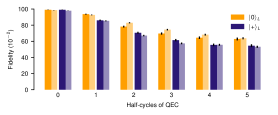
In addition to the implementation of multiple rounds of Steane QEC on the seven-qubit color code we realize repetitive readout of a single type of stabilizer generators, corresponding to executing either the first or the second half of the scheme displayed in Fig. 1C. The syndrome extraction is applied to a logical Pauli state sensitive to the corrections suggested by the syndrome measurement, e.g. -type stabilizer generators are measured for the input state and -type stabilizer generators are measured for the input state . We refer to one readout as a half-cycle of QEC. We implement up to five half-cycles of QEC with the corresponding logical fidelities being shown in Fig. A9. Again we see good agreement of experiments with data from numerical simulations.