Analysis of lattice locations of deuterium in tungsten and its application for predicting deuterium trapping conditions
Abstract
Retention of hydrogen isotopes (protium, deuterium and tritium) in tungsten is one of the most severe issues in design of fusion power plants, since significant trapping of tritium may cause exceeding radioactivity safety limits in future reactors. Hydrogen isotopes in tungsten can be detected using the nuclear reaction analysis method in channeling mode (NRA/C). However, the information hidden within the experimental spectra is subject to interpretation. In this work, we propose the methodology to interpret the response of the experimental NRA/C spectra to the specific lattice locations of deuterium by simulations of the NRA/C spectra from atomic structures of deuterium lattice locations as obtained from the first principles calculations. We show that trapping conditions, i.e., states of local crystal structures retaining deuterium, affect the lattice locations of deuterium and the change of lattice locations can be detected by ion channeling method. By analyzing the experimental data, we are able to determine specific information on the deuterium trapping conditions, including the number of deuterium atoms trapped by one vacancy as well as the presence of impurity atoms along with deuterium in vacancies.
1 Introduction
The interaction of hydrogen isotopes (protium, deuterium and tritium) with metals has garnered sustained interest due to application of hydrogen in energy storage [1] as well as its adverse effects on the properties of structural materials [2, 3]. Among various metals, the interaction of hydrogen isotopes with tungsten has received particular attention, in particular because tungsten is a promising candidate for the plasma facing wall of fusion reactors [4], where it needs to withstand extremely high fluxes of hydrogen isotopes [5, 6]. A comprehensive understanding of the behavior of hydrogen isotopes in tungsten, including its lattice locations and trapping conditions, is essential for the development of future fusion devices.
Since hydrogen is the lightest element, identifying its geometrical configuration in the crystal structure of materials is not a straightforward process. For example, direct imaging of hydrogen in metal hydride is a demanding task due to the weight difference between hydrogen and heavy elements [7]. The low mass of hydrogen renders it essentially invisible to ion beam analysis methods that rely on backscattering techniques. On the other hand, the low atomic number of hydrogen opens the gateway for methods that take advantage of its weak Coulomb barrier, i.e., nuclear reaction analysis (NRA) [8]. NRA has been used to study hydrogen in metals over decades [9, 10, 11, 12, 13, 14]. By using a D(3He,p)4He reaction, it can perform a depth profiling of deuterium in tungsten up to several micrometers, with a depth resolution on the order of magnitude of submicrometer [15].
Notably, NRA in channeling mode (NRA/C) is a unique method to determine the lattice locations of deuterium in tungsten [16]. In this mode, probing ions are confined in open channels between rows of target atoms so that NRA/C signals would depend on the location of impurity atoms to be studied. By applying NRA/C, Picraux and Vook [17, 18] investigated the lattice locations of 15 - 30 keV deuterium implanted into tungsten at room temperature with a relatively low fluence ( cm-2). They performed angular scans through <100> axis of tungsten, and concluded that the deuterium atoms were located at a position at or close to tetrahedral interstitial sites (TIS). Ligeon el al. [19] explored the location of deuterium in a large group of metals. For the case of tungsten, they implanted 10 - 15 keV deuterium and suggested that the occupation site of deuterium was slightly displaced from the TIS in a temperature range of 15 K to room temperature. Nagata et al. [20] carried out similar NRA/C experiments using 1 keV deuterium, and reported similar results.
In principle, the lattice locations of deuterium should be affected by the trapping conditions. This trapping condition defines by which kind of crystal structures the hydrogen atoms are trapped, for example, monovacancy or vacancy clusters. It also describes the actual state of the trapping structures, for example, how many hydrogen atoms are in a monovacancy and if there are impurity atoms in the monovacancy. The trapping conditions of hydrogen in tungsten have been extensively studied by first principles calculations based on density functional theory (DFT). Note that the trapping conditions of different hydrogen isotopes should be similar, as the isotope mass does not affect chemical bonding, and hence DFT calculations or experiments for protium are directly applicable to deuterium, and vice versa. Several independently performed DFT calculations have shown that hydrogen prefers to occupy the tetrahedral interstitial site in a perfect tungsten [21, 22, 23]. However, the solubility of hydrogen in tungsten is very low [24] so that the hydrogen retained in tungsten at room temperature is mainly trapped by crystal defects [4]. Moreover, experiments of hydrogen and deuterium diffusion have shown that single hydrogen or deuterium atoms migrate very rapidly in tungsten even at cryogenic temperatures via a quantum-mechanical migration mechanism [4, 25, 26, 27]. Hence it is implausible that any appreciable concentration of isolated hydrogen or deuterium atoms would be present in pristine tungsten in experiments. Instead, The trapping of hydrogen by vacancy-type defects, such as, vacancy and vacancy clusters, is of particular interest due to high binding energies (> 1 eV) [28, 29]. Furthermore, the open volume of vacancy-type defects is able to accommodate multiple hydrogen atoms [30]. Interstitial-type defects can also attract hydrogen, but the corresponding binding energies tend to be weak [31, 32].
The insights gained from DFT calculations have frequently been used to interpret trapping conditions of deuterium in experiments [33, 34, 35]. However, with regard to the lattice locations of deuterium, a connection between DFT calculations and NRA/C experiments has not been well established. In fact, results obtained from the two methods are even seemingly conflicting with each other. As an example, if we assume that primary trapping structures for the deuterium in the previously mentioned NRA/C experiments [17] are vacancies as postulated in literature [36], then we have a contradictory result: the NRA/C experiments indicate that deuterium atoms are located near the TIS; whereas DFT calculations indicate that the lattice locations of deuterium is near the octahedral interstitial site (OIS) [37, 38, 28, 39].
This apparent paradox indicates that deuterium trapping conditions possess a complex nature. The change of exact state of trapping conditions can affect the lattice locations of deuterium. This follows from the DFT calculations which show that the hydrogen atoms tend to shift from OIS to TIS position in a vacancy, when the filling level of hydrogen, i.e., the number of hydrogen atoms trapped by the vacancy, increases up to 12 [40]. Yet, the temperature effect imposes an additional complication: it is reported that at room temperature a vacancy can hold in only up to 6 hydrogen atoms [39, 41]. Hence, it is not clear whether the decoration of vacancies by no more than 6 deuterium atoms can be used to explain the NRA/C experimental results.
In this work, we investigated the lattice locations of deuterium in tungsten by combination of NRA/C methods and DFT calculations. DFT calculations were employed to determine the lattice locations of hydrogen (including its isotope deuterium) in various trapping conditions. In order to establish a robust connection between DFT calculations and NRA/C experiments, we developed an NRA/C simulation tool which uses the DFT results as an input and generates the NRA/C signals comparable to experimental ones. We present the response of the simulated NRA/C signals to deuterium trapped at different conditions and compare the simulated spectra to the experimental ones from Refs.[17, 18]. We demonstrate that the connection between the lattice locations and trapping conditions of deuterium can not only be used to resolve the inconsistency between the NRA/C experiments and DFT calculations, but also can provide valuable information regarding the filling level of deuterium in vacancies and evolution of trapping conditions.
2 Methodology
2.1 First principles calculations
First principles calculations based on the DFT approach were performed using the Vienna ab initio simulation package (VASP) [42, 43, 44] with the projector augmented wave potentials [45, 46]. The electron exchange correlation was described with generalized gradient approximation (GGA) using Perdew-Burke-Ernzerhof (PBE) functionals [47]. The configuration of valence electrons used for tungsten, hydrogen, helium, carbon and oxygen were , , , and , respectively. Since these DFT calculations seek the ground state configuration of atoms at 0 K, the results will be the same for any hydrogen isotope. We employed a supercell composed of 54 lattice points, and applied a -point grid obtained using the Monkhorst-Pack method [48]. The lattice parameter of the perfect tungsten determined by these DFT calculations is 3.172 Å. A plane wave energy cutoff of 350 eV was used for most of the calculations. When the supercell contained helium or oxygen, the energy cutoff was increased to 500 eV. Relaxation of atomic positions was performed, in which the energy and atomic force convergence criteria were set to eV and eV/Å, respectively. After the relaxation, the positions of hydrogen atoms were transferred to the NRA/C simulations.
The binding energy between two entities and , , is calculated as follows:
| (1) |
where and represent the energy of supercell containing and , respectively, represents the energy of supercell containing both and in interaction with each other, and represents the energy of the supercell without and . Since zero point energy (ZPE) is not negligible for light atoms, ZPE calculations were performed for hydrogen and helium atoms based on harmonic approximations, in which the positions of other atoms were kept fixed. The binding energy including the ZPE correction, , is calculated by:
| (2) |
where , and are the total ZPE of suppercell containing , and the complex, respectively.
The formation energy of the entity , , is calculated as follows:
| (3) |
where is the difference in the number of element between the supercell with and without , and represents the energy of element (for hydrogen, is taken as the half of the energy of a hydrogen molecule). Using a similar method to Eq.(2), the formation energy including ZPE correction, , is calculated by adding the corresponding ZPE to each term of Eq.(3).
2.2 Development of NRA/C simulation program
We developed a NRA/C simulation program based on a Monte Carlo code called RBSADEC that was originally developed to simulate Rutherford backscattering spectrometry in channeling mode (RBS/c) [49, 50, 51]. An incorporation of NRA/C and RBS/c in the same code is natural due to the intimate relation between the two techniques [52]. The simulation deals with nuclear reactions in the following form:
| (4) |
where is a probing ion, is a target atom that can have nuclear reaction with , is an emitting particle that is to be detected, is a residual nucleus, and represents an energy balance.
As in the RBS/c counterpart, NRA/C signals are generated as probing ions penetrating through a target that can contain arbitrary atomic structures [49]. The trajectory of probing ions is determined by the interaction of probing ions with target atoms based on the binary collision approximation [53]. The interactions are calculated using the Ziegler–Biersack–Littmark (ZBL) universal interatomic potential [54].
Due to low cross sections, the probability of having nuclear reactions is very low, for which the probing ion must have an extremely close encounter with target atoms. For the particular nuclear reaction considered in this work, the differential cross section is of the order of magnitude of 0.01 barn per steradian [55], which means that the impact parameter, , should be on the order of magnitude of 1 fm. To accelerate the simulation process, the occurrence of a nuclear reaction is determined by the so-called nuclear encounter probability, , as follows [56, 49] :
| (5) |
where represents the one-dimension (1D) thermal vibration magnitude of the target atoms.
After each nuclear reaction, the emitting particle is set to move towards a detector outside the target. The energy of the emitting particle is calculated based on the conservation of total energy and linear momentum [57]. The calculation method is applied to probing ions of the order to 10 MeV or less, above which mesons or other exotic particles can be produced [58].
During the passage of the emitting particle to the detector, the target is considered to be amorphous in order to further accelerate the simulation. A main difference with RBS/c simulations is that the types of the probing ion and emitting particle are usually different in NRA/C. Thus, different stopping powers are applied to the probing ion and emitting particle. Otherwise, the movement of the emitting particle is taken into account in a similar way to that of RBS/c counterpart, a detailed description of which can be found in previous works [49, 50]. Once the emitting particle reaches the detector, its contribution to NRA/C signals is weighted by a differential nuclear reaction cross section. In addition, multiple scattering can be a major source affecting the depth resolution of NRA [15]. This effect is taken into account by setting the spread angle of emitting particles.
Comparisons of NRA simulations and experiments under non-channeling conditions can be found in the supplementary materials Section 1, which indicates the validity of the program.
2.3 Ion channeling simulations
Results of ion channeling simulations, including NRA/C and RBS/c simulations, are mainly compared to the experiments conducted by Picraux and Vook (P-V experiments) [17]. Hence, the setup of ion channeling simulations were based on the P-V experiments.
2.3.1 Model targets for NRA/C simulations
In NRA/C simulations, tungsten targets containing deuterium were constructed according to the irradiation condition in the P-V experiments, in which 30 keV deuterium was implanted to tungsten to a damage dose of cm-2. Since nuclear reactions strongly depend on isotope (contrary to the DFT calculations), all NRA/C modelling was done specifically for the isotope used in the experiment, deuterium. The incident direction was 7∘ off from the <100> direction. In order to obtain information related to the distribution of deuterium in the experimental targets, SRIM [59] calculations using the Kinchin-Pease mode were performed by setting the displacement threshold energy of a tungsten atom, , to 90 eV [60].
We note that under some irradiation conditions, the depth distribution of implanted ions and damage in polycrystalline or single crystalline materials can differ from the SRIM predictions remarkably due to channeling effects [61]. For the current irradiation condition, we evaluated the effect of channeling on value of the mean ion range using the MDRANGE code [62, 61, 63] (for details see the supplementary materials Section 2). Our estimations resulted in only at most 10% difference as compared to the SRIM calculations, when the sample is tilted with respect to the ion beam to avoid the channeling directions. Moreover, even if channeling may somewhat enhance the ranges, this would not affect the analysis of lattice locations of D in W. Hence in the remainder of the paper we use the SRIM results only.
Fig. 1 shows the depth profile of deuterium concentration (blue colored region) and damage (black line) in number of displacements per target atom (dpa) [64, 65, 66] in the experimental targets as calculated by SRIM. The average range of the deuterium is 154.4 nm, and the maximum concentration is 0.22 %. The maximum damage dose is 0.007 dpa located at 99.0 nm.
The defect evolution as a function of damage dose (in dpa) in tungsten has been studied by molecular dynamics (MD) simulations performed by Granberg et al. [67]. According to the results of MD studies, the evolution of vacancy concentration (in %) with damage dose can be fitted by a function as follows: . Note that the of tungsten in the original MD study was set to 70 eV. Thus, the dpa value in this work is 1.3 times smaller than that in the original MD study. In addition, the number of vacancy obtained from MD simulations is an estimation. Experimental results can differ with that in MD simulation. Using this fitting function, the depth profile of vacancy concentration induced by the 30 keV deuterium irradiation in the experiment was calculated and displayed in Fig. 1 (orange colored region). The maximum vacancy concentration is 0.065 %. The ratio of the total amount of deuterium to the total number of vacancies is 3.8.
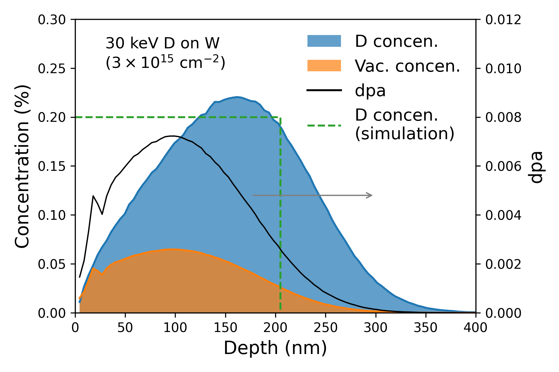
Based on the information obtained from SRIM calculations, the maximum depth of tungsten targets used in the NRA/C simulations was set to 205 nm, which is larger than the average range of 30 keV deuterium (154.4 nm), and is deep enough to cover most of the damaged region. Tungsten atoms were placed at perfect lattice positions. Since the depth resolution of NRA experiments is of the order of 100 nm [15], it is difficult to obtain a depth-resolved NRA experimental signals from a region with a thickness of 205 nm. Thus, the deuterium atoms in the simulation targets were set to have a uniform distribution along the depth as shown in Fig. 1 (green line). The concentration of deuterium atoms was set to 0.2 % (close to the maximum concentration in the experiments). The lattice locations of deuterium atoms were determined from the DFT calculations. In this process, we take into account that, for every deuterium atom, there are three equivalent positions when it is viewed from the three different <001> directions. Since, as shown in Fig. 1, the maximum vacancy concentration (0.065 %) induced by the irradiation is fairly small, defective structures were not introduced in the simulation targets. This small amount of defects should not have a significant effect on the movement of probing ions.
2.3.2 Setup of NRA/C simulations
As in the P-V experiments, 750 keV 3He ions were applied to probe the tungsten simulation targets along the [001] direction. Deuterium atoms in the targets were detected using the nuclear reaction D(3He,p)4He. A detector was located at 135∘ to detect the emitting protons from the reaction. The energy resolution of the detector was set to 16.5 keV. Differential cross sections of D(3He,p)4He measured at 135∘ [55] were used. The simulation temperature and the Debye temperature of the tungsten targets were 290 K and 377 K, respectively [68], which gives a 1D thermal vibration magnitude of tungsten atoms equal to 4 pm. The 1D thermal vibration magnitude of deuterium atoms was set to 14 pm [16]. The spread angle of emitting protons was set to 0∘, resulting in little effect of multiple scattering.
Angular scans across the [001] axis were performed by gradually increasing the polar angle between the direction of the incident beam and the [001] direction. Results of angular scans can depend on the azimuthal angle between the incident beam and crystal axis as well. However, the azimuthal angle was not reported in the P-V experiments. Hence, for every polar angle, we accumulated NRA/C signals by varying the azimuthal angle from 0∘ to 359∘ with 1∘ as the increment. Thus, the simulation results at the negative polar angle region are a reflection of those at the positive region. The validity of this approach is presented in the Results section.
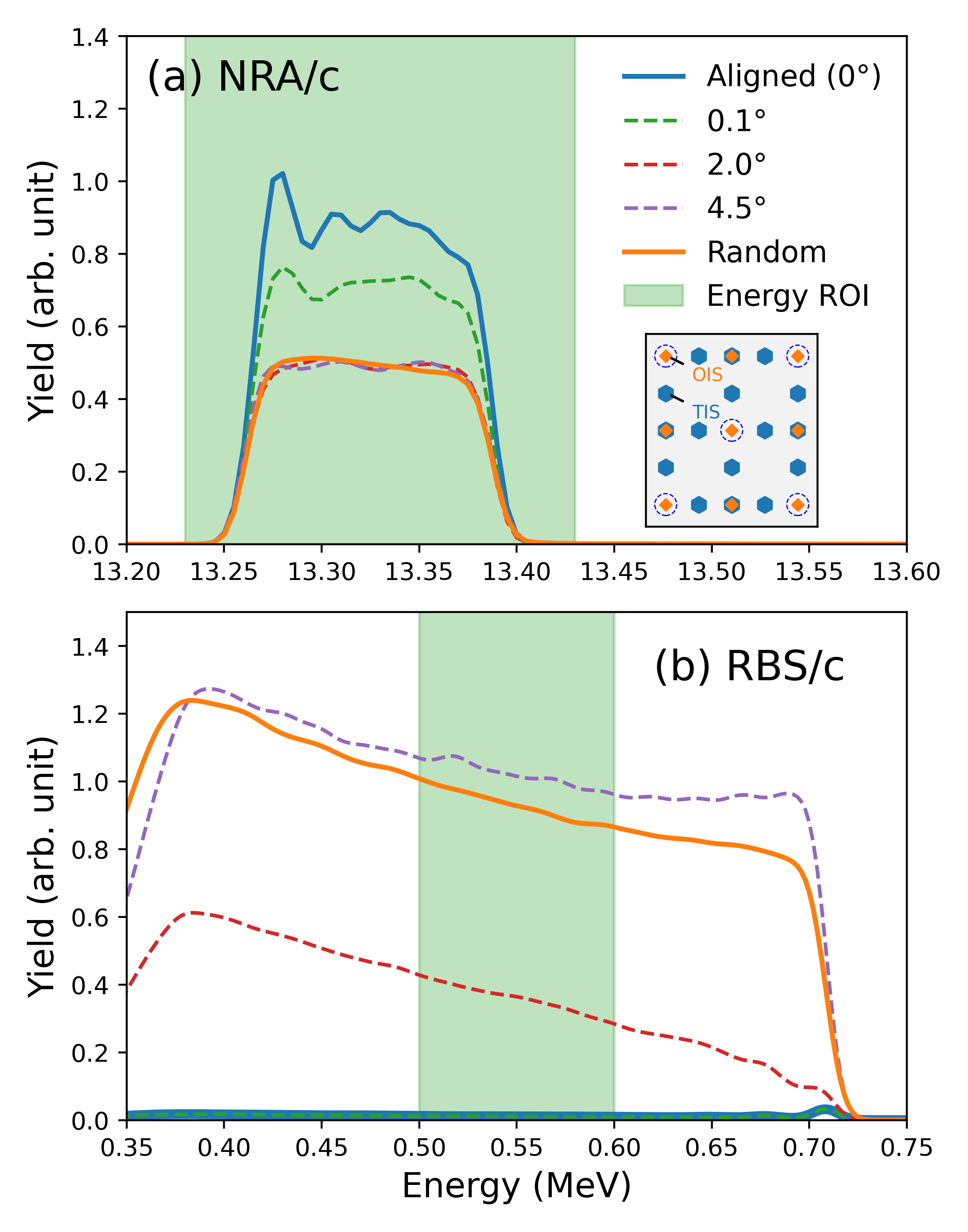
An example of NRA/C spectra of 750 keV 3He ions on tungsten containing 0.2 % deuterium located at TIS are displayed in Fig. 2a. The yield of spectra is highest when the incident beam is well aligned with the [001] axis (blue solid line), and decreases with a higher polar angle (dashed lines). We can observe an oscillation of the yield on the left side of the aligned spectrum. This is because the spatial distribution of 3He ions is not yet stable at the surface region. (Note the NRA/C signals generated from the surface region is at the low energy side of spectra.) In terms of angular scans, at each polar angle, the total yield of a whole spectrum was calculated, as indicated by the colored region of interest (ROI) in Fig. 2a. Subsequently, the results were normalized by the total yield obtained from a random configuration (orange solid line), in which all the atoms in the simulation targets were randomly displaced.
2.3.3 Setup of RBS/c simulations
The setup of RBS/c simulations is similar to that of NRA/C simulations. 750 keV 3He ions were applied to probe the tungsten simulation targets along the [001] direction. For RBS/c simulations, no deuterium is introduced to the simulation targets. 3He ions backscattered from tungsten atoms were detected by a detector located at 135∘ with an energy resolution of 16.5 keV. The 1D thermal vibration magnitude of tungsten atoms was 4 pm as in the NRA/C part.
Fig. 2b shows example RBS/c spectra obtained at different polar angles and at the random configuration. The yield increases with a higher polar angle. For angular scans, the total yield in an energy range of 0.5 MeV to 0.6 MeV was calculated, and was subsequently normalized by that in the random configuration.
3 Results
In this section, we show the variation of hydrogen lattice locations at different trapping conditions, and how this location variation affects the NRA/C signals. These results can be used as a comprehensive database for interpretation of NRA/C spectra with respect to their response to different types of deuterium trapping conditions.
For each trapping condition, we compare the simulated NRA/C signals to that of P-V experiments, and assess the possibility of corresponding scenarios by taking into account the behavior of deuterium/hydrogen at room temperature in terms of solubility and binding energies. The analysis of trapping conditions starts with deuterium/hydrogen in perfect tungsten, followed by deuterium/hydrogen bonding to defects of interstitial and vacancy type.
3.1 Deuterium/Hydrogen in perfect tungsten
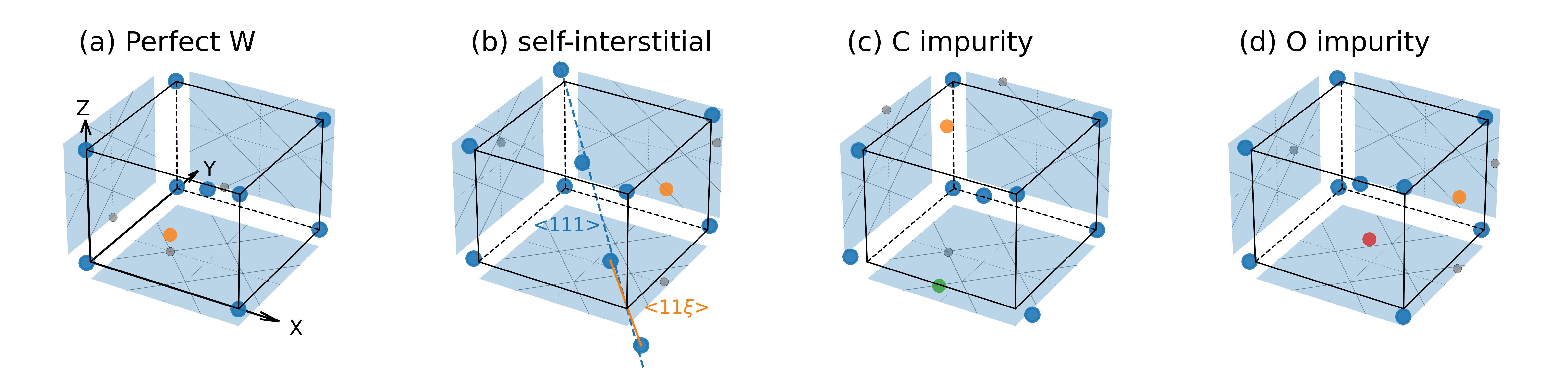
The most stable site of a hydrogen atom in the perfect tungsten is at the TIS, as shown in Fig. 3a, which is in agreement with other works [69, 41]. The formation energy (or the solution energy) at the TIS, , is 0.96 eV. After taking into account the ZPE correction, equals to 1.07 eV. (Three vibration frequencies of hydrogen at the TIS are 1571.6, 1568.8, 1166.5 cm-1, respectively. The method of calculating ZPE is given in Sec.2.1.) A comparison of the formation energy of this work to that of other works and experiments can be found in Table.I. As compared to the TIS, the hydrogen atom at the OIS has a higher formation energy ( eV). In fact, the vibration of hydrogen at the OIS has one real frequency and two imaginary frequencies (2521.2, and cm-1). Thus, the hydrogen at the OTS is at a second order saddle point as reported in other works [41]. In the following, when we calculate binding energies of hydrogen to defects, we consider that the hydrogen comes from a TIS far away from the defect.
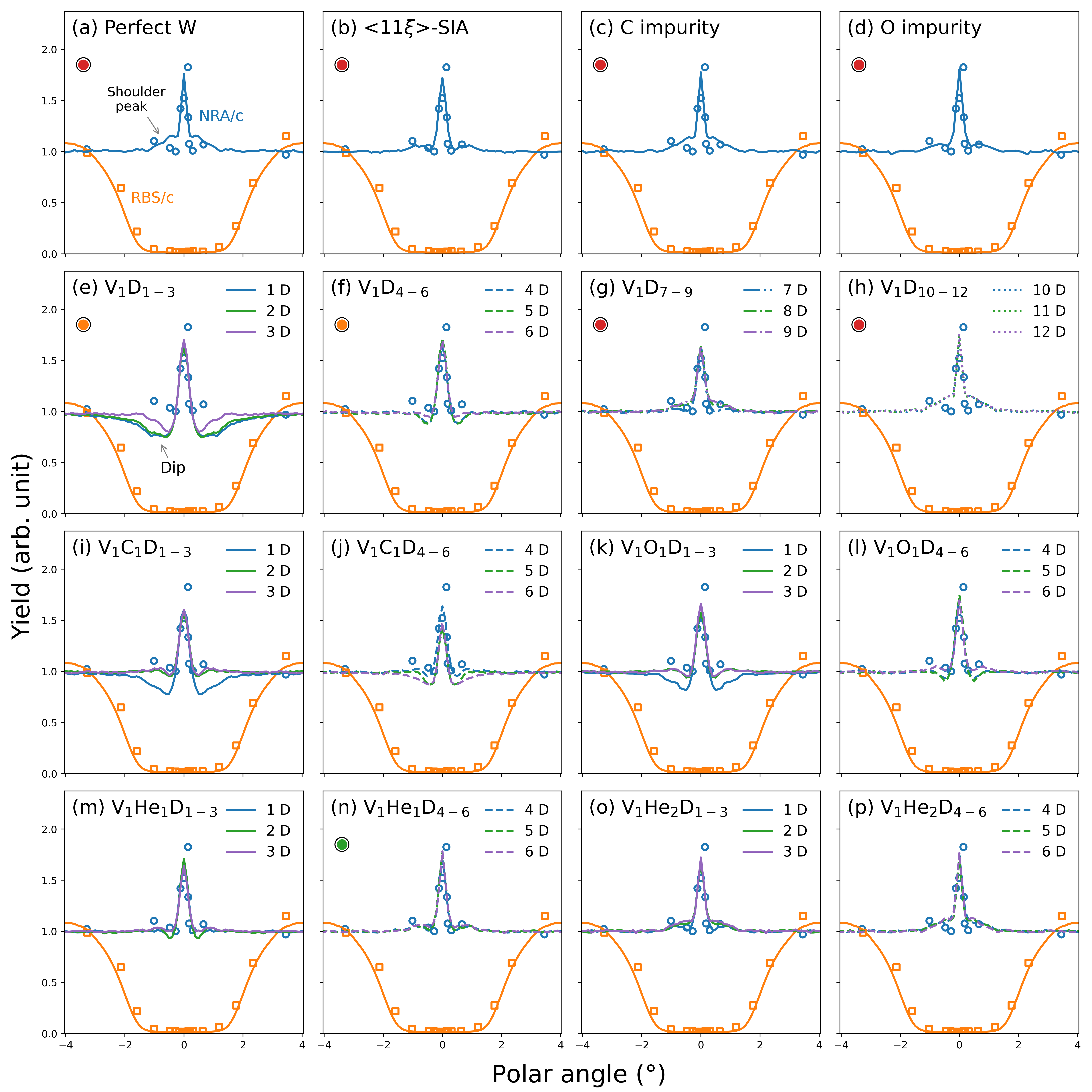
Simulation results of angular scans through the [001] axis of tungsten are represented by lines in Fig. 4a, in which the results of P-V experiments are represented by markers. For RBS/c simulations, the results were obtained by using perfect tungsten. The RBS/c simulation and experimental results share a good agreement, indicating the validity of the simulation method of angular scans.
For NRA/C simulations, the signals were generated from a tungsten sample with deuterium atoms located at the TIS. The simulation results are close to those of P-V experiment. Both results feature a central peak at 0 ∘, implying that there are deuterium atoms located at the center of the [001] channel. With a larger polar angle, we can observe two relatively small shoulder peaks on the two side of central peak. This should be attributed to deuterium atoms lying between the center of [001] channel and the row of tungsten atoms. However, the shoulder peaks in the P-V experiments are located at a larger angle than those in the simulations. Thus, the deuterium atoms in the P-V experiments are slightly displaced from the TIS.
Although the simulation and experimental results seem to agree well except for some minor differences, the major contribution to experimental signals obtained at room temperature should not be due to the deuterium dissolved in tungsten because of the reasons discussed in the introduction (low solubility and high migration rate). Most likely, the deuterium in the P-V experiments were attracted to defective structures. To explore this possibility, we consider next H atoms bonded to intrinsic defects.
| Present DFT | Other DFT | Experiments | |
| Lat. para. (Å) | 3.172 | 3.172 [38] | 3.165 [70] |
| 3.38 | 3.34 [38], 3.23 [31] | 3.67 0.2 [71] | |
| 10.49 | 10.256b [72] | ||
| 0.96 (1.07)a | 0.95 [69], 0.93 (1.04)a [41] | 1.040.17 [26] | |
| 1.35 | 1.34 [69], 1.37 [41] | ||
| a The value in the parenthesis is from calculations taking into account the ZPE correction. | |||
| b The value is from calculations using supercells in ref.[72]. | |||
3.2 Deuterium/Hydrogen bonding to defects of interstitial type
We investigated the hydrogen bonding to a self-interstitial atom (SIA) in the dumbbell configuration, which has been demonstrated to be the most stable configuration [72]. This configuration is geometrically close to the interstitial configuration with being an irrational number. In addition, since carbon and oxygen are major impurity atoms in tungsten [4], scenarios of hydrogen bonding to carbon and oxygen were also studied.
The formation energy of the SIA according to our calculation is 10.49 eV. The value of is close to 0.4, and the angle between the and direction is 19.4 ∘. A comparison with that determined from other calculations is given in Table.I. To study the position of a hydrogen bonding to the SIA, a hydrogen atom was initially placed in the vicinity of SIA. After relaxation, the hydrogen atom is located at a position close to the TIS as shown in Fig. 3b, which is displaced by 0.22 Å from the TIS towards OIS. (The distance between the TIS and OIS is 0.793 Å.) The distance of the hydrogen atom to the center of SIA is 2.60 Å. The binding energy of hydrogen to the SIA is 0.23 eV (0.28 eV after taking into account the ZPE correction). We have also explored the scenarios of placing a hydrogen atom at the vicinity of SIA. After relaxation, the SIA is distorted and transforms to SIA. The hydrogen atom is still close to the TIS. Distortion of SIA by hydrogen atoms has also been reported in other studies [38].
In terms of the impurity atoms, carbon prefers to occupy the OIS in a perfect tungsten. If we put a carbon atom at a TIS, it moves to an OIS after position relaxation. On the contrary, the stable position for oxygen is the TIS. These results are in agreement with those reported in other works [73, 74, 75]. As in the case of <111> SIA, a hydrogen atom was initially placed in the vicinity of a carbon atom. After position relaxation, the hydrogen atom is almost located at the TIS (displaced by 0.03 Å from the TIS to OIS). The distance between the hydrogen and carbon atom is 3.60 Å. The binding energy in this case is very weak, 0.05 eV (0.06 eV with the ZPE correction). The hydrogen bonding to an oxygen atom is displaced by 0.16 Å from the TIS towards OIS. The distance and the binding energy between the hydrogen and oxygen atom are 2.24 Å and 0.24 eV (0.26 eV with the ZPE correction), respectively. Fig. 3c and Fig. 3d show the positions of hydrogen bonding to the carbon and oxygen atom, respectively.
NRA/C results for deuterium bonding to the SIA, carbon and oxygen atom are shown in Fig. 4b, Fig. 4c and Fig. 4d, respectively. Since the positions of deuterium in these cases are close to the TIS, the simulation results appear to have good agreement with the experimental ones, especially for the cases of SIAs and oxygen. However, the binding energy of deuterium/hydrogen to SIAs is low. It has been shown that the detrapping temperature of hydrogen bonding to a SIA is lower than room temperature (below 200 K) [38]. Also the SIA itself is extremely mobile even at cryogenic temperatures, and it is very unlikely that isolated SIAs would be present in experimental samples [76] (indeed, field ion microscopy experiments have observed vacancies, but not interstitials in tungsten [77, 78]). Similarly, we can expect a low detrapping temperature for hydrogen bonding to a carbon and oxygen atom. In fact, the binding energy of hydrogen to these defects depends on the distance, and remains at a relatively small level [75, 32]. Thus, we can suggest that the signals in the P-V experiments are mainly contributed by deuterium trapped by other types of defects.
3.3 Deuterium/Hydrogen bonding to vacancies
The energy of deuterium atoms (30 keV) in the P-V experiments is high enough to create vacancies. Considering that the maximum concentration of vacancy is low (0.065 %) as presented in Fig. 1 and the migration energy of a vacancy is high (1.71 eV from ref.[38]), it is fair to assume that at room temperature the vacancies in the experimental samples will be present mainly as monovacancies [67]. Hence, in the present study we investigated the scenarios with multiple hydrogen atoms trapped in a mono-vacancy.
The formation energy of vacancy according to our calculations is 3.38 eV. A comparison of the formation energy for this work to that of other works and experiments can be found in Table I. Hydrogen atoms were introduced to a vacancy by two methods. In the first method, the initial positions of hydrogen atoms were randomly selected inside a vacancy. In the second method, we introduced the hydrogen atoms following the stable structures proposed by Ohsawa et al [40]. After positions relaxation, we took the structure with a smaller energy obtained from the two methods. It turns out that the distributions of hydrogen atoms with minimum energies, as shown in Fig. 5, are similar to those in the work of Ohsawa et al [40].
Fig. 6a illustrates the positions of hydrogen atoms bonding to a vacancy with different filling levels, in terms of the relative distance to the OIS and TIS. The notation V1Hi represents hydrogen atoms bonding to one vacancy. When there is only one hydrogen atom bonding to the vacancy, the hydrogen atom occupies a position close to the OIS. It is slightly displaced by 0.10 Å from the OIS towards the TIS, and has a distance of 0.32 Å with the closest vacancy surface (a (001) plane). When there are two hydrogen atoms, the hydrogen atoms occupy positions nearby the OIS, but are located at two opposite planes instead of being at the same plane. This distribution can be attributed to a generally repulsive nature of hydrogen-hydrogen interaction at short distances inside tungsten [30]. With a higher number of hydrogen atoms, hydrogen atoms start to occupy remaining empty planes surrounding the vacancy. Each plane holds one hydrogen atom until there is a total number of 6 hydrogen atoms in the vacancy. Noticeably, the stable position of hydrogen atom is gradually shifted from the OIS towards the direction of TIS. When the trapping number is 6, the hydrogen atoms are distributed around the midpoint of the OIS and TIS.
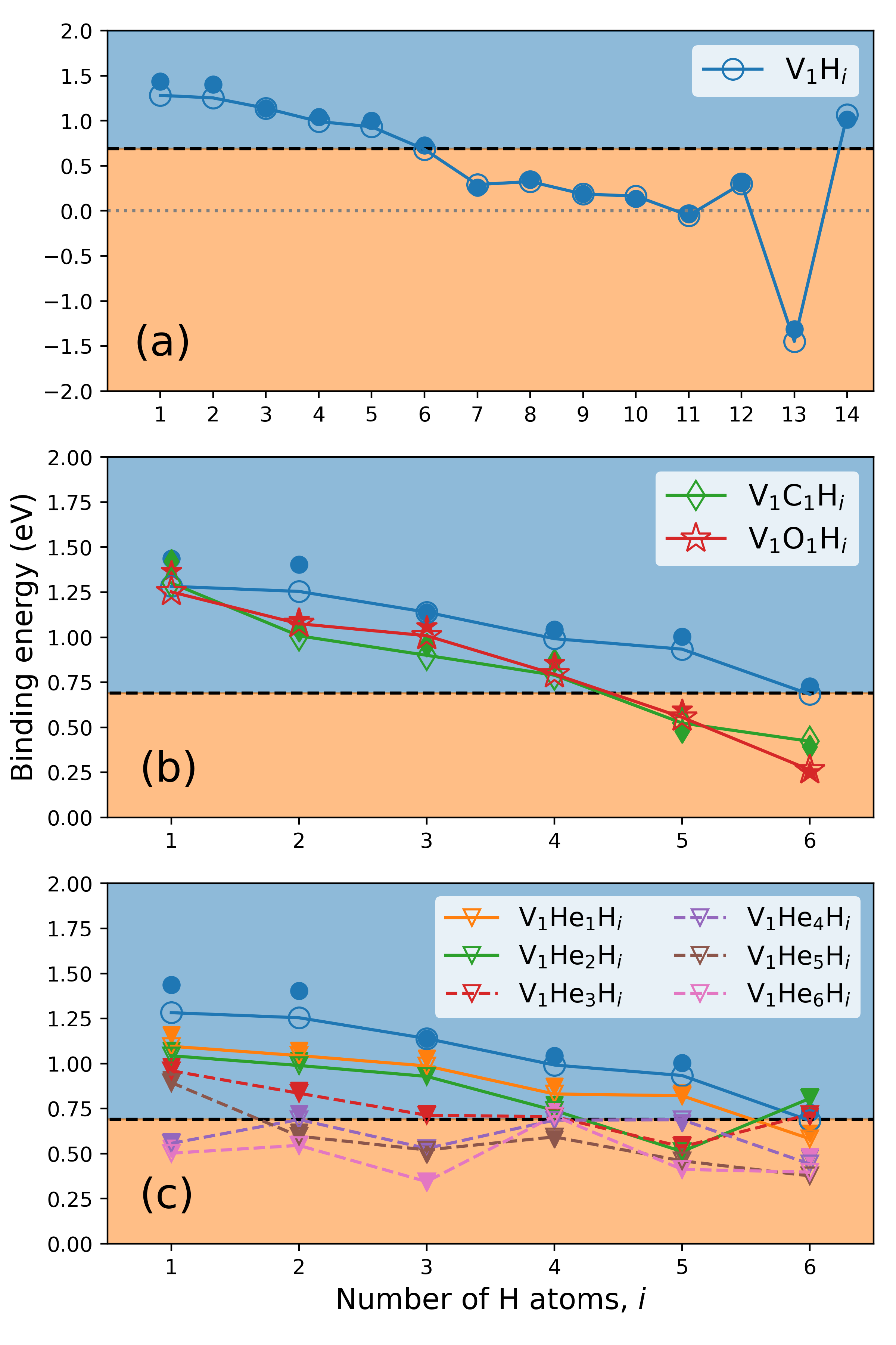
When the total number of hydrogen atoms in the vacancy is larger than 6, some planes surrounding the vacancy start to accommodate two hydrogen atoms, in which case the two hydrogen atoms are located at positions close to the TIS. Thus, when 12 hydrogen atoms are trapped by the vacancy, each plane accommodates two hydrogen atoms, and all the hydrogen atoms are basically positioned at the TIS. The binding energy of hydrogen to the vacancy gradually diminishes with a higher number of hydrogen atoms as given in Fig. 7a, in which the binding energy denoted by VHi represents the binding energy of a hydrogen atom located at a TIS far away from the vacancy to a vacancy containing hydrogen atoms (the binding energies without and with the ZPE correction are represented by the blue hollow and filled circles, respectively). The results indicate that a vacancy can hold up to 12 hydrogen atoms. In case that 14 hydrogen atoms are introduced to a vacancy, a hydrogen molecule is formed, resulting in an increase of binding energy. These features are in line with those reported in other works [40, 41]
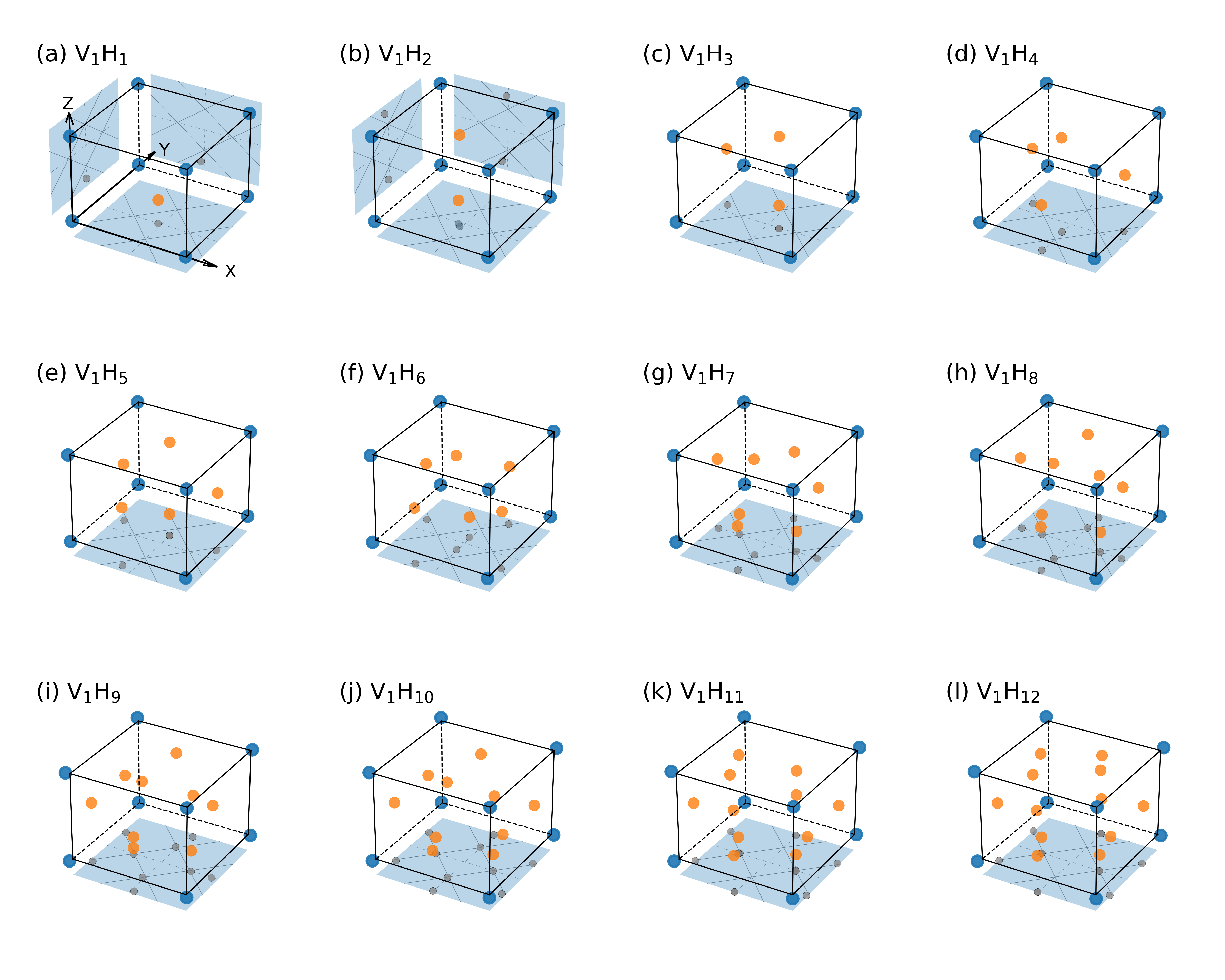
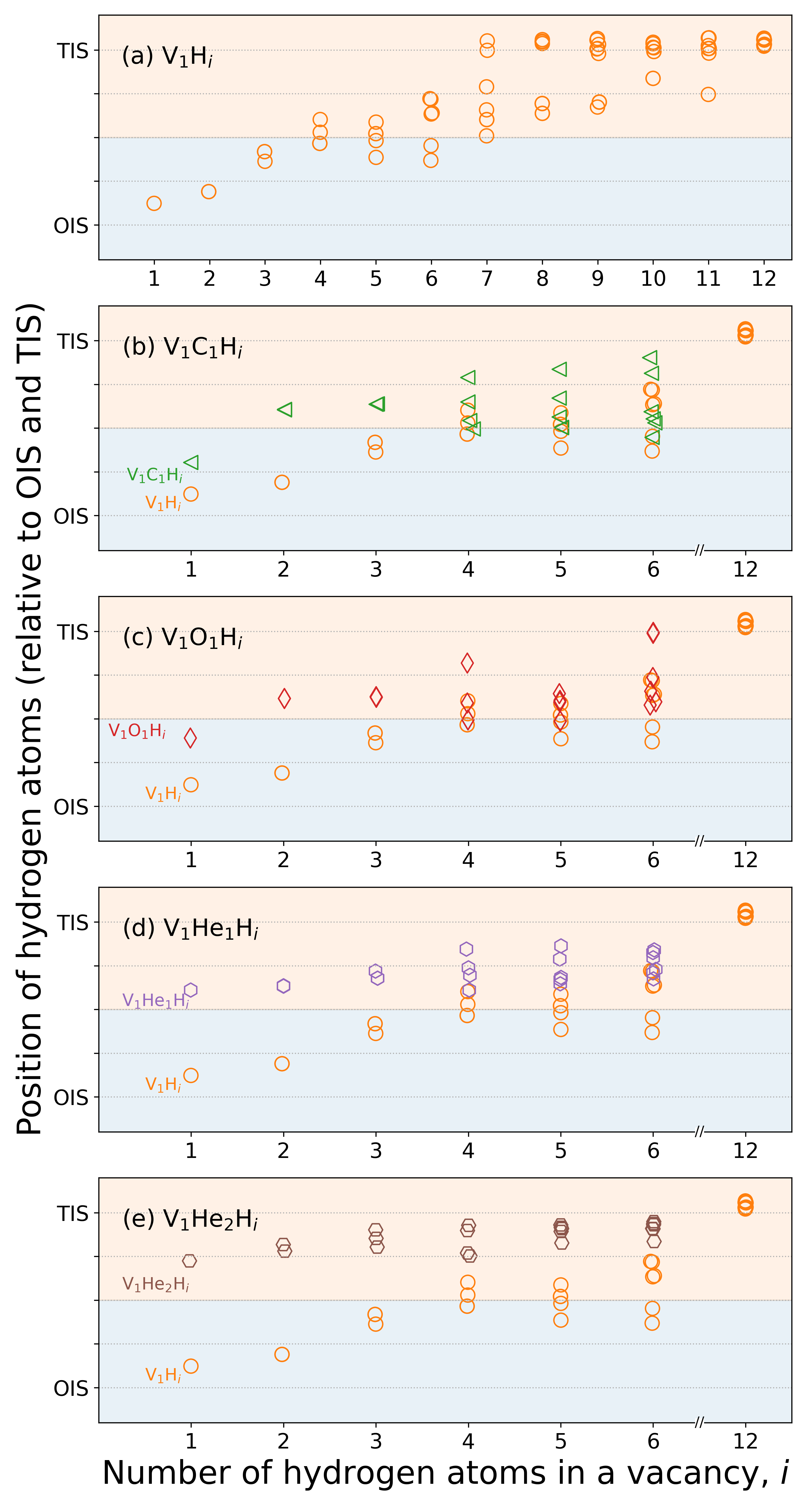
Fig. 4(e-h) show NRA/C results of a vacancy containing up to 12 deuterium atoms, which exhibit distinct features with different filling levels of deuterium. For the cases of V1D1-3, the NRA/C results exhibit significant differences with that of deuterium in perfect tungsten, as shown in Fig. 4a as well as to the P-V experiments. This is because, in the cases of a vacancy containing 1 to 3 deuterium atoms, the deuterium atoms are close to the OIS, and 1/3 of OISs are covered by tungsten atoms viewed along the [001] direction. Thus, instead of shoulder peaks shown in Fig. 4a (in which deuterium atoms are at the TIS), we can observe dips at the two sides of the central peak. More specifically, for the case of V1D3, the dips become narrower because the deuterium atoms are displaced from the OIS by a larger distance.
By further increasing the number of deuterium atoms in the vacancy, it can be clearly observed that the signals of dips fade as shown in Fig. 4f. For the case of V1D6, the dips almost disappear, and the NRA/C signals feature only a central peak. When the total number of deuterium is larger than 6, the signals of shoulder peaks are gradually built up as shown in Fig. 4g. Finally, the NRA/C signals become stable for the cases of a vacancy containing 10 to 12 deuterium atoms as shown in Fig. 4h, and are similar to that of deuterium in perfect tungsten shown in Fig. 4a.
Comparing the NRA/C simulation and the P-V experiments, the spectra obtained with vacancies containing more than 6 deuterium atoms are consistent with experiments. However, it has been suggested that the filling level of deuterium/hydrogen in a vacancy is only 6 at room temperature according to the calculation performed by Fernandez et al. [41]. By assuming a threshold binding energy to be 0.69 eV (which is the binding energy of V1H6 according to the results given by Fernandez et al. [41]), we can divide the trapping of deuterium/hydrogen in a vacancy to two categories, as indicated by the blue and orange regions in Fig. 7. Clearly, the binding energies of a vacancy containing 7 to 12 deuterium/hydrogen atoms are smaller than the threshold. Hence, it is less likely that in the P-V experiments vacancies were containing more than 6 deuterium atoms.
At this stage, we have excluded a number of trapping conditions based on the evaluation of binding energy. Only remaining scenarios are the cases of a vacancy containing 1 to 6 deuterium atoms. Yet, the NRA/C signals of the remaining scenarios are clearly different with the P-V experiments. Note that this difference does not mean that the deuterium atoms are not trapped by the vacancies in the experiments. Instead, it indicates that there must be some additional factors affecting the positions of deuterium, for example, impurity atoms in the vacancy.
3.4 Deuterium/Hydrogen bonding to vacancies with carbon or oxygen
Carbon and oxygen show high binding energies to a vacancy, 2.16 eV and 3.26 eV according to our calculations, respectively. Inside a vacancy, both atoms prefer to occupy a position close to the OIS, which is in agreement with that reported in other works [75]. We introduced up to 6 hydrogen atoms in vacancies containing a carbon or oxygen atom. The introduction method is the same to that presented in previous section. The corresponding binding energies are given in Fig. 7b, in which the notation V1C1Hi (V1O1Hi) represents a vacancy containing hydrogen atoms and a carbon (oxygen) atom.
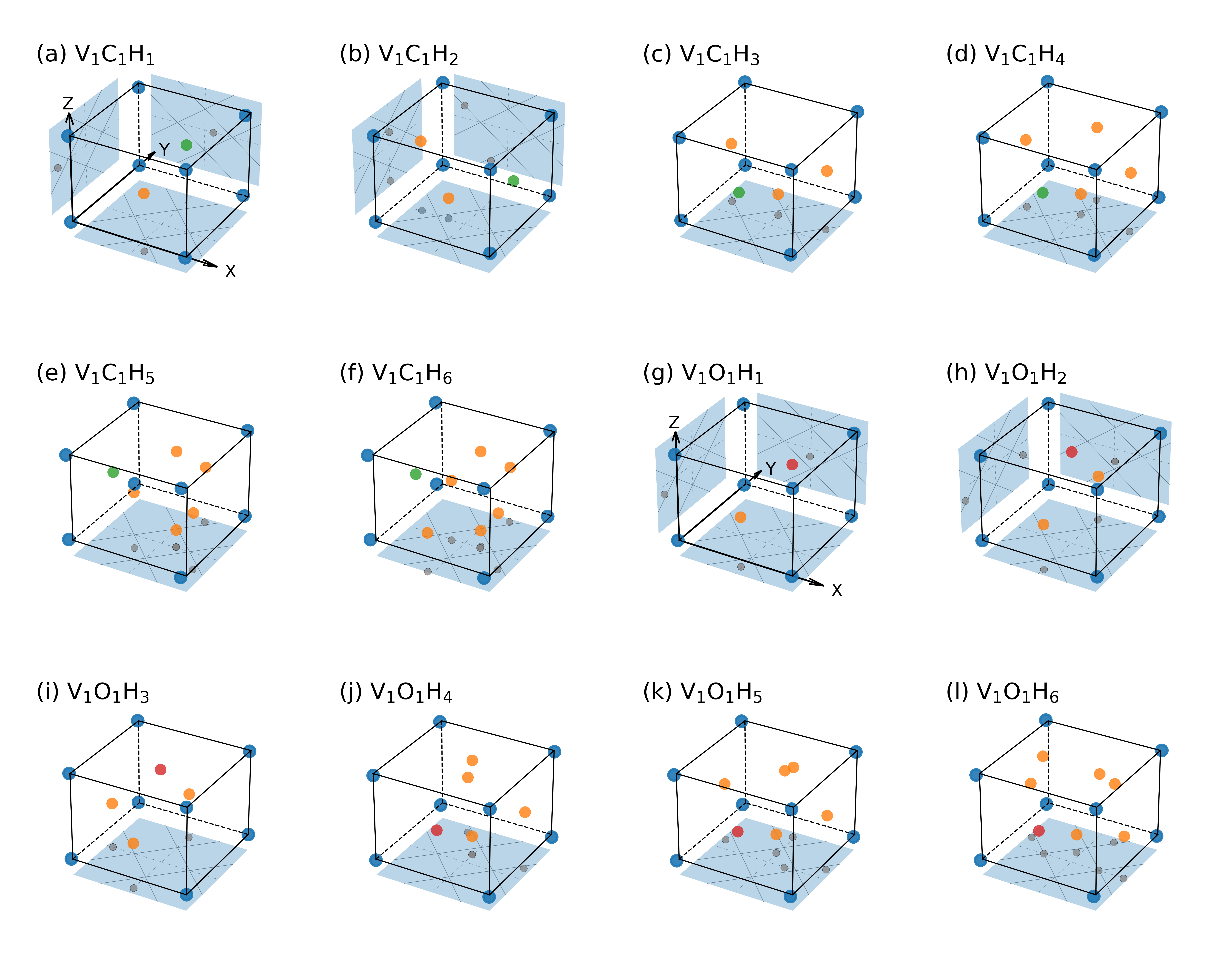
The positions of hydrogen atoms in a vacancy containing a carbon atom are shown in Fig. 8(a-f). Fig. 6b illustrates the relative positions of hydrogen atoms between the OIS and TIS. The corresponding NRA/C results are shown in Fig. 4(i-j). The insertion of a carbon atom into a vacancy indeed affects the stable positions of hydrogen atoms. For the case of V1C1H1, the hydrogen atom is still close to the OIS, but the distance to the OIS becomes larger compared to the case without carbon. This displacement is reflected from the narrower NRA/C dips in Fig. 4i compared to that in Fig. 4e. When the number of hydrogen atoms is increased to 3, the hydrogen atoms are further displaced towards the TIS. The corresponding NRA/C results are featured with small shoulder peaks as shown in Fig. 4i.
However, when the number of hydrogen atom is increased from 4 up to 6, the configuration of hydrogen atoms become spread: some hydrogen atoms get closer to the TIS, but some are slightly displaced backwards towards the direction of OIS as shown in Fig. 6b. In addition, for the cases of V1C1H5 and V1C1H6 hydrogen atoms, one hydrogen atom is located between the carbon atom and vacancy center instead of the vacancy surface. As shown in Fig. 4j, due to the spread of deuterium/hydrogen atoms, from V1C1H4 to V1C1H6, the central peak of NRA/C slightly diminishes accompanied by a recurrence of dips.
The positions of hydrogen atoms in a vacancy containing an oxygen atoms are shown in Fig. 8(g-l). Fig. 6c illustrates the relative positions of hydrogen atoms between the OIS and TIS. The corresponding NRA/C results are shown in Fig. 4(k-l).The oxygen atom affects the positions of hydrogen atoms in a similar way as the carbon atom. From V1O1H1 to V1O1H3, the hydrogen atoms are shifted towards the TIS. As a result, we can observe a transformation of dips to small shoulder peaks in the NRA/C results (see Fig. 4k). When there are 4 and 5 hydrogen atoms, the positions of hydrogen atoms are spread around the midpoint of OIS and TIS. For the case of 6 hydrogen atoms, two hydrogen atoms are positioned on a same vacancy surface and occupies TISs. Thus, the corresponding NRA/C results, as shown in Fig. 4l, exhibit shoulder peaks instead of dips as in the case of V1C1H6 (see Fig. 4j).
In general, after considering the effect of carbon and oxygen atoms, the agreement between the NRA/C simulation and experiments is improved. Nonetheless, the central peaks in the cases of V1C1Di are clearly lower than those in the experiments. For the cases of V1O1Di, the NRA/C result generated from a vacancy containing 6 deuterium atoms shows the best agreement with the experiment. However, the binding energy for this case is lower than the threshold binding energy as shown in Fig. 7b, implying a possible detrapping of deuterium/hydrogen atoms at room temperature. Again, we need to mention that as long as the binding energies are high, the corresponding scenarios are possible. Nonetheless, in order to get a better agreement between NRA/C simulations and experiments, we propose to investigate the effect of another element, i.e., helium.
3.5 Deuterium/Hydrogen bonding to vacancies with helium
A helium atom in a perfect tungsten prefers to occupy the TIS with a formation energy of 6.14 eV (6.23 eV with the ZPE correction), in agreement with other DFT calculations [79]. It has also been shown that a single tungsten vacancy can accommodate at least 9 helium atoms [80]. Here, we investigated the scenarios of a vacancy containing from 1 to 6 helium atoms. Contrary to hydrogen, our calculations show that the preferential position of a helium atom in a vacancy is at its center, which is in line with other studies [81].
Increasing the number of helium atoms in a vacancy did not change the trend: the helium atoms still gathered close to the vacancy center. The configurations of multiple helium atoms in a vacancy exhibit high symmetry features. From 2 to 6 helium atoms, the helium atoms are organized in a shape of <111>-oriented dumbbell, equilateral triangle (with a side length of 1.53 Å), regular tetrahedron (with a side length of 1.56 Å), triangular bipyramid and regular octahedron (with a side length of 1.57 Å), respectively. Here, we show the cases of a vacancy containing up to 2 helium atoms and multiple hydrogen atoms. The cases of a vacancy containing 3 to 6 helium atoms are presented in the supplementary materials. The notation V1HenHi, represents a vacancy containing helium atoms and hydrogen atoms.
We found that it is prone for a vacancy complex containing both helium and hydrogen atoms to form a meta-stable structure. Thus, when we introduce hydrogen atoms to the vacancy complex, in addition to the method used in Sec.3.3, we assume that, in general, the binding energy of a hydrogen atom to the vacancy complex decreases with a higher number of hydrogen and helium atom. For cases against this assumption, we perform additional calculations by adjusting initial positions of atoms in the vacancy.
Stable positions of hydrogen atoms for the cases of V1He1Hi and V1He2Hi are given in Fig. 9(a-f) and Fig. 9(g-l), respectively. Fig. 6d and Fig. 6e illustrate the relative positions of hydrogen atoms between the OIS and TIS for the cases with one and two helium atoms, respectively. The corresponding binding energies are shown in Fig. 7c, in which the binding energies for vacancies containing 3 to 6 helium atoms are also displayed. The binding energies of V1He1Hi and V1He2Hi follow the assumption mentioned before (the binding energy decreases with more hydrogen and helium atoms) except the case of V1He2H6. One plausible reason is that the configuration of hydrogen atoms in this particular case possesses a higher symmetry compared to that of V1He2H5.
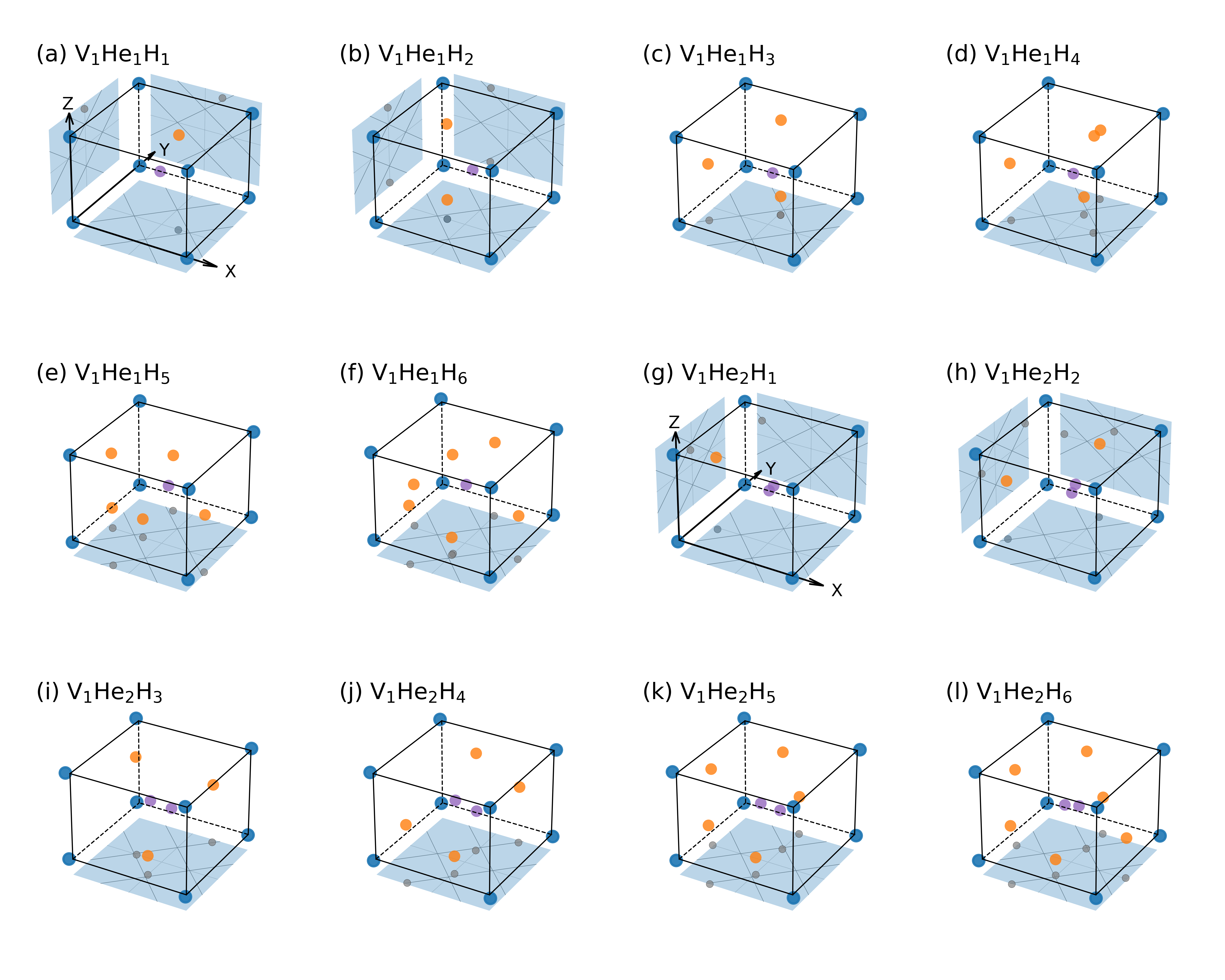
For the case of V1He1H1, the hydrogen atom is closer to the TIS (displaced by 0.48 Å from the OIS to TIS). This is in line with other DFT calculations showing hydrogen atoms prefer to occupy TISs instead of OISs [82]. By increasing the number of hydrogen atoms to 3, we can observe a shorter distance between the hydrogen atoms and TIS. The corresponding NRA/C results are given in Fig. 4m, in which there is a significant shrink of dips compared to the cases without helium atoms (see Fig. 4e). For the cases of V1He1H4-6, the stable positions of hydrogen atoms are further adjusted towards the TIS. The corresponding NRA/C results are featured with small shoulder peaks resembling the experimental ones as shown in Fig. 4n.
After introducing the second helium atom to above vacancies, the distance of hydrogen atoms and the TIS becomes smaller. Noticeably, the relative positions of hydrogen atoms are modified in some cases. For the case of V1He2H2, the configuration of 2 hydrogen atoms located at two adjacent vacancy surfaces as shown in Fig. 9h has a lower energy than a metastable configuration in which 2 hydrogen atoms are located at two opposite surfaces. For the case of V1He2H4, the relative positions of hydrogen atoms are also re-distributed as shown in Fig. 9j (the hydrogen atoms are at two opposite (001) planes and two opposite (010) planes) compared to that in Fig. 9d (two opposite (001) planes and adjacent (100) and (010) planes). In terms of the corresponding NRA/C results as shown in Fig. 4o and Fig. 4p, the signals of shoulder peaks are enhanced as compared to those in the cases of one helium atom. For vacancies containing more helium atoms (up to 6 helium atoms), the hydrogen atoms are still near the TIS, which are presented in the supplementary materials.
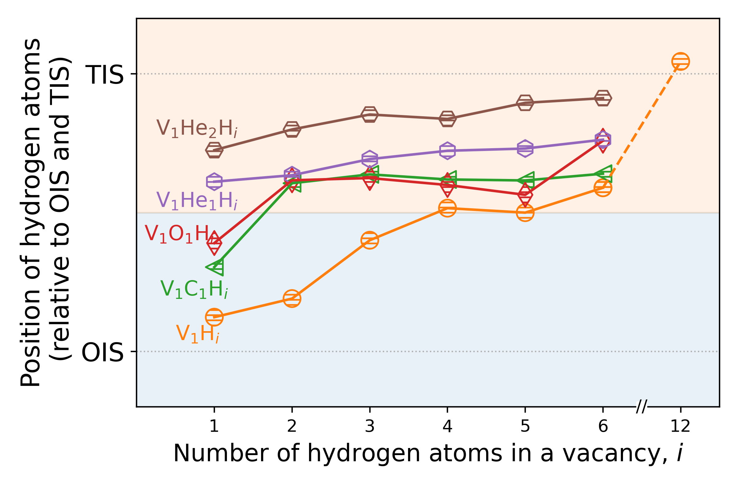
Fig. 10 shows the average positions of hydrogen atoms bonding to different types of vacancy complex. It can be clearly observed that the hydrogen atoms are closer to the TIS in vacancy complex containing impurities (including carbon, oxygen and helium) compared to those without impurities. Among these impurity atoms, the effect of helium atoms is most significant. The NRA/C results from the cases of V1He1D4-6 (see Fig. 4n) exhibit best agreement with that of P-V experiments. The case of V1He2D1 (see Fig. 4o) shows good agreement as well. However, the ratio of deuterium to vacancy is smaller than that predicted by SRIM and MD calculations presented in Sec.2.3.1. After taking into account the binding energy, the case of V1He1D6 becomes less favorable, but the cases of V1He1D4 and V1He1D5 are still promising. Thus, we can predict that the signals of P-V experiments are mainly induced by vacancy complex containing both helium and hydrogen atoms.
Unlike carbon and oxygen which are intrinsic impurities in tungsten, the helium atoms should come from the probing beam of 750 keV 3He ions used in the NRA/C experiments. The authors of P-V experiments did not report the measurement fluence of 3He ions in their paper [17]. However, they reported a measurement fluence of 3He ions in another paper, which is cm-2 [9]. In nowadays NRA experiment, the measurement fluence of 3He ions is on the order of magnitude of cm-2 [83]. Hence, we can estimate that the fluence of 3He ions is comparable to or even higher than that of deuterium ( cm-2) in the P-V experiments. Due to high binding energies between helium and vacancies [84] and low migration energies of helium in tungsten ( 0.06 eV [85, 86]), the helium from the measurement beam can be readily trapped by vacancies containing deuterium, resulting in the change of deuterium lattice locations. In fact, Picraux and Vook did observe that profiles of NRA/C angular scans can be affected by a continuous irradiation of 750 keV 3He ions in another experiment [18]. A discussion of this experiment is presented in next section.
4 Discussion
In the previous section, we demonstrated that the contradictory results about the positions of deuterium/hydrogen in a vacancy indicated by the NRA/C experiments (close to the TIS) and that determined by DFT calculations (close to the OIS) can be resolved by considering the effect of helium atoms. In fact, in experimental conditions, there could be other potential factors affecting the positions of deuterium/hydrogen in a vacancy. It has been reported that the stable positions of hydrogen in a perfect tungsten can be influenced by anisotropic elastic strain [23]. Nonetheless, the effect of strain should be negligible due to the small amount of defects in the P-V experiments.
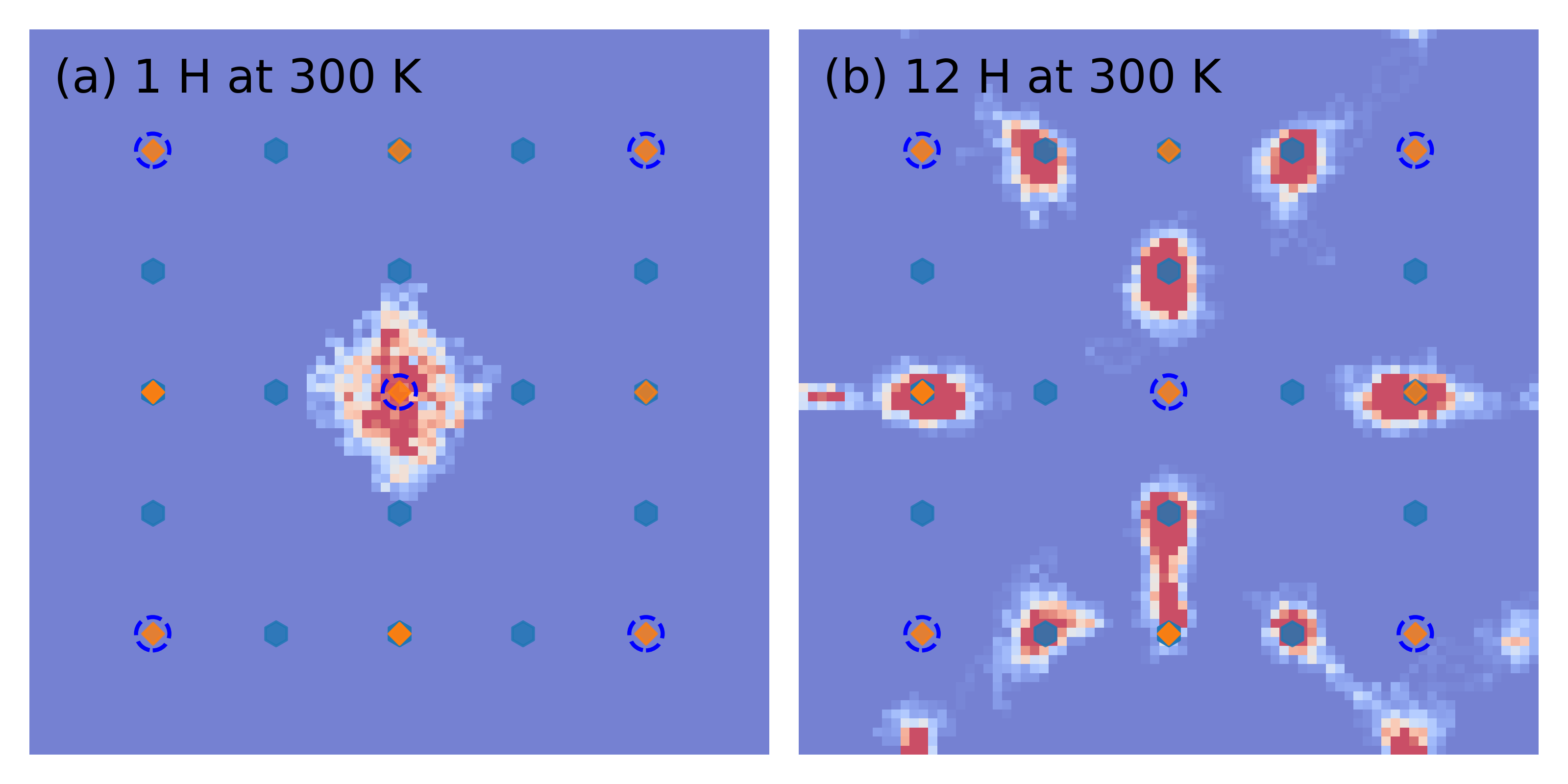
Another potential factor is the elevated temperature in the experiments. To this regard, we performed ab initio MD simulations at 300 K to investigate the movement of hydrogen atoms. The methods of ab initio MD simulations are given in supplementary materials. Fig. 11a and Fig. 11b show the probability density distributions of 1 and 12 hydrogen atoms bonding to a vacancy at 300 K, respectively. The simulation time is 4 ps. A warmer (colder) background color represents a higher (lower) possibility of finding hydrogen atoms at the corresponding position. For the cases of 1 and 12 hydrogen atoms, the hydrogen atoms are mainly vibrating around the OIS and TIS, respectively, which is in agreement with the DFT calculations. Hence, the elevated temperature at 300 K does not alter the stable positions of hydrogen in terms of the OIS and TIS. In addition, we can observe that, as shown in the right side of Fig. 11b, some hydrogen atoms are leaving from the vacancy, implying that the filling level of hydrogen in a vacancy at room temperature is smaller than 12.
In addition to the impact of helium, another major result from the study of deuterium lattice locations is related to the deuterium filling level. To collaborate and confront with NRA/C, we performed macroscopic rate equation (MRE) modelling to investigate the population of V1Di under the P-V experimental conditions prior to the application of 3He ion beam. The initial depth distribution of deuterium and the depth profile of vacancies follow the ones obtained from the SRIM and MD calculations shown in Fig. 1. The deuterium diffusion coefficient is taken from previous DFT calculations [41] with a diffusion barrier energy of 0.2 eV. The detrapping energies of deuterium from the vacancies were set to the binding energies given in Fig. 7 plus the diffusion barrier energy. 30 keV deuterium atoms were implanted to tungsten with a flux of cm-2s-1. After the fluence reached the P-V experimental one, the implantation was finished and the modelling entered to a resting period for 100 s at 296 K. Detailed mechanisms of the MRE modelling implemented in the MHIMS-R code can be found in previous works [87].
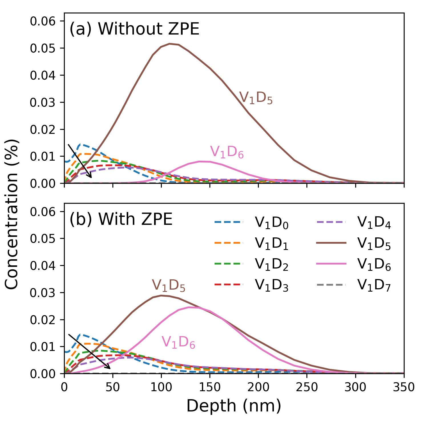
Fig. 12a shows the concentrations of V1Hi obtained from the MRE modelling after the resting period, in which the binding energies without the ZPE correction are used. We can observe that the dominant vacancy complex is V1H5. After taking into account the ZPE correction, as shown in Fig. 12b, the concentrations of V1H5 and V1H6 are on a similar level. The vacancy complexes with a filling level smaller than 5 are mainly populated at the near surface region. Whereas, there is almost no vacancy complex with more than 6 deuterium present in the target. In terms of the scenarios of V1He1Hi, our preliminary MRE modelling shows that the population of V1He1H6 significantly diminishes due to lower binding energy so that the only dominant structure is V1He1H5. Thus, we can find that the deuterium filling levels obtained from the NRA/C and MRE are in good agreement.
We have shown how different trapping conditions of deuterium atoms affects the deuterium lattice locations in the previous section. In turn, a variation of NRA/C results can indicate a change of deuterium lattice locations due to the evolution of defects. Fig. 13a shows the comparison of simulated NRA/C and RBS/c results to those of P-V experiments, in which the simulated NRA/C signals are generated from V1He1H5. Fig. 13b shows another NRA/C experiments performed by Picraux and Vook [18], in which 15 keV deuterium with a fluence of cm-2 were implanted to tungsten at room temperature. The probing ions are still 750 keV 3He ions. Initial results of NRA/C angular scan (red triangles) exhibit a central peak and prominent shoulder signals. The best agreement with the experiments is obtained from simulations (red line) generated from V1He3D3. This indicates that the deuterium lattice locations are already disturbed by the helium atoms. After the initial angular scan, Picraux and Vook performed another angular scan following additional irradiation of 750 keV 3He ions with a fleunce around cm-2 [18]. The experimental results of this second angular scan (purple triangles in Fig. 13b) exhibit significant difference with the first one. The yield of central peak decreases and signals of shoulder peaks are replaced by dips.
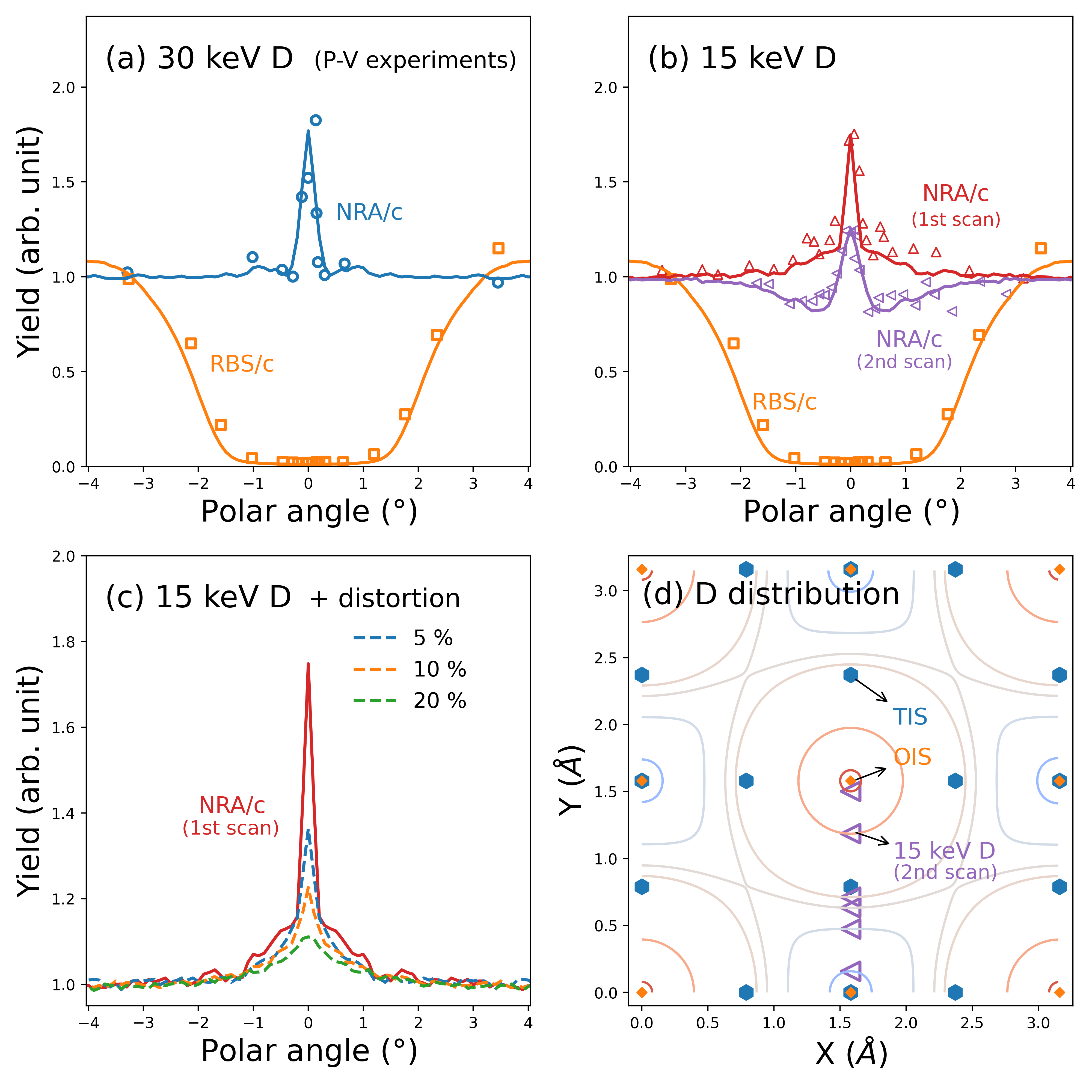
To study the trapping condition in the second angular scan shown in Fig. 13b, we simulated NRA/C signals by increasing the number of helium atoms in a vacancy up to 6. However, the simulated results cannot get a satisfactory agreement with the experimental ones. Furthermore, the binding energies of hydrogen atoms decrease with an increase of helium atoms (see Fig. 7), implying an easier detrapping of hydrogen atoms at room temperature. If fact, it has been postulated the evolution of NRA/C angular scans with additional helium irradiation can either be attributed to distortion on probing ions induced by the presence of large amount of helium atoms in tungsten [9] or due to an evolution of defects trapping deuterium atoms [36].
We studied the effect of distortion of probing ions on the first angular scan in Fig. 13b. The lattice locations of deuterium were kept fixed, but 5 % to 20 % of tungsten atoms were randomly displaced which can distort spatial distribution of probing ions in channeling mode. As shown in Fig. 13c, with a higher degree of distortion, the NRA/C central peak (dashed lines) diminishes, but there is no sign of formation of dips as in the case of the second scan in Fig. 13b. Hence, an evolution of trapping defects should be responsible for the change of NRA/C signals in Fig. 13b.
We found that the results of second angular scan can be fitted by simulations in which deuterium atoms (purple markers) are placed at locations as indicated in Fig. 13d. Since the spatial distribution of probing ions in a channeling mode is determined by a so-called continuum potential [88], deuterium atoms can be put at other positions with the same continuum potential which are indicated by the lines crossing deuterium atom shown in Fig. 13d. A general feature of the deuterium location is that the deuterium atoms are spread between the OIS and TIS. This feature may imply an evolution of defect types from isolated to extended ones, such as vacancy clusters providing large space for the decoration of deuterium atoms. One plausible mechanism for the formation of vacancy clusters can be trap mutation induced by large amounts of helium atoms [89]. DFT studies have shown that the stable positions of hydrogen atoms in di-vacancies are still close to the OIS [90]. Thus, we can expect that there could be larger extended defects. The cases of deuterium trapped by extended defects will be studied in the future.
The above studies suggest that it is important to have a clear record of the probing helium ions when one performs NRA/C experiments. This is not only to make the experiments possible to reproduce or simulate, but also to take into account the effect of helium atoms on defect evolution. For the design of NRA/C experiments, it would be preferable to increase the ratio between the total amount of deuterium and helium atoms.
5 Conclusions
In this work, we studied the lattice locations of deuterium in tungsten and the correlation of the lattice locations with trapping conditions. DFT calculations were used to determine the lattice locations of hydrogen at different trapping conditions. A newly developed NRA/C simulation software was applied to generate signals of NRA/C angular scans through the [001] axis of tungsten. We systematically produced the NRA/C signals for deuterium retained in perfect tungsten and trapped by defects of interstitial and vacancy type at different deuterium filling levels.
Our studies show that the trapping conditions affect the relative distance of deuterium to the OIS and TIS sites, resulting in distinct features in NRA/C signals. The comparison between NRA/C simulations and available experiments [17, 18] suggests that the deuterium atoms were trapped by vacancies, and their lattice locations is affected by helium from the probing beam used for NRA/C. Comparing with the DFT calculations, we find that the P-V experiments can be reproduced by the majority of deuterium having been trapped by the vacancy complexes V1He1H4 and/or V1He1H5. This prediction is in a good agreement with that obtained from macroscopic rate equation modelling, which favors the V1He1H5 vacancy complex.
More generally, our study demonstrates that by combining the NRA/C and DFT methods one can deduce the atomic nature of crystal structures trapping deuterium. This opens up the possibility to use further NRA/C experiments for different materials and/or hydrogen loading conditions to gain additional insight on hydrogen behaviour in metals.
Acknowledgements
X. Jin acknowledges Thomas Schwarz-Selinger, Huan Liu, Ilja Makkonen and Tommy Ahlgren for fruitful discussions. This work has been carried out within the framework of the EUROfusion Consortium, funded by the European Union via the Euratom Research and Training Programme (Grant Agreement No 101052200 — EUROfusion). Views and opinions expressed are however those of the author(s) only and do not necessarily reflect those of the European Union or the European Commission. Neither the European Union nor the European Commission can be held responsible for them. The authors wish to acknowledge CSC – IT Center for Science, Finland, for computational resources.
Competing interests
The authors declare no conflict of interest.
References
- [1] Sakintuna, B., Lamari-Darkrim, F. & Hirscher, M. Metal hydride materials for solid hydrogen storage: A review. Int. J. Hydrog. Energy 32, 1121–1140 (2007).
- [2] Song, J. & Curtin, W. A. Atomic mechanism and prediction of hydrogen embrittlement in iron. Nat. Mater. 12, 145–151 (2013).
- [3] Tiegel, M. C. et al. Crack and blister initiation and growth in purified iron due to hydrogen loading. Acta Mater. 115, 24–34 (2016).
- [4] Tanabe, T. Review of hydrogen retention in tungsten. Phys. Scr. T159, 014044 (2014).
- [5] Roth, J. & Schmid, K. Hydrogen in tungsten as plasma-facing material. Phys. Scr. T145, 014031 (2011).
- [6] Rieth, M., Doerner, R., Hasegawa, A., Ueda, Y. & Wirtz, M. Behavior of tungsten under irradiation and plasma interaction. J. Nucl. Mater. 519, 334–368 (2019).
- [7] Graaf, S. D., Momand, J., Mitterbauer, C., Lazar, S. & Kooi, B. J. Resolving hydrogen atoms at metal-metal hydride interfaces. Sci. Adv. 6, eaay4312 (2020).
- [8] Bubert, H. & Jenett, H. (eds.) Surface and Thin Film Analysis: Principles, Instrumentation, Applications (Wiley-VCH, 2002).
- [9] Picraux, S. T. & Vook, F. L. Ion beam studies of H and He in metals. J. Nucl. Mater. 53, 246–251 (1974).
- [10] Amsel, G. & Lanford, W. A. Nuclear reaction techniques in materials analysis. Ann. Rev. Nucl. Part. Sci. 34, 435–460 (1984).
- [11] Myers, S. M., Richards, P. M., Wampler, W. R. & Besenbacher, F. Ion-beam studies of hydrogen-metal interactions. J. Nucl. Mater. 165, 9–64 (1989).
- [12] Torri, P., Keinonen, J. & Nordlund, K. A low-level detection system for hydrogen analysis with the reaction . Nucl. Instr. Meth. Phys. Res. B 84, 105 (1994).
- [13] Alimov, V. K., Ertl, K. & Roth, J. Deuterium retention and lattice damage in tungsten irradiated with D ions. J. Nucl. Mater. 290-293, 389–393 (2001).
- [14] Markelj, S. et al. In situ nuclear reaction analysis of D retention in undamaged and self-damaged tungsten under atomic D exposure. Phys. Scr. T159 (2014).
- [15] Mayer, M., Gauthier, E., Sugiyama, K. & von Toussaint, U. Quantitative depth profiling of deuterium up to very large depths. Nucl. Instrum. Methods Phys. Res., B 267, 506–512 (2009).
- [16] Feldman, L. C., Mayer, J. W. & Picraux, S. T. Materials Analysis by Ion Channeling: Submicron Crystallography (Academic Press, 1982).
- [17] Picraux, S. T. & Vook, F. L. Deuterium lattice location in Cr and W. Phys. Rev. Lett. 33, 1216–1220 (1974).
- [18] Picraux, S. T. & Vook, F. L. Lattice location of deuterium implanted into W and Cr. In Susumu, N. (ed.) Ion Implantation in Semiconductors, 355–360 (Plenum Press, 1975).
- [19] Ligeon, E., Danielou, R., Fontenille, J. & Eymery, R. Deuterium location and migration in metals: Comparison of implantation and solid solution. J. Appl. Phys. 59, 108–119 (1986).
- [20] Nagata, S. & Takahiro, K. Deuterium retention in tungsten and molybdenum. J. Nucl. Mater. 283-287, 1038–1042 (2000).
- [21] Henriksson, K. O., Nordlund, K., Krasheninnikov, A. & Keinonen, J. Difference in formation of hydrogen and helium clusters in tungsten. Appl. Phys. Lett. 87, 1–3 (2005).
- [22] Liu, Y. L., Zhang, Y., Luo, G. N. & Lu, G. H. Structure, stability and diffusion of hydrogen in tungsten: A first-principles study. J. Nucl. Mater. 390-391, 1032–1034 (2009).
- [23] Zhou, H. B., Jin, S., Zhang, Y., Lu, G. H. & Liu, F. Anisotropic strain enhanced hydrogen solubility in bcc metals: The independence on the sign of strain. Phys. Rev. Lett. 109, 1–5 (2012).
- [24] Lu, G. H., Zhou, H. B. & Becquart, C. S. A review of modelling and simulation of hydrogen behaviour in tungsten at different scales. Nucl. Fusion 54 (2014).
- [25] Wipf, H. et al. Diffusion of hydrogen in metals, chap. 2. Topics in Applied Physics (Springer Berlin Heidelberg, 2014).
- [26] Frauenfelder, R. Solution and Diffusion of Hydrogen in Tungsten. J. Vac. Sci. Technol. 6, 388–397 (1969).
- [27] C. P. Flynn and A. M. Stoneham. Quantum Theory of Diffusion with Application to Light Interstitials in Metals. Phys. Rev. B 1, 3969 (1970).
- [28] Johnson, D. F. & Carter, E. A. Hydrogen in tungsten: Absorption, diffusion, vacancy trapping, and decohesion. J. Mater. Res. 25, 315–327 (2010).
- [29] Kato, D., Iwakiri, H. & Morishita, K. Formation of vacancy clusters in tungsten crystals under hydrogen-rich condition. J. Nucl. Mater. 417, 1115–1118 (2011).
- [30] Hou, J., Kong, X. S., Wu, X., Song, J. & Liu, C. S. Predictive model of hydrogen trapping and bubbling in nanovoids in bcc metals. Nat. Mater. 18, 833–839 (2019).
- [31] Becquart, C. S., Domain, C., Sarkar, U., Debacker, A. & Hou, M. Microstructural evolution of irradiated tungsten: Ab initio parameterisation of an OKMC model. J. Nucl. Mater. 403, 75–88 (2010).
- [32] De Backer, A. et al. Multiscale modelling of the interaction of hydrogen with interstitial defects and dislocations in BCC tungsten. Nucl. Fusion 58, 016006 (2017).
- [33] Guterl, J., Smirnov, R. D., Krasheninnikov, S. I., Zibrov, M. & Pisarev, A. A. Theoretical analysis of deuterium retention in tungsten plasma-facing components induced by various traps via thermal desorption spectroscopy. Nucl. Fusion 55 (2015).
- [34] Ogorodnikova, O. V. Fundamental aspects of deuterium retention in tungsten at high flux plasma exposure. Journal of Applied Physics 118, 074902 (2015).
- [35] Zibrov, M., Ryabtsev, S., Gasparyan, Y. & Pisarev, A. Experimental determination of the deuterium binding energy with vacancies in tungsten. J. Nucl. Mater. 477, 292–297 (2016).
- [36] Picraux, S. T. Defect trapping of gas atoms in metals. Nucl. Instrum. Methods 182, 413–437 (1981).
- [37] Liu, Y. L. et al. Vacancy trapping mechanism for hydrogen bubble formation in metal. Phys. Rev. B 79, 1–4 (2009).
- [38] Heinola, K., Ahlgren, T., Nordlund, K. & Keinonen, J. Hydrogen interaction with point defects in tungsten. Phys. Rev. B 82, 1–5 (2010).
- [39] Sun, L., Jin, S., Li, X. C., Zhang, Y. & Lu, G. H. Hydrogen behaviors in molybdenum and tungsten and a generic vacancy trapping mechanism for H bubble formation. J. Nucl. Mater. 434, 395–401 (2013).
- [40] Ohsawa, K., Goto, J., Yamakami, M., Yamaguchi, M. & Yagi, M. Trapping of multiple hydrogen atoms in a tungsten monovacancy from first principles. Phys. Rev. B 82, 1–6 (2010).
- [41] Fernandez, N., Ferro, Y. & Kato, D. Hydrogen diffusion and vacancies formation in tungsten: Density Functional Theory calculations and statistical models. Acta Mater. 94, 307–318 (2015).
- [42] Kresse, G. & Hafner, J. Ab initio molecular dynamics for liquid metals. Phys. Rev. B 47, 558–561 (1993).
- [43] Kresse, G. & Hafner, J. Ab initio molecular-dynamics simulation of the liquid-metal–amorphous-semiconductor transition in germanium. Phys. Rev. B 49, 14251–14269 (1994).
- [44] Kresse, G. & Furthmüller, J. Efficient iterative schemes for ab initio total-energy calculations using a plane-wave basis set. Phys. Rev. B 54, 11169–11186 (1996).
- [45] Blöchl, P. E. Projector augmented-wave method. Phys. Rev. B 50, 17953–17979 (1994).
- [46] Kresse, G. & Joubert, D. From ultrasoft pseudopotentials to the projector augmented-wave method. Phys. Rev. B 59, 1758–1775 (1999).
- [47] Perdew, J. P., Burke, K. & Ernzerhof, M. Generalized Gradient Approximation Made Simple. Phys. Rev. Lett. 77, 3865–3868 (1996).
- [48] Monkhorst, H. J. & Pack, J. D. Special points for Brillouin-zone integrations. Phys. Rev. B 13, 5188–5192 (1976).
- [49] Zhang, S. et al. Simulation of Rutherford backscattering spectrometry from arbitrary atom structures. Phys. Rev. E 94, 043319 (2016).
- [50] Jin, X. et al. New developments in the simulation of Rutherford backscattering spectrometry in channeling mode using arbitrary atom structures. Model. Simul. Mat. Sci. Eng. 28, 075005 (2020).
- [51] RBSADEC. Available at https://gitlab.com/xinJin/rbsadec/.
- [52] Tesmer, J. R. & Nastasi, M. (eds.) Handbook of Modern Ion Beam Materials Analysis (Materials Research Society, Pittsburgh, Pennsylvania,USA, 1995).
- [53] Robinson, M. & Torrens, I. Computer simulation of atomic-displacement cascades in solids in the binary-collision approximation. Phys. Rev. B 9, 5008–5024 (1974).
- [54] Ziegler, J., Biersack, J. & Ziegler, M. The Stopping and Range of Ions in Matter (Chester, Maryland, 2015).
- [55] Wielunska, B., Mayer, M., Schwarz-Selinger, T., Von Toussaint, U. & Bauer, J. Cross section data for the D(3He,p)4He nuclear reaction from 0.25 to 6 MeV. Nucl. Instrum. Methods Phys. Res., B 371, 41–45 (2016).
- [56] Smulders, P. J. The nuclear encounter probability. Nucl. Instrum. Methods Phys. Res., B 94, 595–596 (1994).
- [57] Mayer, J. W. & Rimini, E. (eds.) Ion Beam Handbook for Material Analysis (Academic Press, 1977).
- [58] Krane, K. S. Introductory Nuclear Physics (Wiley, 1987).
- [59] Ziegler, J. F. SRIM. Available at http://www.srim.org/.
- [60] Banisalman, M. J., Park, S. & Oda, T. Evaluation of the threshold displacement energy in tungsten by molecular dynamics calculations. J. Nucl. Mater. 495, 277–284 (2017).
- [61] Nordlund, K., Djurabekova, F. & Hobler, G. Large fraction of crystal directions leads to ion channeling. Phys. Rev. B 94, 214109 (2016).
- [62] Nordlund, K. Molecular dynamics simulation of ion ranges in the 1 – 100 keV energy range. Comput. Mater. Sci. 3, 448 (1995).
- [63] Open source code available at https://gitlab.com/acclab/MDRANGE. A presentation of the MDRANGE computer code is available at http://beam.acclab.helsinki.fi/knordlun/mdh/mdh_program.html .
- [64] Norgett, M. J., Robinson, M. T. & Torrens, I. M. A proposed method of calculating displacement dose rates. Nucl. Engr. and Design 33, 50–54 (1975).
- [65] Stoller, R. E. et al. On the use of SRIM for computing radiation damage exposure. Nucl. Instr. Meth. Phys. Res. B 310, 75 (2013).
- [66] Nordlund, K. et al. Primary radiation damage: a review of current understanding and models. J. Nucl. Mater. 512, 450–479 (2018).
- [67] Granberg, F., Byggmästar, J. & Nordlund, K. Molecular dynamics simulations of high-dose damage production and defect evolution in tungsten. J. Nucl. Mater. 556, 153158 (2021).
- [68] Walford, L. K. The X-ray Debye temperature of tungsten. Mat. Res. Bull. 4, 137–142 (1969).
- [69] Heinola, K. & Ahlgren, T. Diffusion of hydrogen in bcc tungsten studied with first principle calculations. J. Appl. Phys. 107 (2010).
- [70] Parrish, W. Results of the IUCr precision lattice-parameter project. Acta Cryst. 13, 838–850 (1960).
- [71] Rasch, K.-D., Siegel, R. W. & Schultz, H. Quenching and recovery investigations of vacancies in tungsten. Philos. Mag. A 41, 91–117 (1980).
- [72] Ma, P.-W. & Dudarev, S. L. Symmetry-broken self-interstitial defects in chromium, molybdenum, and tungsten. Phys. Rev. Mater. 3, 043606 (2019).
- [73] Liu, Y. L., Zhou, H. B., Jin, S., Zhang, Y. & Lu, G. H. Dissolution and diffusion properties of carbon in tungsten. J. Phys. Condens. Matter. 22 (2010).
- [74] Ou, X., Shi, L., Sato, K., Xu, Q. & Wang, Y. Effect of carbon on hydrogen behaviour in tungsten: first-principle calculations. Nucl. Fusion 52, 123003 (2012).
- [75] Kong, X. S. et al. The role of impurity oxygen in hydrogen bubble nucleation in tungsten. J. Nucl. Mate. 433, 357–363 (2013).
- [76] Swinburne, T. D., Ma, P.-W. & Dudarev, S. L. Low temperature diffusivity of self-interstitial defects in tungsten. New Journal of Physics 19, 073024 (2017). URL https://dx.doi.org/10.1088/1367-2630/aa78ea.
- [77] Current, M. I., Wei, C.-Y. & Seidman, D. N. Single atom sputtering events. Direct observation of near-surface depleted zones in ion-irradiated tungsten. Phil. Mag. A 43, 103 (1981).
- [78] Wei, C.-Y., Current, M. I. & Seidman, D. N. Direct observation of the primary state of damage of ion-irradiated tungsten I. Three-dimensional spatial distribution of vacancies. Phil. Mag. A 44, 459 (1981).
- [79] Becquart, C. S. & Domain, C. A density functional theory assessment of the clustering behaviour of He and H in tungsten. J. Nucl. Mater. 386-388, 109–111 (2009).
- [80] Takayama, A., Ito, A. M., Saito, S., Ohno, N. & Nakamura, H. First-Principles Investigation on Trapping of Multiple Helium Atoms within a Tungsten Monovacancy. Jpn. J. Appl. Phys. 52, 01AL03 (2013).
- [81] Zhou, H. B., Li, Y. H. & Lu, G. H. Modeling and simulation of helium behavior in tungsten: A first-principles investigation. Comput. Mater. Sci. 112, 487–491 (2016).
- [82] Jiang, B., Wan, F. R. & Geng, W. T. Strong hydrogen trapping at helium in tungsten: Density functional theory calculations. Phys. Rev. B 81, 1–8 (2010).
- [83] Markelj, S. et al. Deuterium transport and retention in the bulk of tungsten containing helium: The effect of helium concentration and microstructure. Nuclear Fusion 60 (2020).
- [84] Becquart, C. S. & Domain, C. Ab initio calculations about intrinsic point defects and He in W. Nucl. Instrum. Methods Phys. Res. A 255, 23–26 (2007).
- [85] Becquart, C. S. & Domain, C. Migration Energy of He in W Revisited by Ab Initio Calculations. Phys. Rev. Lett. 97, 196402 (2006).
- [86] Zhou, H. B. et al. Towards suppressing H blistering by investigating the physical origin of the H-He interaction in W. Nucl. Fusion 50 (2010).
- [87] Hodille, E. A. et al. Study of hydrogen isotopes behavior in tungsten by a multi trapping macroscopic rate equation model. Phys. Scr. T167, 014011 (2016).
- [88] Lindhard, J. Influence of Crystal Lattice on Motion of Energetic Charged Particles. Kgl. Dan. Vidensk. Selsk., Mat.-Fys. Medd. 34 (1965).
- [89] Boisse, J., De Backer, A., Domain, C. & Becquart, C. S. Modeling of the self trapping of helium and the trap mutation in tungsten using DFT and empirical potentials based on DFT. J. Mater. Res. 29, 2374–2386 (2014).
- [90] Yang, L. & Wirth, B. D. Energetics of hydrogen and helium-vacancy complexes in bulk and near surfaces of tungsten: First-principles study. J. Appl. Phys. 123, 215104 (2018).