Layer topology of smectic grain boundaries
Abstract
Grain boundaries in extremely confined colloidal smectics possess a topological fine structure with coexisting nematic and tetratic symmetry of the director field. An alternative way to approach the problem of smectic topology is via the layer structure, which is typically more accessible in experiments on molecular liquid crystals. Here, we translate the concept of endpoint defects, which appear as tetratic disclinations of quarter charge in director topology, to layer topology for two-dimensional smectics. By doing so, we elaborate on further advantages of a topological concept evolving around the layer structure rather than the director field, such as providing insight in the structure of edge dislocations or virtual defects at the confining walls.
Introduction.
A number of lectures at the 16th European Conference on Liquid Crystals were devoted to topological defects of smectic liquid crystals Zappone and Lacaze (2022); Wittmann et al. (2023); O’Keefe et al. (2023), which can be utilized, for example, to guide the assembly of nanoparticles Jeridi et al. (2022). For a two-dimensional system of colloidal smectics in extreme confinement, the predominant appearance of defects is in the form of grain boundaries, along which the orientational order is frustrated Monderkamp et al. (2021); Wittmann et al. (2021). Hence, these spatially extended defects possess a topological charge, which can be identified in the same way as that of nematic point disclinations. Upon superimposing a tetratic symmetry, a topological fine structure of the smectic grain boundaries in terms of quarter-charged point defects becomes visible Monderkamp et al. (2021). Moreover, well-behaved three-dimensional systems can be studied by their two-dimensional defect structure of representative cross-sections Monderkamp et al. (2022). This classification scheme can be both employed within continuum theories Xia et al. (2021); Wittmann et al. (2023); Paget et al. (2022, 2023) and directly applied to structures observed in colloidal experiments Cortes et al. (2017); Monderkamp et al. (2021); Wittmann et al. (2023); Jull et al. (2023).
Although the topological classification of smectic grain boundaries is quite general, this concept has not yet been applied to the defect structure of molecular liquid crystals, despite the experimental observation of grain boundaries in cross-sections of thin smectic films with different anchoring conditions Michel et al. (2004, 2006); Coursault et al. (2016); Zappone et al. (2020); Zappone and Lacaze (2022). One reason for this gap could be that the molecular orientation and thus the director field is not easily accessible in such experiments. Instead, the common observable in experiments on smectic phases of molecular liquid crystals is their layer structure. Accordingly, the historic evolution of smectic topology started by considering the layers as the elementary unit of the system rather than the orientational field Poénaru (1981); Kurik and Lavrentovich (1988); Chen et al. (2009); Kamien and Mosna (2016); Aharoni et al. (2017); Machon et al. (2019). Hitherto, it is not clear how the recent insights on tetratic quarter charges Monderkamp et al. (2021) fit into the picture of smectic layer topology.
Here, we address topological the charge and fine structure of smectic grain boundaries from the perspective of the smectic layers. In doing so, we not only show that all features of director topology can be reproduced but we also highlight structures, whose classification is more straightforward when focusing on defects in the layering.
Smectic topology.
The topological analysis of frustrated systems requires in general the identification of defects, at which a certain type of order changes discontinuously. These defects can be assigned a topological charge, which allows to associate conservation and addition laws analogous to electrodynamics. In particular, defects with opposite charges can, in principle, annihilate, leaving a structure that is (locally) free of defects.
Topological charges can be defined within director topology as , where is the angle of net rotation of the director field upon once traversing a closed contour in counter-clockwise direction along a defect-free region surrounding the defect core Alexander et al. (2012). This concept is well established for nematics, for which must be a multiple of , and thus directly generalizes to smectics, which possess the same orientational symmetry. In the case of tetratic order, can generally assume multiples of . Thus, upon superimposing a tetratic symmetry, it is possible to choose contours cutting through a grain boundary, which allows to define quarter-charged tetratic point defects with at the ends of smectic grain boundaries Monderkamp et al. (2021). Smectic layer topology is based upon two central pillars. First, topological charges are associated with the degrees of the vertices in networks representing the smectic layer structure. Second, it is not sufficient to consider the network of the smectic layers (location of the molecular centers) but it is crucial to also account for the so-called half-layers (regions void of molecules) in between Aharoni et al. (2017); Machon et al. (2019). In the following, we illustrate different defect structures via the density profiles of hard discorectangles in circular or annular confinement, obtained in Ref. Wittmann et al. (2021) using classical density functional theory Evans (1979) for two-dimensional hard rods Wittmann et al. (2017).
Edge dislocations.
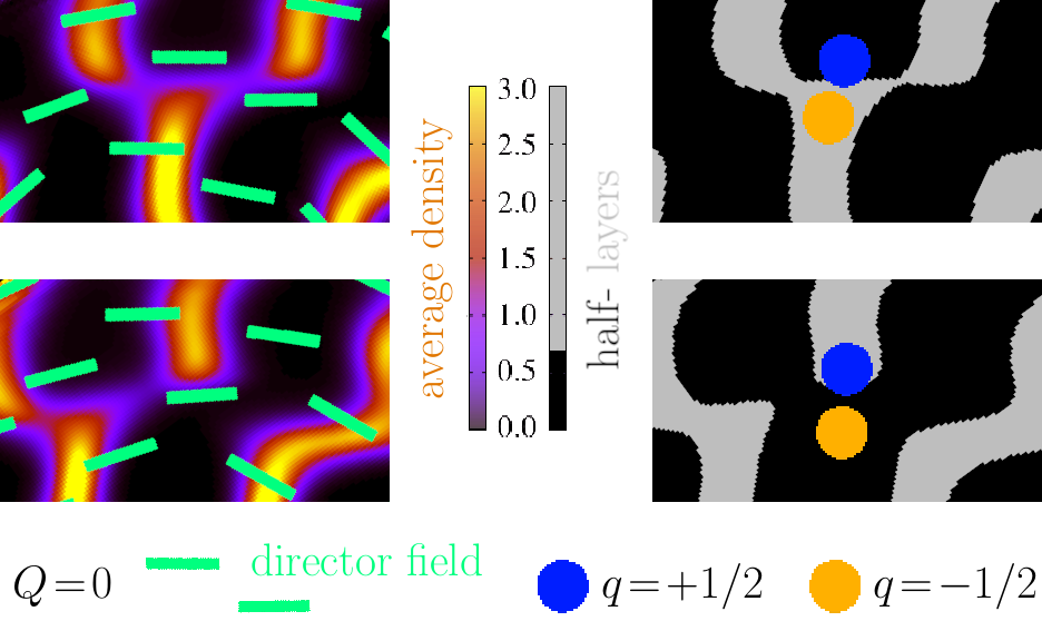
To provide a typical example for the identification of topological charges and point out one particular advantage of layer topology, let us first discuss the stability of edge dislocations from a topological point of view, see Fig. 1. An edge dislocation is a spatial distortion of the layer structure, which does not involve a distortion of the orientational order (contrasting a dislocation from a disclination). In other words, there is no topological charge associated with an edge dislocation from the point of view of director topology (left panels of Fig. 1).
However, we can identify topological charges in the dual layer network (right panels of Fig. 1): layers branch out, which is associated with a negative defect and implies that one half layer must terminate at this junction, forming the associated positive defect (top row in Fig. 1). Vice versa, if a layer terminates on a defect, the opposite defect sits on the branching half layer (bottom row in Fig. 1). These observations lead to the crucial physical interpretation that edge dislocations are topologically stable composite units because oppositely charged defects sit on different networks and may thus not annihilate Aharoni et al. (2017); Machon et al. (2019), despite the zero net charge. It is further possible to determine the number of edge dislocations in a confined system by counting the interior network charges Jull et al. (2023). In contrast, the charge measured by means of director topology vanishes as the director field is uniform around the dislocation (left panels of Fig. 1), which is certainly consistent, but does not provide any additional insight.
Grain boundaries.
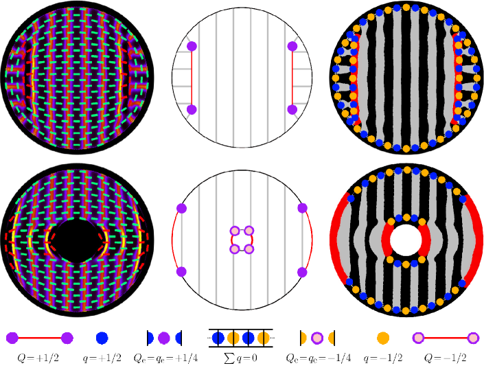
Now we turn to smectic grain boundaries forming, in extremely confined systems Monderkamp et al. (2021). To demonstrate the basic topological concepts we consider in Fig. 2 two characteristic structures classified in Ref. Wittmann et al. (2021): a bridge state with two interior grain boundaries in circular confinement (top row) and a laminar state with only virtual grain boundaries in annular confinement (bottom row). As no other singular objects are present, the total charge ( for the disk and for the annulus) must be distributed over the grain boundaries.
Director topology.
Regarding the director field, shown as green stripes in the left panels of Fig. 2, the topology of the grain boundaries can be directly determined from following appropriate contours, encircling the whole region with discontinuous orientations (highlighted in the director field by using a red color instead of green). In addition, the virtual defects at the confining walls are identified by the deviation from the preferred alignment of the hard rods parallel to the confining walls. Thus, they can be treated analogously to interior defects by a virtual extension of the director field satisfying this presumed anchoring condition Monderkamp et al. (2021); Wittmann et al. (2021) (in fact, using density functional theory, the virtual defects are directly visible in the director field, as there is always a small probability for each allowed orientation). As illustrated in the central panels of Fig. 2, the two grain boundaries in the bridge state as well as the virtual ones at the outer walls in the laminar state carry a charge of each, while those close to the inclusion in the laminar state have . Analyzing the director field upon assuming tetratic symmetry, such that a perpendicular orientation of two rods does not represent a defect, reveals a fine structure with charges and at the endpoints of these positively and negatively charged grain boundaries, respectively. We demonstrate below that this established picture is consistent with the conclusions that can be drawn from layer topology and present additional insight from the synergy of these two different points of view.
Layer topology.
In the right panels of Fig. 2, we show how to identify the topological charges of the grain boundaries in our two confined systems using layer topology, recalling that charge conservation requires a boundary rule (in analogy to the presumed parallel director alignment) at the confining walls. To this end, the boundary must be identified with one network Monderkamp et al. (2023), i.e., the network of layers, or as done here, the network of half layers (which intuitively indicate the absence of particles both between the layers and beyond the confining walls). Doing so, we obtain a sequence of equidistant alternating charges, which average out throughout defect-free confining walls, as illustrated in the legend of Fig. 2. As for an edge dislocation, the fact that does not necessarily imply that oppositely charged defects can annihilate, since they are associated with different networks.
To analyze the distribution of layer defects over a grain boundary, let us first take a closer look at the bridge state in the top row of Fig. 2. As for director topology (left panel), the alternating charges at the confining walls indicate that the total charge must be distributed in the interior of the system, i.e., at the two grain boundaries. Here, these grain boundaries are recognized as the locus of the interior defects in the two networks of layers and half-layers (right panel). Further inspection again reveals a sequence of alternating charges, which ends here at each side of each grain boundary on a positive defect associated with a terminating layer. Upon averaging over the defect pairs along the grain boundary, as illustrated in the legend of Fig. 2, we recognize that each endpoint defect has one oppositely charged neighbor, which only compensates half of its charge. The remaining half suggests the interpretation of a point defect with located at the end of the grain boundary. This leaves the overall picture of a positively charged grain boundary with two quarter charges at the endpoints (central panel), which is consistent with the charge distribution identified using director topology.
While director topology arguably provides a physically more intuitive picture of the topological fine structure of a grain boundary in terms of coexisting symmetries, the analogous definition in layer topology directly extends to virtual grain boundaries, i.e., it is straightforward to identify and visualize quarter-charged boundary defects, which are not visible in local order parameter fields Monderkamp et al. (2021). To illustrate this procedure, we consider next the laminar structure in the bottom row of Fig. 2, which only possesses one large domain of nearly parallel layers and a practically uniform director field throughout the interior region (left panel). In this circumstance, a virtual grain boundary can be identified, using layer topology, by the absence of a regular alternating pattern of oppositely charged defects at the confining walls (right panel). With this gap, the charges do not average out along the confining walls, such that there is a positive defect , associated with the terminating outermost layers, and a negative defect , associated with branching half-layers, at each end of each virtual grain boundary at the outer and inner walls, respectively. Again, averaging over direct neighbors results in corresponding positive and negative quarter charges at the endpoints (central panel). While this is also consistent with director topology, the present layer topological approach enables a direct visualization of these virtual endpoint defects.
In summary, the main difference to director topology, where the charge of a grain boundary of any kind follows from considering a closed contour encircling the whole defect, is that an the appearance of interior/virtual grain boundaries in layer topology is different, as it must be identified from the presence/absence of a sequence of alternating oppositely charged defects. The quarter charge of the endpoints, on the other hand, directly follows from the exceptional role of the outermost defects in such a sequence, which have only one neighbor.
Conclusions.
To conclude, both layer topology and director topology can be used to identify the topological charge and the fine structure of interior and virtual smectic grain boundaries. While these two concepts are not strictly dual to each other, the most comprehensive picture can be obtained by employing them in synergy. (i) The discontinuous order throughout a grain boundary becomes apparent in both the director field and the layer networks. (ii) The total topological charge of a grain boundary follows when taking into account the full spatial extent, upon observing (iia) the distribution of alternating charges on the dual layer network or (iib) the elongated structure of the nematic defect; (iii) a fine structure involving quarter charges can be (iiia) found in layer topology by heuristically splitting and eliminating oppositely charged neighboring network defects and (iiib) substantiated in director topology by identifying point defects in the tetratic field; (iv) the fine structure of virtual defects, which are located at the confining walls or outside the system, (iva) follows from layer topology in full analogy to interior defects, such that this direct observation justifies (ivb) the indirect classification of such defects using director topology, as it is not possible to measure local order parameter fields outside the system.
In view of practical applications, the layer networks and their defects can be automatically identified and analyzed in both colloidal experiments and simulations of hard rods Monderkamp et al. (2023); Jull et al. (2023). Moreover, layer topology can be applied to grain boundaries at which the terminating layers are not perpendicular and to systems in which different physical anchoring conditions are imposed. This suggests advantages over director topology when targeting applications for molecular liquid crystals Michel et al. (2004, 2006); Coursault et al. (2016); Zappone et al. (2020); Zappone and Lacaze (2022) and related continuum models Ball et al. (2023).
Acknowledgements.
The idea for this article originated from conversations with Emmanuelle Lacaze, following stimulating discussions with her and Daniel Beller at the 16th European Conference on Liquid Crystals. I am thankful to Randall Kamien for providing valuable insight into layer topology at the Banff International Research Station (Workshop 22w5159). I also thank Paul A. Monderkamp and Hartmut Löwen for a critical reading of the manuscript and helpful suggestions. Financial support by the Deutsche Forschungsgemeinschaft (DFG) through the SPP 2265, under Grant No. WI 5527/1-1, is gratefully acknowledged.
References
- Zappone and Lacaze (2022) B. Zappone and E. Lacaze, Liq. Cryst. Rev. pp. 1–18 (2022).
- Wittmann et al. (2023) R. Wittmann, P. A. Monderkamp, J. Xia, L. B. Cortes, I. Grobas, P. E. Farrell, D. G. Aarts, and H. Löwen, Phys. Rev. Research 5, 033135 (2023).
- O’Keefe et al. (2023) M. O’Keefe, J. B. D. M. Garcia, A. J. Rwakabuba, T. M. Otchy, D. A. Beller, and M. A. Gharbi, arXiv preprint arXiv:2306.01118 (2023).
- Jeridi et al. (2022) H. Jeridi, J. de Dieu Niyonzima, C. Sakr, A. Missaoui, S. Shahini, A. Vlad, A. Coati, N. Goubet, S. Royer, I. Vickridge, et al., Soft Matter 18, 4792 (2022).
- Monderkamp et al. (2021) P. A. Monderkamp, R. Wittmann, L. B. G. Cortes, D. G. A. L. Aarts, F. Smallenburg, and H. Löwen, Phys. Rev. Lett. 127, 198001 (2021).
- Wittmann et al. (2021) R. Wittmann, L. B. G. Cortes, H. Löwen, and D. G. A. L. Aarts, Nat. Commun. 12, 623 (2021).
- Monderkamp et al. (2022) P. A. Monderkamp, R. Wittmann, M. te Vrugt, A. Voigt, R. Wittkowski, and H. Löwen, PCCP 24, 15691 (2022).
- Xia et al. (2021) J. Xia, S. MacLachlan, T. J. Atherton, and P. E. Farrell, Phys. Rev. Lett. 126, 177801 (2021).
- Paget et al. (2022) J. Paget, U. Alberti, M. G. Mazza., A. J. Archer, and T. N. Shendruk, J. Phys. A: Math. Theor. 55, 354001 (2022).
- Paget et al. (2023) J. Paget, M. G. Mazza, A. J. Archer, and T. N. Shendruk, Nat. Commun. 14, 1048 (2023).
- Cortes et al. (2017) L. B. G. Cortes, Y. Gao, R. P. A. Dullens, and D. G. A. L. Aarts, J. Phys. Condens. Matter 29, 064003 (2017).
- Jull et al. (2023) E. I. L. Jull, G. Campos-Villalobos, Q. Tang, M. Dijkstra, and L. Tran, arXiv preprint arXiv:2311.18362 (2023).
- Michel et al. (2004) J.-P. Michel, E. Lacaze, M. Alba, M. De Boissieu, M. Gailhanou, and M. Goldmann, Phys. Rev. E 70, 011709 (2004).
- Michel et al. (2006) J.-P. Michel, E. Lacaze, M. Goldmann, M. Gailhanou, M. De Boissieu, and M. Alba, Phys. Rev. Lett. 96, 027803 (2006).
- Coursault et al. (2016) D. Coursault, B. Zappone, A. Coati, A. Boulaoued, L. Pelliser, D. Limagne, N. Boudet, B. H. Ibrahim, A. De Martino, M. Alba, et al., Soft Matter 12, 678 (2016).
- Zappone et al. (2020) B. Zappone, A. E. Mamuk, I. Gryn, V. Arima, A. Zizzari, R. Bartolino, E. Lacaze, and R. Petschek, Proc. Natl. Acad. Sci. U.S.A. 117, 17643 (2020).
- Poénaru (1981) V. Poénaru, Commun. Math. Phys. 80, 127 (1981).
- Kurik and Lavrentovich (1988) M. V. Kurik and O. Lavrentovich, Phys.-Uspekhi 31, 196 (1988).
- Chen et al. (2009) B. G.-g. Chen, G. P. Alexander, and R. D. Kamien, Proc. Natl. Acad. Sci. U.S.A. 106, 15577 (2009).
- Kamien and Mosna (2016) R. D. Kamien and R. A. Mosna, New J. Phys. 18, 053012 (2016).
- Aharoni et al. (2017) H. Aharoni, T. Machon, and R. D. Kamien, Phys. Rev. Lett. 118, 257801 (2017).
- Machon et al. (2019) T. Machon, H. Aharoni, Y. Hu, and R. D. Kamien, Commun. Math. Phys. 372, 525 (2019).
- Alexander et al. (2012) G. P. Alexander, B. G.-g. Chen, E. A. Matsumoto, and R. D. Kamien, Rev. Mod. Phys. 84, 497 (2012).
- Evans (1979) R. Evans, Adv. Phys. 28, 143 (1979).
- Wittmann et al. (2017) R. Wittmann, C. E. Sitta, F. Smallenburg, and H. Löwen, J. Chem. Phys. 147 (2017).
- Monderkamp et al. (2023) P. A. Monderkamp, R. S. Windisch, R. Wittmann, and H. Löwen, J. Chem. Phys. 158 (2023).
- Ball et al. (2023) J. M. Ball, G. Canevari, and B. Stroffolini, Liq. Cryst. pp. 1–10 (2023).