Leaky Waveguide Antennas for Downlink Wideband THz Communications
Abstract
THz communications are expected to play a profound role in future wireless systems. The current trend of the extremely massive multiple-input multiple-output (MIMO) antenna architectures tends to be costly and power inefficient when implementing wideband THz communications. An emerging THz antenna technology is leaky wave antenna (LWA), which can realize frequency selective beamforming with a single radiating element. In this work, we explore the usage of LWAs technology for wideband multi-user THz communications. We propose a model for the LWA signal processing that is physically compliant facilitating studying LWA-aided communication systems. Focusing on downlink systems, we propose an alternating optimization algorithm for jointly optimizing the LWA configuration along with the signal spectral power allocation to maximize the sum-rate performance. Our numerical results show that a single LWA can generate diverse beampatterns at THz exhibiting performance comparable to costly fully digital MIMO arrays.
Index Terms— Leaky wave antennas, THz communications, power allocation, alternating optimization.
1 Introduction
Wireless communications are subject to constantly growing demands in throughput, connectivity, and latency [1]. To meet these requirements, future wireless systems are expected to utilize high-frequency regimes to overcome the spectral congestion of traditional bands [2, 3]. Particularly, the THz bands are highly attractive due to their abundant bandwidth [4].
Despite the promising spectral resources of THz bands, designing communication systems in the respective high frequencies is challenging in terms of hardware, power, and energy efficiency. THz systems are thus likely to deviate from conventional MIMO antenna architectures employed in, e.g., traditional sub-6 GHz bands [5]. To date, several different architectures are considered in the literature for THz systems. A common approach assumes hybrid analog/digital MIMO transceivers [6, 7]. However, these architectures typically rely on phase shifters [8], which can be limiting factors in terms of power consumption and frequency dependence in THz bands. A related approach implements antennas using metasurfaces [9], possibly as a form of holographic MIMO [10], though such architectures are typically not designed for wideband THz signaling up to date, and have been only conceptually studied for the narrowband case [11].
An alternative emerging antenna technology that is particularly suitable for THz communications is based on leaky waveguides [12, 13]. \Acplwa are designed to exploit the THz rainbow effect to enable frequency selective beamsteering of extremely wideband signals [14]. Accordingly, LWAs can realize different beampatterns using a single antenna element in a cost and power effective manner [15]. Despite their potential for THz systems, LWAs are mostly studied in terms of physical and propagation properties, while their signal processing model and ability to support multi-user communications have not yet been studied.
In this work, we consider LWA-aided THz communications focusing on multi-user downlink systems. We propose a physically compliant model for LWA signaling that enables exploring their beamforming capabilities for multi-user communications. We identify two design parameters of LWAs, the plate separation and slit length which can be mechanically tuned, as key controllable parameters enabling the generation of directed beams. We then propose an algorithm based on alternating optimization for jointly tuning these LWA parameters alongside the digital power allocation for wideband signaling in order to maximize the achievable sum-rate, under physical constraints. We numerically show that a single LWA can achieve various beampatterns that support multiple downlink users, achieving sum-rates that are comparable with fully digital MIMO systems using much less power.
2 System Model
2.1 Leaky Wave Antenna Model
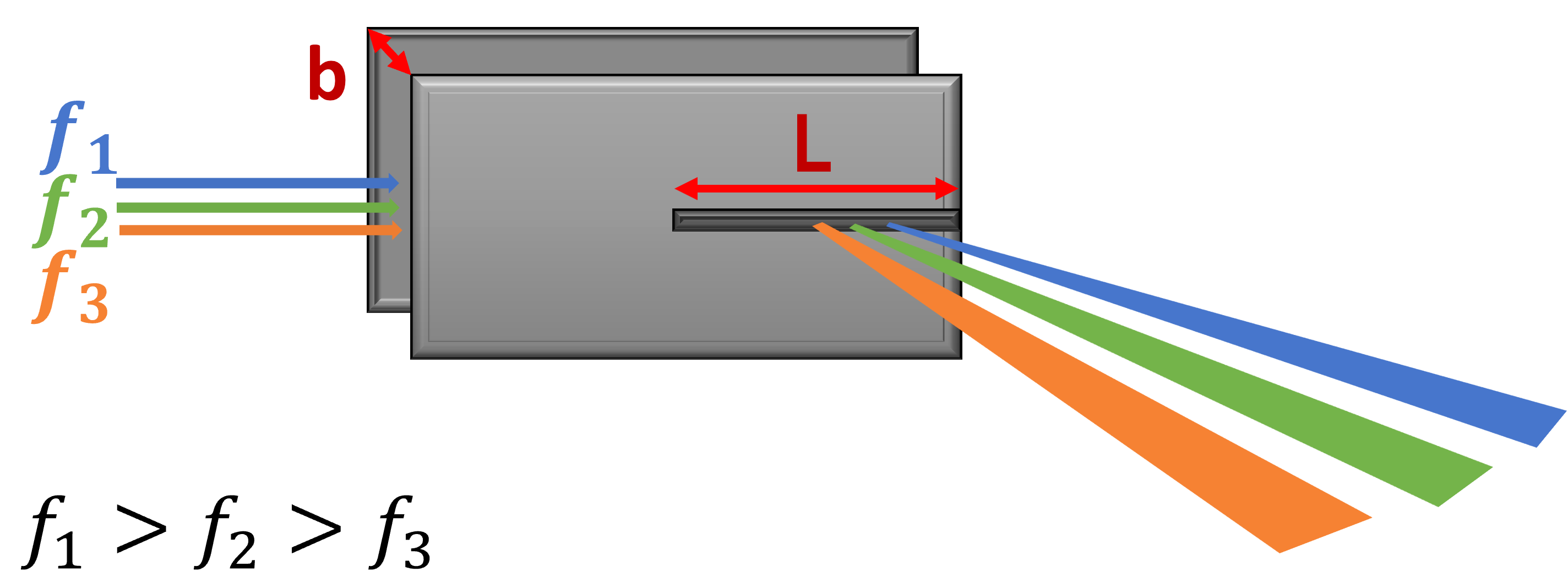
A LWA is comprised of two parallel metal plates separated by a distance . One of the plates has a slit of length , as illustrated in Fig. 1. Alternatively, one can use typical complementary metal-oxide semiconductor (CMOS) technology to fabricate LWAs [16]. As a wideband THz signal travels between the plates, it emerges from the slit in various Angle of Departures [15]. The emission angle alters monotonically for different frequency components, thus creating a THz rainbow at the LWA output. The propagation of the signal along the -length slit radiates spectral components in directed beams, in a manner that bears some similarity to synthetic apertures generated by moving devices [17]. In particular, a spectral component at frequency is radiated at azimuthal angle [15] as follows:
| (1) |
where is the speed of light. As grows inversely to , higher frequencies are emitted at lower angles relative to the plate’s axis. Each directed monochromatic beam’s angular width around its maximum emission angle depends on the LWA parameters and , and the frequency . Specifically, the diffraction pattern at angle and frequency is [15]:
| (2) |
where , is the free-space wave vector, and describes the energy loss of the transmitted wave as a result of leakage out of the slit (which is typically negligible, i.e., , thus, we use ). From (2), a single LWAs can steer THz beams by tuning and .
2.2 Problem Formulation
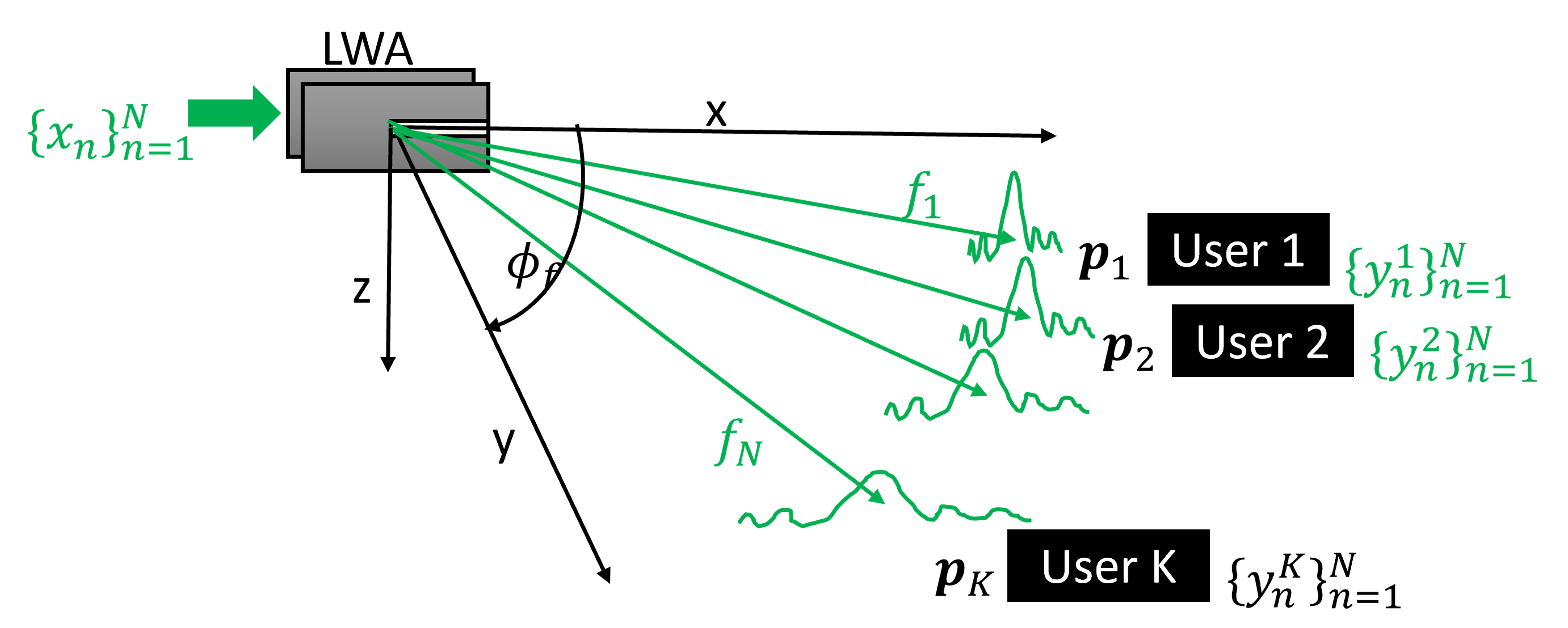
LWA-Aided Donwlink Communications: We consider a multi-user downlink setup where a base station (BS), equipped with a single LWA, serves single-antenna users. We consider only azimuthal steering in our LWA modeling, hence, we assume all users are located at the same height. We focus on line-of-sight (LOS) settings, being the expected operating regime of THz systems [18], where the th user is located at relative distance and angle from the BS. The BS employs wideband signaling with subbands at frequencies . The signal modulated at the th subband is denoted by with power , and the BS is subject to a total power constraint , i.e., it holds:
| (3) |
The usage of a LWA implies that the spectral component at frequency is emitted at angles , as depicted in Fig. 2. For simplicity, we assume each subband is sufficiently narrow such that (1) and (2) hold for the entire subband.
We let be the signal received by the th user at the th subband, and model the channel input-output relationship as follows:
| (4) |
In (4), is an attenuation coefficient, while is spectrally and temporally i.i.d. Gaussian noise with variance . is calculated according to (2).
Sum-Rate Optimization: The configuration of the LWA, i.e., the parameters and , affects the channel input-output relationship via in (4). Accordingly, we aim to tune and along with the power allocation based on the sum-rate objective.
To formulate the objective, we define as the th subband channel vector, such that
| (5) |
Using this notation, the achievable sum-rate at frequency is given by [19]
| (6) |
Accordingly, the average achievable sum-rate of the wideband transmission is given by
| (7) |
The LWA parameters and are typically confined to some physical ranges, i.e., and , which ensure a certain level of antenna efficiency. The resulting problem of jointly tuning the LWA and the wideband power allocation is thus expressed as follows:
| (8) | ||||
3 LWA-Aided Downlink Beamforming
3.1 Alternating Optimization
We hereinafter propose a LWA beamforming algorithm which tackles (8). We note that (8) is non-convex due to the complex dependence on and . However, if we fix and and optimize the sum-rate with respect only to , it specializes to a convex spectral power allocation problem. Therefore, our proposed algorithm alternates between two steps: Optimizing the LWA configuration and for fixed , and setting the power allocation for a fixed LWA and . We next elaborate on each of these steps, with the overall procedure summarized in Algorithm 1.
LWA Configuration: As the sum-rate objective is non-convex in and , and since both optimization variables are scalars taking value in some bounded range, we tune and for fixed using a grid search. Specifically, we divide the ranges and into uniformly spaced grids, denoted by and , respectively. At the th iteration, we scan all possible combinations on the grid to set
| (9) |
Power Allocation: For a fixed LWA configuration, maximizing the sum-rate with respect to becomes conventional spectral power allocation, which is solved via waterfilling [20, Ch. 5.3]. Accordingly, once and are fixed, we set the powers at each th iteration as follows::
| (10) |
where is set such that .
3.2 Discussion
Our proposed physically compliant modeling of LWA-based wireless communications facilitates unveiling the potential of this antenna technology for future wireless systems. From a hardware perspective, LWA technology has notable gains in cost and power due to its ability to steer wideband THz beams in a controllable manner with a single element, avoiding the usage of numerous wideband RF chains and analog combiners (that become extremely costly in THz) employed by conventional massive MIMO architectures. Our proposed alternating optimization algorithm provides a means to tune LWAs to achieve desirable beampatterns that support multiple users, as we numerically show in Section 4.
The LWA communication model in (4) is formulated for a generic path loss . Thus, while we, for simplicity, set it to be range dependent, one can also use frequency dependent profiles, which are expected to be encountered in THz. While our beampattern design is based on the sum-rate maximization formulated in (8), one can consider alternative relevant problems that follow from the LWA model. For instance, (8) is formulated assuming that the users can process the full wideband signals, while users may operate at a given subband. Moreover, in practice, the LWA configuration and is controlled via mechanical measures, and thus, one may be constrained in how frequently it can be modified. Finally, our formulation assumes that the users’ locations are known, without exploring how they are recovered by LWA-aided BSs. These extensions are left for future work.
4 Numerical Study
In this section, we numerically evaluate the ability of LWA-aided BSs in supporting multiple downlink users via our proposed beamforming design111The source code and hyperparameters used in this experimental study is available at https://github.com/yeelagn/LWA_communications.git.. We first illustrate the beampatterns achieved using a single LWA, after which we compare the resulting sum-rates to those achievable using (extremely costly) fully digital wideband THz MIMO signalling.
4.1 LWA Beampatterns
To evaluate the ability of LWA-aided BSs in generating directional beams, we consider the channel model detailed in Section 2 in the frequency range of GHz divided into frequency bins. We randomize users with relative angles and distances drawn uniformly in the ranges and meters, respectively. For each setting, we use Algorithm 1 to tune the LWA configuration in mm and mm, along the power allocation, where we use . The noise level is set to unity.
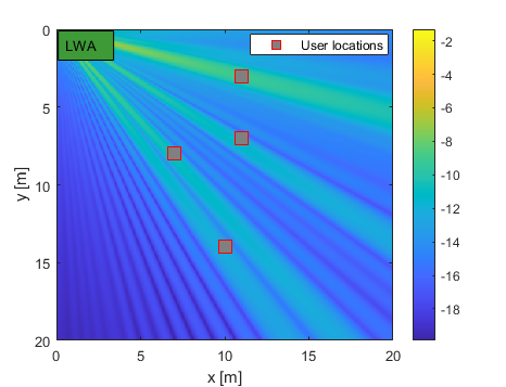
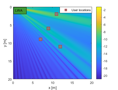
In Fig. 3, we illustrate two different beampatterns, i.e., the energy radiated towards each position , over the entire spectrum, computed as using Algorithm 1. For simplicity, we set the attenuation coefficient to scale as . We observe in Fig. 3 that a single LWA can generate relatively directed beams. Specifically, as the AoD changes monotonically with the frequency by (1), users located at small angles with respect to the LWA axis communicate at higher frequencies (with transmission power spread over multiple bins), unlike those located at larger angles. Accordingly, for users of similar distance from the LWA, Algorithm 1 is prone to assign more resources to steering beams towards the users with smaller angles. This can result in a relatively balanced serving of multiple users, as in Fig. 3(a), or alternatively, steering most of the signal power towards users at lower angles, as in Fig. 3(b). These beampatterns show the ability of LWAs to generate directed beams, and also indicate that in settings where it is crucial to guarantee balanced serving of multiple users, alternative objectives, e.g., minimal rate, should be considered.
4.2 Sum-Rate Comparison
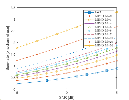
We proceed to evaluate the achievable sum-rate and compare it to that achieved with a fully digital MIMO array. We consider the same wideband setting as in Subsection 4.1 with users, and compute the sum-rate in bit-per-channel-use averaged over Monte Carlo simulations. We compare the LWA with a fully digital wideband MIMO BS equipped with a uniform linear array with half-wavelength spaced elements centered at the origin, corresponding to the antenna position in the LWA-based channel. The sum-rate is computed using spatial-spectral waterfilling [21].
Since the channel model is tightly related to the antenna architecture, for the MIMO setting, we obtain the channel using the LOS model of [22] encompassing both radiative near- and far-field users. To guarantee a fair comparison, we normalize the MIMO channels to have the same max tap magnitude as the LWA channel, and compute the sum-rate versus the average signal-to-noise ratio (SNR) defined as . We only normalize the MIMO channels to ensure that the optimization algorithm suggested in Subection 3.1 offers a solution independent of the channel normalization. The results, reported in Fig. 4, show that the optimal sum-rate achieved by a LWA-based channel is comparable to the sum-rates achieved by the MIMO setting, and may offer a valuable alternative to the (costly and currently non-feasible) traditional setting, while supporting wideband transmissions.
5 Conclusion
In this paper, we studied wideband THz downlink multi-user communications using LWAs. We introduced a physically compliant model for LWA-aided communications that encapsulates the ability of LWAs in generating frequency-selective directed THz beams with a single element. We proposed an alternating optimization method for jointly tuning the LWA configuration alongside the spectral power allocation. Our numerical results show that a single LWA can generate directed beams towards multiple users, and achieve sum-rates comparable to (extremely costly) fully digital MIMO array.
References
- [1] M. Giordani, M. Polese, M. Mezzavilla, S. Rangan, and M. Zorzi, “Toward 6G networks: Use cases and technologies,” IEEE Commun. Mag., vol. 58, no. 3, pp. 55–61, 2020.
- [2] W. Saad, M. Bennis, and M. Chen, “A vision of 6G wireless systems: Applications, trends, technologies, and open research problems,” IEEE Netw., vol. 34, no. 3, pp. 134–142, 2019.
- [3] T. S. Rappaport, Y. Xing, O. Kanhere, S. Ju, A. Madanayake, S. Mandal, A. Alkhateeb, and G. C. Trichopoulos, “Wireless communications and applications above 100 GHz: Opportunities and challenges for 6G and beyond,” IEEE Access, vol. 7, pp. 78 729–78 757, 2019.
- [4] C.-X. Wang, J. Wang, S. Hu, Z. H. Jiang, J. Tao, and F. Yan, “Key technologies in 6G terahertz wireless communication systems: A survey,” IEEE Veh. Technol. Mag., vol. 16, no. 4, pp. 27–37, 2021.
- [5] M. Polese, J. M. Jornet, T. Melodia, and M. Zorzi, “Toward end-to-end, full-stack 6G terahertz networks,” IEEE Commun. Mag., vol. 58, no. 11, pp. 48–54, 2020.
- [6] N. Thanh Nguyen, M. Ma, N. Shlezinger, Y. C. Eldar, A. Swindlehurst, and M. Juntti, “Deep unfolding hybrid beamforming designs for THz massive MIMO systems,” arXiv preprint arXiv:2302.12041, 2023.
- [7] I. E. Berman and T. Routtenberg, “Resource allocation and dithering of Bayesian parameter estimation using mixed-resolution data,” IEEE Trans. Signal Process., vol. 69, pp. 6148–6164, 2021.
- [8] S. S. Ioushua and Y. C. Eldar, “A family of hybrid analog–digital beamforming methods for massive MIMO systems,” IEEE Trans. Signal Process., vol. 67, no. 12, pp. 3243–3257, 2019.
- [9] N. Shlezinger, G. C. Alexandropoulos, M. F. Imani, Y. C. Eldar, and D. R. Smith, “Dynamic metasurface antennas for 6G extreme massive MIMO communications,” IEEE Wireless Commun., vol. 28, no. 2, pp. 106–113, 2021.
- [10] C. Huang, S. Hu, G. C. Alexandropoulos, A. Zappone, C. Yuen, R. Zhang, M. Di Renzo, and M. Debbah, “Holographic MIMO surfaces for 6G wireless networks: Opportunities, challenges, and trends,” IEEE Commun. Mag., vol. 27, no. 5, pp. 118–125, 2020.
- [11] I. Gavras, M. A. Islam, B. Smida, and G. C. Alexandropoulos, “Full duplex holographic MIMO for near-field integrated sensing and communications,” arXiv preprint arXiv:2303.07792, 2023.
- [12] H. Guerboukha, R. Shrestha, J. Neronha, Z. Fang, and D. M. Mittleman, “Conformal leaky-wave antennas for wireless terahertz communications,” Communications Engineering, vol. 2, no. 1, p. 17, 2023.
- [13] O. Zetterstrom, E. Pucci, P. Padilla, L. Wang, and O. Quevedo-Teruel, “Low-dispersive leaky-wave antennas for mmWave point-to-point high-throughput communications,” IEEE Trans. Antennas Propag., vol. 68, no. 3, pp. 1322–1331, 2019.
- [14] Y. Ghasempour, C.-Y. Yeh, R. Shrestha, Y. Amarasinghe, D. Mittleman, and E. W. Knightly, “LeakyTrack: Non-coherent single-antenna nodal and environmental mobility tracking with a leaky-wave antenna,” in Conference on Embedded Networked Sensor Systems (SenSys), 2020.
- [15] Y. Ghasempour, R. Shrestha, A. Charous, E. Knightly, and D. M. Mittleman, “Single-shot link discovery for terahertz wireless networks,” Nature communications, vol. 11, no. 1, p. 2017, 2020.
- [16] H. Saeidi, S. Venkatesh, X. Lu, and K. Sengupta, “22.1 THz Prism: One-shot simultaneous multi-node angular localization using spectrum-to-space mapping with 360-to-400GHz broadband transceiver and dual-port integrated leaky-wave antennas,” in IEEE International Solid- State Circuits Conference (ISSCC), vol. 64, 2021, pp. 314–316.
- [17] A. Moreira, P. Prats-Iraola, M. Younis, G. Krieger, I. Hajnsek, and K. P. Papathanassiou, “A tutorial on synthetic aperture radar,” IEEE Geosci. Remote Sens. Mag., vol. 1, no. 1, pp. 6–43, 2013.
- [18] C. Han, Y. Wang, Y. Li, Y. Chen, N. A. Abbasi, T. Kürner, and A. F. Molisch, “Terahertz wireless channels: A holistic survey on measurement, modeling, and analysis,” IEEE Commun. Surveys Tuts., vol. 24, no. 3, pp. 1670–1707, 2022.
- [19] Z. Shen, R. Chen, J. G. Andrews, R. W. Heath, and B. L. Evans, “Sum capacity of multiuser MIMO broadcast channels with block diagonalization,” IEEE Trans. Wireless Commun., vol. 6, no. 6, pp. 2040–2045, 2007.
- [20] D. Tse and V. Pramod, Fundamentals of wireless communication. Cambridge University Press, 2005.
- [21] L. Brandenburg and A. Wyner, “Capacity of the Gaussian channel with memory: The multivariate case,” Bell System Technical Journal, vol. 53, no. 5, pp. 745–778, 1974.
- [22] H. Zhang, N. Shlezinger, F. Guidi, D. Dardari, M. F. Imani, and Y. C. Eldar, “Beam focusing for near-field multiuser MIMO communications,” IEEE Trans. Wireless Commun., vol. 21, no. 9, pp. 7476–7490, 2022.