Design and Control of an Energy Accumulative Hopping Robot
Abstract
Jumping and hopping locomotion are efficient means of traversing unstructured rugged terrain with the former being the focus of roboticists. This focus has led to significant performance and understanding in jumping robots but with limited practical applications as they require significant time between jumps to store energy, thus relegating jumping to a secondary role in locomotion. Hopping locomotion, however, can preserve and transfer energy to subsequent hops without long energy storage periods. Therefore, hopping has the potential to be far more energy efficient and agile than jumping. However, to date, only a single untethered hopping robot exists with limited payload and hopping heights ( 1 meter). This is due to the added design and control complexity inherent in the requirements to input energy during dynamic locomotion and control the orientation of the system throughout the hopping cycle, resulting in low energy input and control torques; a redevelopment from basic principles is necessary to advance the capabilities of hopping robots. Here we report hopping robot design principles for efficient and robust systems with high energy input and control torques that are validated through analytical, simulation, and experimental results. The resulting robot (MultiMo-MHR) can hop nearly 4 meters ( 6 times the current state-of-the-art); and is only limited by the impact mechanics and not energy input. The results also directly contradict a recent work that concluded hopping with aerodynamic energy input would be less efficient than flight for hops greater than 0.4 meters.
Index Terms:
Hopping, Robot, Control, Energy Accumulation, EfficiencyI Introduction
Jumping robots have been under significant development for decades demonstrating a diversity of designs, energy storage and release mechanisms, and additional behaviors such as gliding and self righting [1, 2]. Jumping locomotion tends to produce the highest specific energy (energy/mass) systems [3, 4], as compared to hopping because they do not require the additional components necessary for hopping locomotion; namely those for orientation control. This has led to impressive, high specific energy, jumping robot designs with added features demonstrating minimalist high performance jumping [3, 5, 6], micro jumping robots [7, 8, 9, 10, 11], linkage based leg designs [12, 13, 14, 15], linear leg designs [16, 17, 18, 19], buckling leg designs [20, 21, 22], spring leg design [3], self-righting [23, 24, 25, 26], steering [27, 13], aerial orientation control [28], surface adaptation [29], gliding [30, 31, 32, 33, 34, 35, 36], flight [37], legged [38, 39, 40, 41], wheeled [15, 42, 43], and soft jumpers [44, 45]. However, jumping systems tend to recover no energy from previous jumps and therefore have limited efficiency, performance, and agility. A basic performance metric for vertical jumping height, , is highly coupled to mass. To produce the highest performance jumping systems the energy storage part of the cycle can take tens of seconds, drastically limiting the robot’s agility. Hopping robots, or robots that repetitively jump, provide a path forward as they are more efficient, recovering energy from previous hops, and are more agile, as they do not require long delays between hops to store energy, locomote, reposition, or stabilize; the initiation of hops is determined by the fundamental dynamic behavior as opposed to arbitrarily by the controller.
Researchers have been studying hopping robots since they were first developed by Raibert et al. in 1984 [46, 47], however, due to their design and control complexity from the necessity to maintain orientation and input energy over the extremely short time periods between successive hops and complex ground interactions, four decades later and only an extremely small number have ever been developed with limited payload, performance, and most being tethered [48, 49, 50, 46, 47, 51, 52]. While hopping locomotion has been studied most notably in Salto, these robots do not change their locomotion energy (LE = sum of the desired kinetic, gravitational potential, and elastic potential energies) over successive hops, they maintain a nearly constant level [50]. In addition, these robots do not have sufficient performance to support a payload of task specific components; with Salto’s average hopping height of 0.65 m at 100 grams a 10 gram payload would significantly reduce the system’s performance. Given that we expect systems with energy input and loss to stabilize over time, we seek to understand whether LE can not only be accumulated (increased) but done so through constant actuator power output. Nature however provides an answer. Observations of desert kangaroo rats (Dipodomys deserti) shows an extraordinary aspect of their hopping locomotion; their LE increases over successive hops. They accumulate energy with each cycle not only in their forward kinetic energy but in their elastic tissues as well, all while their metabolic rate remains constant with increasing velocity [53]; imagine running as fast as you can but feeling like you are walking. These animals incredibly store, accumulate, convert, and release energy from previous cycles to increase their LE over time without increasing their averaged actuator power. Energy accumulation in robotics has been explored in a tethered one-degree-of-freedom robot, however, the robot is only able to achieve an increase in hopping height of approximately 35 mm as the dynamic behavior surpasses the actuator’s speed [54]. An additional work presented a simulation which shows an increase in hopping height of 250 mm, however, this behavior is not shown to exist in the robot [55]. The accumulation of energy at a constant actuator power output opens the possibility to high-performance hopping, as typically high performance jumping and hopping requires proportionally larger actuators who’s mass in turn reduces performance. Realizing this concept in a robotic platform would not only eliminate the need for large actuators, but, through accumulation, allow a robot to achieve significant hopping heights.
With inspiration from Salto which utilizes propellers for orientation control, its natural to consider using propellers for both orientation control and energy input for hopping. Zhu et al. demonstrated this concept in the PogoDrone [37], however, as stated at 0.5 meters ”bouncing performs worse than simply hovering”; assuming the extra mass associated with the bouncing mechanism is removed, this system would likely always perform better in hover. This poses a quandary, as hopping and jumping are known to be efficient means of overcoming obstacles in terrestrial locomotion and typically more efficient than powered flight [56]. However, as stated, this robot is designed to periodically bounce to ”take samples of soil”, while the vast majority of time is spent in flight; experimental results show thrust is never reduce below approximately 60% of hover, indicating a slowed decent which is not applicable to an efficient hopping behavior. The conclusion of the work states that the robot may have the ”potential to efficiently operate in low heights”, but this is not explored. While this work has focused on the addition of a bouncing mechanism to a flying robot, we seek to explore the fundamental development of a high-performance hopping robot which utilizes a rotor configuration for energy input and orientation control. In particular, to understand the fundamentals of hopping locomotion, energy accumulation at constant actuator power output, efficiency, aerodynamic energy input, and control of a high-performance hopping robot.
II Energy Accumulation Concept
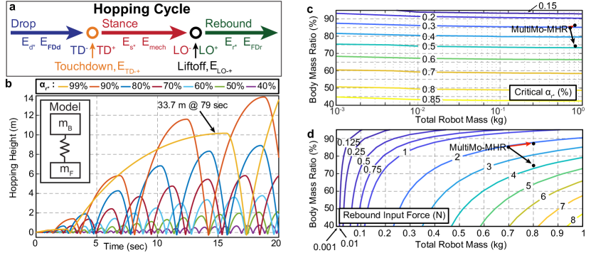
Locomotion strategies tend to require cyclic motions in which the LE is modified over the course of the cycle. In hopping locomotion, the hopping cycle can be divided into three phases, including drop, stance, and rebound, and two transitions, including touchdown (TD) and liftoff (LO); as seen in Fig. 1a. Each phase has both the potential for a control input to add or remove LE and a characteristic loss of LE, whereas, each transition has only a characteristic loss of LE; yielding eight distinct energy modifications. The energy which must be input to overcome the losses and achieve a specific hopping height ratio, , is therefore,
| (1) |
where, total mass, , drop height, , rebound height, , and gravity, , are represented accordingly. The height ratio , , and indicates increasing (LE accumulation), decreasing (LE dissipation), and constant (constant LE) hopping heights; where the latter (constant LE) has been the focus of previous hopping robots. The control input energies during the drop, , stance, , and rebound, , phases are specified by the controller. This accounts for all jumping and hopping robots as energy input can be through aerodynamic forces (e.g., propellers, thrusters) that can add LE throughout all phases (, , ) or leg forces (e.g. direct actuation, released elastic energy, combustion) that can only input LE during the stance phase (). Assuming an atmosphere, this highlights a significant benefit of aerodynamic LE inputs, in addition to their potential dual use for orientation control. Assuming an atmosphere, energy will be lost to aerodynamic drag (drop, , and rebound, ). At touchdown, assuming high contact damping, the energy in component(s) which make direct contact with the ground will be lost, leading to a touchdown loss, . The indicates the transition from the instantaneous moment prior to contact (-) to that after (+); where this simplifies the complex impact mechanics. During the stance phase the energy storage and release mechanisms move, creating loses due to friction in the mechanisms and dissipation in the elastic material, leading to a mechanical loss, . At liftoff, as energy must be transferred between components such that the entire system is moving at a constant velocity, energy may be lost in the transfer, leading to a liftoff loss, . The indicates the transition from the instantaneous moment prior to liftoff (-) to the moment after (+). The hopping cycle efficiency is therefore, , where, ’s represent the energy losses; which may include required control inputs that remove energy (e.g., stabilization).
II-A Energy Accumulation Design.
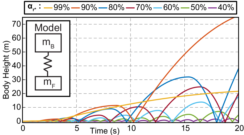
To explore the accumulation of energy, a simple model is proposed, Fig. 1b. Assuming the main spring and the ground contact are modelled as springs with dampers, the dynamics are governed by,
| (2) | |||
| (3) |
where, the vertical position, , mass, , spring constant, , and damping coefficient, , of the body and the vertical position, , mass, , spring constant, , and damping coefficient, , of the foot are represented accordingly. Figure 1b,c assumes the body input force, , is the sum of the drag force and, during the rebound, the control input force, ; the foot input force, . A conservative estimate of the drag coefficient and effective area, , is assumed constant due to the low slope of the linear fit from appendix: experimental energies. From experimental observations, the foot-ground damping is assumed to be high, while the body-foot damping is assumed negligible during spring extension. In simulation, the spring and damping value are modified to account for the current operational phase and relative position of the components and the ground.
Focusing on the addition of LE during the rebound phase, , using aerodynamic forces, the rebound control inputs will assume a constant actuator power output and thus constant aerodynamic force (thrust). However, instead of energy consumed by the actuator, we will consider work done on the robot. Therefore, the work done by the input force, , on the robot is, . Normalizing by the rebound energy, , produces the rebound control input ratio, , which is the ratio of the input force to the gravitational force; where, the robot is flying and the robot is falling. Using the parameters of the initial prototype and the determined drag and touchdown losses, Fig. 1b (equations 2, 3), shows energy can be accumulated without sufficient thrust for flight; where, even produces an accumulation of energy over multiple hopping cycles. Furthermore, as this force is only produced during the rebound phase, the force averaged over the full hopping cycle would be even less; e.g., a quadrotor would have to continuously produce a force equal to the gravitational force, however, a hopping robot producing less force, would only be required to do so over the rebound phase; this contradicts the conclusions reached by the previous work [37]. The hopping robot therefore has the potential to be substantially more efficient and yield longer operational times than those of rotorcraft robots. However, assuming spring stiffness and mass do not change, spring-mass systems have a constant natural frequency, that translates into a nearly constant ground contact time across varying hopping heights. Therefore, accumulating energy with direct leg actuation would fundamentally require an increase in actuator power output over the stance phase; while average power may remain constant as the aerial phase time would increase.
The minimum point at which a hopping robot will accumulate energy with energy input during the rebound, is the critical , Fig. 1c; where the critical input force, , is seen in Fig. 1d. Over four orders-of-magnitude in robot mass and body mass percentages from 0.4 to 0.95, Fig. 1c shows the critical is highly dependent on body mass percentage, , and nearly constant (slight negative slope) in total robot mass, . Therefore, as body mass increases the critical decreases, whereas, increases in foot mass significantly increases the critical . Assuming the actuator’s mass is proportional to its output force, this indicates that body mass increases will result in proportionally less actuator mass, whereas, foot mass increases will result in proportionally more actuator mass (i.e., more of the system’s mass will be devoted to the energy input actuators). Moreover, from Fig. 1d, the critical force, , may remain nearly constant with increases of body mass; however, this is dependent on the body mass ratio and total mass of the robot. Therefore, given an existing system and a required body mass increase, the critical force can be use to determine the required increase in actuator power output or reduction in foot mass necessary to maintain the same actuator power output. As an example, a 100 gram increase to the prototype’s (MultiMo-MHR) body mass (red arrow) results in nearly no change in the required thrust, whereas, the same increase in the foot mass (black arrow) would require nearly twice the thrust. This creates a fundamentally new design paradigm for hopping robots, as larger body masses require proportionally less input force, as a function of the mass, to accumulate energy, therefore freeing up mass for additional components and complexity.
The fundamental scaling relationship between energy modifications can be determined by normalizing the changes to the LE by the characteristic energy of the phase or transition. At the initiation of the drop phase the robot has an initial energy equal to which is modified in eight distinct ways over the course of the hopping cycle. Rewriting equation 1 leads to the the energy at the apex of the rebound phase of,
| (4) |
However, these energies are highly coupled making determination from experimental data and generalization difficult without separating the phases and transitions. During the drop, the energy can be modify by the drop control input, , and drag, , resulting in the energy just prior to touchdown of,
| (5) | |||
where, is the velocity just prior to touchdown. The robot then undergoes the touchdown transition, losing energy, , resulting in the energy at the initiation of the stance phase,
| (6) | |||
The stance phase energy can be modified by the stance control input, , and mechanical losses, , resulting in the energy just prior to liftoff of,
| (7) | |||
where, is the velocity just prior to liftoff. The robot then undergoes the second transition in which energy can be lost in the transfer between components, , resulting in the energy just after liftoff of,
| (8) |
where, is the velocity just after liftoff. The robot then enters the rebound phase in which the energy can be modified by the rebound control input, , and drag, , resulting in the energy at the apex of the hop of,
| (9) |
where, is the rebound height and the drop point for the subsequent hop. However, the velocity just after liftoff, , is difficult to measure. Therefore, to remove the velocity just after liftoff, equations 8,9 can be combined; leading to,
| (10) | |||
| (11) |
Combining these equations together yields the ratio of the rebound height to drop height, , as,
| (12) |
where, the terms representing control inputs including, , , and can be either positive or negative, indicating adding or removing energy from the system. Terms that will always be negative, thereby removing energy from the system, include, , , , , and will be replaced with indicating an effective efficiency measure (not necessarily a true efficiency). The rebound control input must be , as greater than one would indicate a average force greater than gravity, and the robot would continue to rise indefinitely. Experimental determination of these energies is discussed in appendix: experimental energies.
Solving equation 12 for the rebound energy input ratio, , yields,
| (13) |
where other jumping and hopping robots may choose to solve for the energy input ratio related to their input strategy. Considering all potential modifications to the LE, given aerodynamic based rebound energy input, increases in body mass at would result in increases to the effective efficiencies . Therefore, from equation 13 and assuming the mechanical losses, , scale with mass, increasing body mass would result in decreasing the required rebound energy input ratio, , and thus actuator size as a function of the body mass, allowing for high performance hopping robot designs with sufficient payload for task specific components.
II-B Mass Scaling.
Scaling however, is usually assumed to apply to the entire robot; i.e., as body mass increases so too would the foot mass to withstand the increased locomotion forces exerted by the body mass. This is a common misconception that stems from applying jumping robot concepts to hopping robots. Due to the touchdown in hopping robots, creating an additional spring-mass system, the maximum force experienced by the foot is typically not applied by the body during the stance phase and is instead applied by the foot at touchdown (equations 2, 3). Additionally, the natural frequency of the foot-ground interface tends to be significantly greater than that of the body-foot. Assuming high damping in the foot-ground interface, the high impact forces will be dissipated before the body can apply any significant forces. Therefore, the determining factor in required foot strength is the foot mass, foot-ground interface stiffness, and touchdown velocity. While foot mass is typically difficult to reduce and drag couples the total mass to touchdown velocity for a given height, the force is extremely sensitive to the foot-ground interface stiffness which can be easily adjusted with changes to the foot contact material; As an example, assuming a touchdown velocity of 5.9 m/s (approximately 2 meter drop) and a maximum foot compression of 0.3 mm, the model predicts, a maximum foot acceleration of 1055 g’s (1128 N) at touchdown as compared to the maximum body acceleration during stance of 23 g’s (134 N); the touchdown forces are over 8 times larger. Increasing the foot compression to 0.9 mm reduces the foot acceleration to 319 g’s (338 N). This therefore decouples the foot mass from the body mass allowing for independent scaling and design.
III Robot Design
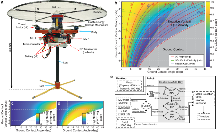
The idealized simple model provides inspiration for a maximally efficient hopping robot. It has no joints or connections to the elastic energy storage device to produce friction, assuming negligible foot mass, spring mass, drag, and spring material dissipation, the simple model would be 100% efficient. To minimize the required energy input, and maximize efficiency and performance, the hopping robot design concept is centered around the idealized model. The MultiMo-MHR (Table I), is designed with a monopedal hopping leg for strong and efficient hopping locomotion and a quadrotor configuration for energy input and control (Fig. 2a). The monopedal design produces a hopping leg with a single joint and not only minimal friction but with a significant decoupling of the friction from the locomotion forces; as the locomotion forces are predominantly parallel to the friction direction. Additionally, with the inherent simplicity of the design and primarily compressive forces on the structure, the design produces an extremely strong and robust hopping leg; the leg, with a safety factor of two, can withstand the touchdown forces at terminal velocity (12.43 m/s from 33.7 m drop) of the MultiMo-MHR.
| Parm. | Description | Value | Qty |
| Body mass | 382.82 g | 1 | |
| Foot mass | 102.48 g | 1 | |
| Battery Mass | 198.97 g | 1 | |
| Spring mass | 12.27 g | 1 | |
| 587.93 g | |||
| 108.62 g | |||
| Robot Specific energy | 23.87 |
A major loss of energy in jumping and hopping robots is in the connection between the energy input device and the main elastic energy storage device. These mechanisms tend to be complex and experience high forces, which produces significant resistance to the release of these forces. To remove this impediment to hopping locomotion and maintain high efficiency, the MultiMo-MHR is designed, as with the idealized model, with no connection between the main elastic energy storage device and the energy input device, and therefore these losses are entirely removed; while the MultiMo-MHR utilizes unconnected aerodynamic energy inputs, unconnected inertial energy inputs could be used as well. The energy storage utilizes elastomers (rubber bands) for their considerably higher specific energy (energy/mass), minimizing the spring mass (appendix: elastic specific energy). The MultiMo-MHR utilized six rubber bands, which at max system stretch has an average specific energy of 23.87 for the entire robot system; the robot is designed to carry sufficient rubber bands to absorb the impact from terminal velocity (12.43 m/s at 33.7 m drop). Finally, the leg and foot designs are developed to minimize the masses of these components, while being sufficiently strong to withstand impact at terminal velocity. These collectively represent the foot of the simple model.
III-A Impact Mechanics.
As the largest forces and torques experienced by the MultiMo-MHR are during ground contact, a two degree-of-freedom model is developed to understand the behavior when the robot contacts the ground at a slight angle to the hopping axis. This will result in a torque applied to the robot body that may alter or hinder locomotion. Assuming the robot has impacted the ground, the high frequency impact dynamics have dissipated, and damping in the spring is negligible, the robot can be modelled as a planar two degree-of-freedom system during the stance phase as,
| (14) | |||
| (15) |
where, is the total rotational inertia, is the distance along the leg axis, is the spring free length, is the rotational inertia of the body about its center-of-mass (CM), is the rotational inertia of the foot about its CM, and is the distance from foot CM to the contact point. As shown in Fig. 2b-d, small angular deviations from vertical during ground contact can lead to significant changes in the liftoff angle, required friction coefficient, and vertical, horizontal, and rotational energies; e.g., a 6 m/s vertical velocity and 10 degree deviation from vertical at ground contact would result in a liftoff angle of 45 degrees, required friction coefficient of 1, and vertical, 35%, horizontal, 44%, rotational, 4%, foot contact loss, 17%, energies. This poses a significant challenge to increasing the hopping height, and would also result from off-hopping-axis positioning of the center-of-mass. To minimize this effect, the foot is designed with four passive elastic rods to resist the torque on the robot during ground contact; expanding the range over which the robot is capable of operating. Additionally, the added stability increases overall efficiency and facilitates control as the controller need not overcome as significant a deviation from the desired behavior.
III-B Control.
Assuming the MulitMo-MHR operates as a quadrotor during the aerial phase it can be modeled as such [57, 58]. A simple linear controller is developed around the model to control the system and input energy (Fig. 2e). Two onboard IMUs (6-axis, 1000Hz, MPU6050, and 9-axis, 200 Hz, WT901) provide orientation information and a motion capture system (Vicon, Vantage v5, 100Hz) provides the translational information and the thrust is provided by four quadrotor motors (iFlight XING2 1404 4600 KV with 4030 props). The horizontal positioning PID controllers are setup as cascades, generating offset angles which are included in the roll and pitch PID controllers whereas the yaw and the vertical position PID controllers operate alone. The control is separated into three components including stabilization (roll, pitch, and yaw), horizontal position (x-axis and y-axis), and LE input (z-axis), which can be individually activated. In this way LE input (accumulation, dissipation, constant LE) is accomplished through a constant feed-forward term included in the z-axis PID controller.
IV Results and Discussion
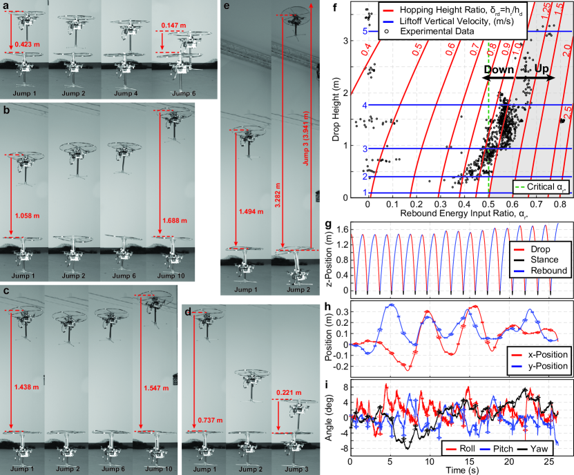
To validate the energy accumulation concept in hopping robots, experimental trials were conducted (n=805 hops). Figure 3a-e and supplementary video 1, show the MultiMo-MHR at varying drop heights and rebound control inputs specified as including unpowered, 0.5m(0%), 1.5m(0%), 2.5m(0%), 3.5m(0%), and powered, 0.5m(60%), 1m(55%), 1m(60%), 1.5m(50%), 1.5m(55%), 1.5m(65%), 1.5m(85%) and 2m(55%) trials; 10 trials were conducted of each, each with between 2-3 hops per trial for and up to 17 hops per trials at lower (Fig. 3f). The experimental procedure begins with the robot hovering at the desired drop height. The drop is initiated once stabilized, and only the stabilization controller is active. At contact, all controllers are turned off for 60 msec - approximate time of ground contact - at which point the stabilization, horizontal position, and constant energy input controllers are activated; the is a percent of the average duty cycle require to hover at the initiation of the drop. All controllers are active until the vertical velocity is reduced to less than 1 m/s, at which point only the stabilization controller remains active up to the apex of the rebound. The cycle then repeats for subsequent hops without the initial hover and stabilization part. Figure 3g-i shows that the stabilization and horizontal position controllers, in conjunction with the passive resistance of the foot to off-axis ground contacts, are capable of maintaining the robot’s position over significant time periods and hopping cycles.
IV-A Energy Accumulation.
Figure 3f shows that the MultiMo-MHR is able to accumulate energy at a critical rebound energy input ratio of or half the force of gravity; where the up arrow indicates energy accumulation and the down arrow indicates energy dissipation. Assuming the robot begins in the gray region of the plot, it will accumulate energy (increasing the rebound or subsequent drop height) until it reaches the line, whereas, if it begins in the white region, it will dissipate energy until it reaches the line or a drop height of zero; indicating cessation of hopping.
IV-B Energy Dissipation.
While the paper has focused on energy accumulation, locomotion requires the robot to both accumulate and dissipate energy. Through setting greater than the critical value and within the white region of the plot (Fig. 3f) the robot is able to dissipate energy such that it will stabilize to a lower hopping height. This feature allows for efficient control of the hopping height as the robot can simply use its inefficiencies to remove energy over time as opposed to inputting energy to change height. The maximum reduction in LE per cycle is the hopping cycle efficiency, , which can be extracted from the trials (Fig. 3f) and shows a range of between 0.35 and 0.5; which is, as expected, drop height dependent.
IV-C Locomotion Energy Modification Characteristics.
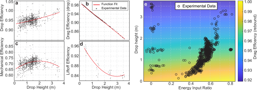
Extracting and analyzing the eight energy modifications to the LE from the experimental trials (appendix: experimental energies, Fig. 4), highlights characteristics of each. The MultiMo-MHR’s fundamental design requires that energy be removed for stabilization during the drop phase. The results show the drop energy input ratio, , reduces with increased height indicating a relatively constant reduction of energy caused by stabilization. Therefore as hopping height increases, and without perturbations, the energy reduction due to stabilization will become negligible. The mechanical efficiency, , produces relatively constant values over the tested ranges suggesting both frictional losses and dissipation in the elastic material are proportional to the LE and less dependent on the stretch length of the elastomer. The liftoff efficiency, , shows a decreasing value which may stabilize at high hopping heights suggesting, as expected, a coefficient of restitution type behavior for the impact between the body and foot. The ability to extract and analyze the individual energies allows for future generations of the MultiMo-MHR to maximize efficiency, energy accumulation, and performance. Moreover, the experimental loses suggest that only drag, which shows constant decreasing efficiency with increasing drop height, is responsible for the limit cycle behavior in which the hopping height stabilizes for a given input. As an example, assuming only touchdown losses, which is constant, energy is accumulated continuously above the critical ; verified in simulation (Fig. S1). Therefore, in non-atmospheric environments energy can be accumulated indefinitely and is only limited by the maximum specific energy of the elastic material and the strength of the robot.
V Summary
This work has redeveloped hopping robot design and energy accumulation principles from an idealized model to maximize efficiency, robustness, energy input, and performance. The design concepts that developed the MultiMo-MHR include, efficient design (limited joints, unconnected energy storage and energy input systems), robust design (linear leg, limited joints, axial forces, mass scaling), energy accumulative design (aerodynamic forces, energy input at rebound), and controls design (management of ground contact mechanics, energy input). The MultiMo-MHR is able to hop over 6 times greater than the previous state-of-the-art to heights of nearly 4 meters. This performance is not limited by the energy input, robustness, or efficiency but by the ground contact mechanics which will be the focus of future work. The experimental results also disprove the conclusion of a previous work, that hopping locomotion is only more efficient than flight at hopping heights under 0.4 meters. Finally, of the five fundamental losses in hopping locomotion only drag shows a hopping height limiting behavior, suggesting that operation in environments without an atmosphere may allow continuous energy accumulation up to the strength limits of the robot or the specific energy of the spring.
While animals have shown hopping locomotion is an efficient and effective means of traversing rugged terrain, robotic examples are limited. To advance the state-of-the-art, we studied the fundamental design of hopping systems and the hopping cycle energy. Our results demonstrate a new design paradigm for high-performance hopping robots. More broadly this work creates a platform with sufficient payload (sensing, communication, computation) and performance to study artificial intelligence, machine learning, and edge computing under highly dynamic locomotion conditions in a miniature robot. Additionally, as high-speed terrestrial locomotion dynamics converge to hopping type behaviors, the concepts developed here, and those that could be developed with the platform, have the potential to be broadly applicable to advancing terrestrial robotics in general.
Appendix A Experimental Energies
Determining the ’s and ’s experimentally is achieved by first determining the drag efficiencies from the trajectories. The effective drag efficiencies of drop, and rebound, are determined as,
| (16) | |||
| (17) |
The drag force is defined as,
| (18) |
where, the drag coefficient and effective area, , are determined experimentally and fit to the absolute value of the system velocity, , and total mass. This assumes the velocity vector is approximately co-linear with the z-axis of the robot and m/s. The velocity and air density, , then determine the drag force. Subtracting the drag efficiencies from the total energy change in the aerial phases (drop and rebound) can yield the control inputs (, ) in each phase. This does however, couple the drag losses to the control inputs. As the ground contact time tends to be consistent across different hopping heights in a specific robot, due to its relation to the natural frequency, the stance control input, can be determined. The mechanical efficiency, , can then be determined by subtracting the stance control input, . The touchdown efficiency, , is calculated whereas the liftoff efficiency, , can be determine from trials with zero rebound control input, .
Using the equations from appendix: robot energy and the motion capture data from the experimental trials, the individual energies are shown in Fig. 4.
Appendix B Elastic Specific Energy
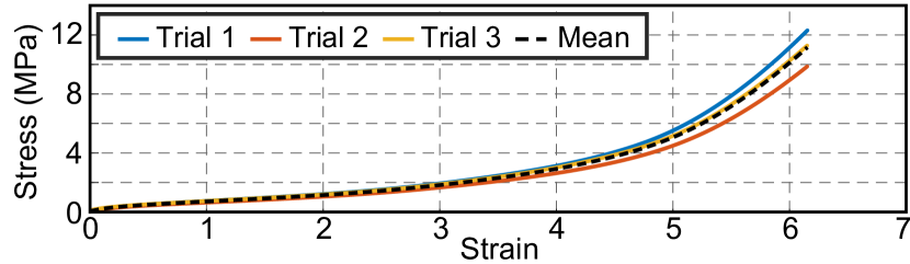
Experimental testing of the elastomers, Fig. S2, shows the maximum specific energy is 15800.3 J/kg. The utilized bands were found to have an average max stress and strain at 11.2 MPa and 6.2 respectively. For our robot platform the bands can only see a maximum strain of 2.1. At that point an average stress of 1.2 MPa is expected and an average specific energy of 1307.9 J/kg. The robot platform possesses 6 bands which can store at the strain of 2.1 an average energy of 16.63 J, at the total robot mass of 696.55 g that correlates to an average total system specific energy of 23.87 J/kg.
References
- [1] R. Armour, K. Paskins, A. Bowyer, J. Vincent, W. Megill, and R. Bomphrey, “Jumping robots: a biomimetic solution to locomotion across rough terrain.” Bioinspiration & biomimetics, vol. 2, no. 3, pp. 65–82, sep 2007.
- [2] C. Zhang, W. Zou, L. Ma, and Z. Wang, “Biologically inspired jumping robots: A comprehensive review,” Robotics and Autonomous Systems, vol. 124, p. 103362, 2020.
- [3] E. W. Hawkes, C. Xiao, R.-a. Peloquin, C. Keeley, M. R. Begley, M. T. Pope, and G. Niemeyer, “Engineered jumpers overcome biological limits via work multiplication,” Nature, vol. 604, no. April, 2022.
- [4] Boston Dynamics, “Sandflea,” 2013.
- [5] M. Kovac, M. Fuchs, A. Guignard, J.-C. Zufferey, and D. Floreano, “A miniature 7g jumping robot,” IEEE International Conference on Robotics and Automation, pp. 373–378, may 2008.
- [6] V. Zaitsev, O. Gvirsman, U. Ben Hanan, A. Weiss, A. Ayali, and G. Kosa, “A locust-inspired miniature jumping robot,” Bioinspiration & Biomimetics, vol. 10, no. 6, p. 066012, 2015.
- [7] B. Shin, H.-Y. Kim, and K.-J. Cho, “Towards a biologically inspired small-scale water jumping robot,” IEEE RAS & EMBS International Conference on Biomedical Robotics and Biomechatronics, pp. 127–131, oct 2008.
- [8] W. a. Churaman, A. P. Gerratt, and S. Bergbreiter, “First leaps toward jumping microrobots,” IEEE/RSJ International Conference on Intelligent Robots and Systems, vol. 2, no. 2, pp. 1680–1686, sep 2011.
- [9] M. Noh, S.-W. Kim, S. An, J.-S. Koh, and K.-J. Cho, “Flea-Inspired Catapult Mechanism for Miniature Jumping Robots,” IEEE Transactions on Robotics, vol. 28, no. 5, pp. 1007–1018, oct 2012.
- [10] W. a. Churaman, L. J. Currano, C. J. Morris, J. E. Rajkowski, and S. Bergbreiter, “The First Launch of an Autonomous Thrust-Driven Microrobot Using Nanoporous Energetic Silicon,” Journal of Microelectromechanical Systems, vol. 21, no. 1, pp. 198–205, feb 2012.
- [11] J. S. Koh, S. P. Jung, M. Noh, S. W. Kim, and K. J. Cho, “Flea inspired catapult mechanism with active energy storage and release for small scale jumping robot,” IEEE International Conference on Robotics and Automation, pp. 26–31, 2013.
- [12] F. Li, G. Bonsignori, U. Scarfogliero, D. Chen, C. Stefanini, W. Lui, P. Dario, and X. Fu, “Jumping mini-robot with bio-inspired legs,” IEEE International Conference on Robotics and Biomimetics, pp. 933–938, feb 2009.
- [13] J. Zhao, J. Xu, B. Gao, N. Xi, F. J. Cintr, M. W. Mutka, and L. Xiao, “MSU Jumper: A Single-Motor-Actuated Miniature Steerable Jumping Robot,” IEEE Transactions on Robotics, vol. 29, no. 3, pp. 602–614, 2013.
- [14] M. M. Plecnik, D. W. Haldane, J. K. Yim, and R. S. Fearing, “Design exploration and kinematic tuning of a power modulating jumping monopod,” Journal of Mechanisms and Robotics, vol. 9, no. 1, pp. 1–13, 2017.
- [15] P. Fiorini and J. Burdick, “The Development of Hopping Capabilities for Small Robots,” Autonomous Robots, pp. 239–254, 2003.
- [16] J. Zhao, R. Yang, N. Xi, B. Gao, X. Fan, M. W. Mutka, and L. Xiao, “Development of a miniature self-stabilization jumping robot,” IEEE/RSJ International Conference on Intelligent Robots and Systems, pp. 2217–2222, oct 2009.
- [17] U. Scarfogliero, C. Stefanini, and P. Dario, “Design and Development of the Long-Jumping ” Grillo ” Mini Robot,” IEEE International Conference on Robotics and Automation, no. April, pp. 10–14, 2007.
- [18] T. Ho and S. Lee, “A Novel Design of a Robot That Can Jump and Roll with a Single Actuator,” IEEE/RSJ International Conference on Intelligent Robots and Systems, pp. 908–913, 2012.
- [19] J. Aguilar and D. I. Goldman, “Robophysical study of jumping dynamics on granular media,” Nature Physics, vol. 12, no. 3, pp. 278–283, 2016.
- [20] A. Yamada, M. Wataril, H. Mochiyama, and H. Fujimoto, “A Jumping Robot based on the Closed Elastica,” International Symposium on Micro-NanoMechatronics and Human Science, pp. 604–609, 2007.
- [21] A. Yamada, M. Watari, H. Mochiyama, and H. Fujimoto, “An asymmetric robotic catapult based on the closed elastica for jumping robot,” IEEE International Conference on Robotics and Automation, pp. 232–237, may 2008.
- [22] A. Yamada, H. Mameda, H. Mochiyama, and H. Fujimoto, “A Compact Jumping Robot utilizing Snap-through Buckling with Bend and Twist,” IEEE/RSJ International Conference on Intelligent Robots and Systems, pp. 389–394, 2010.
- [23] M. Kovac, M. Schlegel, J.-C. Zufferey, and D. Floreano, “A miniature jumping robot with self-recovery capabilities,” IEEE/RSJ International Conference on Intelligent Robots and Systems, pp. 583–588, oct 2009.
- [24] M. Kovac, M. Schlegel, J.-C. Zufferey, and D. Floreano, “Steerable miniature jumping robot,” Autonomous Robots, vol. 28, no. 3, pp. 295–306, dec 2009.
- [25] J. Zhao, N. Xi, B. Gao, M. W. Mutka, and L. Xiao, “Design and testing of a controllable miniature jumping robot,” IEEE/RSJ International Conference on Intelligent Robots and Systems, pp. 3346–3351, oct 2010.
- [26] P. Fiorini, S. Hayati, M. Heverly, and J. Gensler, “A hopping robot for planetary exploration,” IEEE Aerospace Conference Proceedings, pp. 153–158 vol.2, 1999.
- [27] J. Zhao, N. Xi, B. Gao, M. W. Mutka, and L. Xiao, “Development of a controllable and continuous jumping robot,” IEEE International Conference on Robotics and Automation, pp. 4614–4619, may 2011.
- [28] J. Zhao, T. Zhao, N. Xi, M. W. Mutka, and L. Xiao, “MSU Tailbot : Controlling Aerial Maneuver of a Miniature-Tailed Jumping Robot,” IEEE/ASME Transactions on Mechatronics, pp. 1–12, 2015.
- [29] M. A. Woodward and M. Sitti, “Morphological intelligence counters foot slipping in the desert locust and dynamic robots,” Proceedings of the National Academy of Sciences, p. 201804239, 2018.
- [30] M. A. Woodward and M. Sitti, “Design of a miniature integrated multi-modal jumping and gliding robot,” IEEE/RSJ International Conference on Intelligent Robots and Systems, pp. 556–561, sep 2011.
- [31] M. Kovac, O. Fauria, J.-C. Zufferey, and D. Floreano, “The EPFL jumpglider: A hybrid jumping and gliding robot with rigid or folding wings,” IEEE International Conference on Robotics and Biomimetics, pp. 1503–1508, dec 2011.
- [32] M. A. Woodward and M. Sitti, “MultiMo-Bat: A biologically inspired integrated jumping-gliding robot,” The International Journal of Robotics Research, vol. 33, no. September, pp. 1511–1529, 2014.
- [33] A. L. Desbiens, M. Pope, F. Berg, Z. E. Teoh, J. Lee, and M. Cutkosky, “Efficient Jumpgliding : Theory and Design Considerations,” IEEE International Conference on Robotics and Automation, pp. 4436–4443, 2013.
- [34] A. L. Desbiens, M. T. Pope, D. L. Christensen, E. W. Hawkes, and M. R. Cutkosky, “Design principles for efficient, repeated jumpgliding.” Bioinspiration & biomimetics, vol. 9, no. 2, p. 025009, 2014.
- [35] A. Beck, V. Zaitsev, U. B. Hanan, G. Kosa, A. Ayali, and A. Weiss, “Jump stabilization and landing control by wing-spreading of a locust-inspired jumper,” Bioinspiration & Biomimetics, vol. 12, 2017.
- [36] M. A. Woodward and M. Sitti, “Tailored Magnetic Springs for Shape-Memory Alloy Actuated Mechanisms in Miniature Robots,” IEEE Transactions on Robotics, vol. 35, no. 3, pp. 589–601, 2019.
- [37] B. Zhu, J. Xu, A. Charway, and D. Saldana, “PogoDrone: Design, Model, and Control of a Jumping Quadrotor,” Proceedings - IEEE International Conference on Robotics and Automation, pp. 2031–2037, 2022.
- [38] B. G. A. Lambrecht, A. D. Horchler, and R. D. Quinn, “A Small , Insect-Inspired Robot that Runs and Jumps,” IEEE/RSJ International Conference on Intelligent Robots and Systems, pp. 40–45, 2005.
- [39] A. M. Johnson and D. E. Koditschek, “Toward a vocabulary of legged leaping,” Proceedings - IEEE International Conference on Robotics and Automation, pp. 2568–2575, 2013.
- [40] A. L. Brill, A. De, A. M. Johnson, and D. E. Koditschek, “Tail-assisted rigid and compliant legged leaping,” IEEE International Conference on Intelligent Robots and Systems, vol. 2015-Decem, pp. 6304–6311, 2015.
- [41] G. P. Jung, C. S. Casarez, S. P. Jung, R. S. Fearing, and K. J. Cho, “An integrated jumping-crawling robot using height-adjustable jumping module,” Proceedings - IEEE International Conference on Robotics and Automation, vol. 2016-June, pp. 4680–4685, 2016.
- [42] S. a. Stoeter and N. Papanikolopoulos, “Autonomous stair-climbing with miniature jumping robots.” IEEE Transactions on Systems, Man, and Cybernetics, vol. 35, no. 2, pp. 313–325, apr 2005.
- [43] Y. Ho, S. Kyoung, T. Jin, J. H. Lee, J. Y. Choi, C. H. Yim, and D. H. Kim, “Mecianism and Control of a Jumping Robot,” in International Conference on Control, Automation and Systems 2007, 2007, pp. 2499–2502.
- [44] M. T. Tolley, R. F. Shepherd, M. Karpelson, N. W. Bartlett, K. C. Galloway, M. Wehner, R. Nunes, G. M. Whitesides, and R. J. Wood, “An Untethered Jumping Soft Robot *,” IEEE International Conference on Intelligent Robots and Systems, pp. 4–9, 2014.
- [45] N. W. Bartlett, M. T. Tolley, J. T. B. Overvelde, J. C. Weaver, B. Mosadegh, K. Bertoldi, G. M. Whitesides, and R. J. Wood, “A 3D-printed, functionally graded soft robot powered by combustion,” Science, vol. 349, no. July, pp. 161–165, 2015.
- [46] M. H. Raibert, “Hopping in Legged Systems—Modeling and Simulation for the Two-Dimensional One-Legged Case,” IEEE Transactions on Systems, Man and Cybernetics, vol. SMC-14, no. 3, pp. 451–463, 1984.
- [47] M. H. Raibert, H. B. Brown, and M. Chepponis, “Experiments in Balance with a 3D One-Legged Hopping Machine,” The International Journal of Robotics Research, vol. 3, no. 2, pp. 75–92, 1984.
- [48] D. W. Haldane, M. M. Plecnik, J. K. Yim, and R. S. Fearing, “Robotic vertical jumping agility via Series-Elastic power modulation,” Science Robotics, vol. 1, no. 1, 2016.
- [49] E. Ambrose and A. D. Ames, “Improved Performance on Moving-Mass Hopping Robots with Parallel Elasticity,” Proceedings - IEEE International Conference on Robotics and Automation, pp. 2457–2463, 2020.
- [50] D. W. Haldane, J. K. Yim, and R. S. Fearing, “Repetitive extreme-acceleration ( 14-g ) spatial jumping with Salto-1P,” Submitted to IEEE Int. Conf. Intell. Robots. Syst., pp. 3345–3351, 2017.
- [51] J. K. Yim, B. R. P. Singh, E. K. Wang, R. Featherstone, and R. S. Fearing, “Precision robotic leaping and landing using stance-phase balance,” IEEE Robotics and Automation Letters, vol. 5, no. 2, pp. 3422–3429, 2020.
- [52] A. Sayyad, B. Seth, and P. Seshu, “Single-legged hopping robotics research - A review,” Robotica, vol. 25, no. 5, pp. 587–613, 2007.
- [53] B. A. Christensen, D. C. Lin, M. J. Schwaner, and C. P. McGowan, “Elastic energy storage across speeds during steady-state hopping of desert kangaroo rats (Dipodomys deserti),” Journal of Experimental Biology, vol. 225, no. 2, 2022.
- [54] H. Okubo and E. Nakano, “Design of a Jumping Machine Using Self-energizing Spring,” pp. 186–191, 1996.
- [55] U. Scarfogliero, C. Stefanini, and P. Dario, “A bioinspired concept for high efficiency locomotion in micro robots: the jumping Robot Grillo,” IEEE International Conference on Robotics and Automation, no. May, pp. 4037–4042, 2006.
- [56] R. M. Alexander, Principles of Animal Locomotion. Princeton University Press, 2003.
- [57] S. Bouabdallah, R. Siegwart, and G. Caprari, “Design and control of an indoor coaxial helicopter,” IEEE International Conference on Intelligent Robots and Systems, no. April, pp. 2930–2935, 2006.
- [58] R. Mahony, V. Kumar, and P. Corke, “Multirotor aerial vehicles: Modeling, estimation, and control of quadrotor,” IEEE Robotics and Automation Magazine, vol. 19, no. 3, pp. 20–32, 2012.