xxxxx, xxxxx, xxxx
S. Beregi
Real-time hybrid testing using iterative control for periodic oscillations
Abstract
Real-time hybrid testing is a method in which a substructure of the system is realised experimentally and the rest numerically. The two parts interact in real time to emulate the dynamics of the full system. Such experiments however are often difficult to realise as the actuators and sensors, needed to ensure compatibility and force-equilibrium conditions at the interface, can seriously affect the predicted dynamics of the system and result in stability and fidelity issues. The traditional approach of using feedback control to overcome the additional unwanted dynamics is challenging due to the presence of an outer feedback loop, passing interface displacements or forces to the numerical substructure. We, therefore, advocate for an alternative approach, removing the problematic interface dynamics with an iterative scheme to minimise interface errors, thus, capturing the response of the true assembly. The technique is examined by hybrid testing of a bench-top four-storey building with different interface configurations, where using conventional hybrid measurement techniques is very challenging. A case where the physical part exhibits nonlinear restoring force characteristics is also considered. These tests show that the iterative approach is capable of handling even scenarios which are theoretically infeasible with feedback control.
keywords:
real time hybrid testing, hybrid experiment, iterative control1 Introduction
Carrying out experiments on large-scale structures is challenging in engineering, as the instrumentation, production, moving and transportation of large prototypes is usually very costly and time-consuming. Thus, in many cases, a full-scale physical experiment it is not feasible. To address these challenges, one may conduct a physical test on particular substructures of a large-scale assembly. However, the tested substructure is likely to behave differently to the full-scale tests because boundary conditions are not consistent with the full structure.
In contrast, numerical simulations of engineering structures are inexpensive and there is much flexibility to try different concepts and designs for a product. While a full-numerical test is usually cost-effective, physical experiments are required for validating these ‘numerical twins’ of the physical structures. Thus, it is not entirely possible to eliminate the challenges with physical experiments mentioned above.
Real-time hybrid testing (a sub-field within dynamic substructuring; Allen et al. (2020)) is a part experimental, part numerical approach to obtain the dynamic response of an engineering structure, where only a part of the tested assembly is physically realised, whereas the other part is simulated. It naturally follows from this concept that, in order to replicate the dynamic behaviour of the true assembly, the physical substructure has to interact in real-time with the numerical half of the model.
A hybrid experiment may be useful in several scenarios, especially during the design of an engineering product. A physical-numerical hybrid test can be a more flexible alternative to a full-scale experiment since it allows for testing components in different environments without the need to physically realise every scenario or environment considered of interest. Thus, the hybrid testing concept can enable significant savings in experimental costs.
Thanks to its advantages, hybrid testing sparked significant interest in engineering and several previous experimental studies were carried out to investigate dynamic substructuring in various scenarios. The range of use cases includes civil engineering (Qian et al. (2014); Gao et al. (2013); Miraglia et al. (2020)), mechanical- (vand der Seijs et al. (2013); Nicgorski and Avitabile (2010); Meggitt et al. (2018)) or vibro-acoustic systems (Rixen et al. (2006)). There are also examples of use with problems including coupled physics, e.g. structural and aero- or fluid dynamics, such as in case of an aircraft wing Ruffini et al. (2020) or floating wind turbines Bachynski et al. (2015).
Real-time hybrid testing takes a similar approach to hardware-in-the-loop experiments, where a physical structure interacts with a simulated environment. While the two concepts are similar, the contrast between the two techniques can be found in the areas of application. Typical examples for the hardware-in-the-loop testing approach are mechatronic (electrical-mechanical) system testing, e.g. flight or driving simulators Isermann et al. (1999). In principle, adopting the same idea to test mechanical structures in a hybrid experimental environment is straightforward. However, the interface dynamics in mechanical hybrid experiments is often non-negligible and has a significant effect on the overall test dynamics Horiuchi et al. (1999).
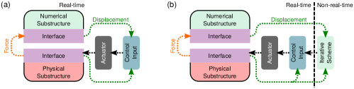
The advantages of real-time hybrid testing though come with challenges as well, which make the realisation of such hybrid experiments difficult. In mechanical structures, real-time data from the physical substructure is typically collected by electrodynamic transducers, e.g. piezoelectric load cells or accelerometers, and fed to the simulated part of the system. In the opposite direction across the interface, actuators are used to impose the behaviour of the numerical substructure on the physical experiment. This leads to a feedback-loop as illustrated by panel (a) in Fig. 1. Note that, here, we depict a displacement control based set-up, it is also possible to feed displacement to the numerical substructure and then use the actuator to impose a force on the physical substructure.
Interface errors inevitably lead to fidelity issues, since the behaviour of the true hybrid system with the interface dynamics is always different (to some degree) than that of the true assembly. In Insam and Rixen (2022), the fidelity issue in real-time substructuring tests is considered and an error quantification method is proposed. Nevertheless, in some cases, one may not just simply perceive an error in the response of the hybrid system, but the contribution of the actuator dynamics often leads to instabilities related to the feedback-loop which can make the hybrid experiment potentially infeasible. Instabilities in substructuring may be encountered even in conceptually simple systems, cf., previous studies on theoretical substructurability of low-degree-of-freedom mass-spring-damper systems Terkovics et al. (2016), a coupled oscillator-pendulum system Tu et al. (2013), and cantilever-beam with a PDE model Kyrychko et al. (2007). In analyses focusing on transducer-induced instabilities, it is commonplace to approximate the interface error as a time-delayed response and perform stability analysis on the resulting system of delay differential equations Hale and Lunel (1993).
The standard way of reducing interface error is using interface control Ruffini et al. (2020); Gawthrop et al. (2007) and/or an inverse-model-based compensation technique, relying on the thorough identification of the actuator dynamics. By means of this approach, one may employ model predictive control (see Wallace et al. (2005) and Tsokanas et al. (2022)) to compensate the phase lag induced by the actuators. For time-delayed systems in particular, one may also consider using the technique of finite spectrum assignment Manitius and Olbrot (1979). This method however can be very cumbersome, as it requires thorough system identification, which can involve inaccuracies and has to be performed repeatedly every time the experimental setup is changed.
To tackle the above limitations, we propose an alternative, iterative approach for hybrid experiments excited periodically. This approach removes the interface from the feedback-loop, thus, avoiding potential stability issues involved. Instead, we provide the controller with a periodic demand and monitor the response, updating the harmonic amplitudes of the demand in non-real-time until the interface compatibility and equilibrium is ensured. The closest existing work in the literature is Witteveen et al. (2022), where they successfully realise a non-simultaneous hybrid experiment, testing a physical shock absorber with a numerical wheel-suspension model. In their study, Witteveen et al. transform the coupling errors into the frequency domain, and use an iterative technique to establish the required forcing input to eliminate it. Note that the concept of hybrid testing in the frequency domain is also well-established in the literature with off-line FRF-based approaches such as Rixen and van der Valk (2013); Geradin and Rixen (2018) and, modal approaches Allen et al. (2007); it is one of the standard techniques in the field.
Here we propose a different approach inspired by control-based continuation Sieber and Krauskopf (2008), a technique for experimentally tracking limit cycles in nonlinear systems (both stable and unstable). The method employs a iteration to find the control target ensuring that the control converges to the same steady-state response as would be the case in the original system.
By capturing the FRF of the true assembly for an excitation with a stepped frequency, we treat the hybrid experiment as a varying parameter problem. We demonstrate the usefulness of this feature, by taking advantage of the original idea of the iterative approach coming from experimental bifurcation analysis. Thus, the method is capable of performing hybrid testing for structures with a nonlinear restoring force characteristics.
In this study, we use the example of a bench-top-sized 4-storey building to demonstrate the versatility and effectiveness of the iterative hybrid testing technique. Similar structures have been already used in studies on dynamic substructuring (e.g. Tian et al. (2020)) exploiting the easily describable dynamic response, namely, the behaviour of the 4-storey structure can be well-characterised by a 4 degree-of-freedom (DoF) model with concentrated mass, damping and stiffness parameters Dal Borgo et al. (2020); Gardner et al. (2020, 2022). The main challenge is that imperfect control compensation for the actuator dynamics leads to a mismatch across the interface and hence a misrepresentation of the dynamics of the structure being emulated. We first show that even for this conceptually simple structure, real-time feedback control of the hybrid test is very challenging and infeasible for some parameter ranges. We then demonstrate the effectiveness and versatility of the new proposed approach by performing dynamic substructuring experiments.
The rest of the paper is constructed as follows. In Section 2, we present the mathematical model of real-time hybrid testing with time-delayed-feedback from the numerical substructure and analyse the theoretical substructurability by performing a stability analysis on the hybrid system. In Section 3, we introduce the iterative algorithm eliminating direct feedback and the related instability from the structure. Section 4 presents the experimental setup which was used to produce the experimental results shown in Section 5. We first demonstrate successful implementation of the iterative hybrid testing approach on the linear system before extending the study to a weakly nonlinear version of the structure. The conclusions are given in Section 6.
2 Mathematical modelling
2.1 The time-delayed model of a real-time hybrid test
In this section, a mathematical model of the full hybrid system will be developed and examined to explore the control challenge discussed in the introduction. We note that for a real test, a full model of the system may not be available. The motivation to conduct a hybrid test is often due to challenges with modelling components of the physical substructure, hence it being represented experimentally. Here, to allow us to analyse the hybrid test approach, we will consider a system that can be represented numerically. We consider an -degree-of-freedom (DoF) linear dynamical system as the true assembly we would like to emulate with a part physical, part numerical experiment. Note that hybrid testing may be realised for more complex, in particular, nonlinear models; nevertheless, we consider a general linear case as it allows us to highlight the challenge without additional algebraic complexity.
The position and orientation of the true assembly is described by the vector of generalised coordinates where the individual generalised coordinates are usually chosen to fully define the system with the minimal number of coordinates. Thus, the equations of motion can be given in the matrix form
| (1) |
where and are the mass, damping and stiffness matrices, respectively, (), whereas describes external forcing applied to the structure.
In the hybrid experiment, only a part of the true assembly is represented in the physical substructure – this does not require a model in the hybrid test but to analyse the system, it will be represented by of the DoFs in the full model – the rest is replaced by a numerical model, referred to as the DoF numerical substructure. The compatibility of the physical and the numerical substructures is ensured by shared degrees-of-freedoms. The corresponding rigid bodies are referred to as the interface and distinguished from the internal parts of the two substructures. As such, the sum of the DoF of the two substructures is larger than (the DoF of the true assembly) by , i.e. .
The hybrid testing concept assumes that the two parts are clearly separable which is ensured by the coefficient matrices and in Eq. (1) having a block diagonal structure
| (2) |
where , and . In the formulae presented here, the bullets stand for the corresponding block of and ; e.g., for the mass matrix, is interpreted as . We mark the matrix-blocks corresponding to the physical and numerical substructures with red, green boxes, respectively. Notice that the interface element of the coefficient matrices is split between the physical and the numerical substructures. Thus, the two substructures should be considered such that the sum of the corresponding elements is equal to that of the true assembly .
The equations of motion of the physical and numerical substructures can be therefore expressed as
| (3) |
and
| (4) |
respectively. In the equations above, and contain the generalised coordinates corresponding to the internal part and the interface of the physical substructure,
| (5) |
and similarly, and represent the generalised coordinates of the interface and the internal part of the numerical substructure
| (6) |
To replicate the behaviour of the true assembly by the hybrid system, the motion of the interface in the physical and numerical substructures should be synchronised. In the substructurability analysis we consider the approach of feedback control, using force-feedback from the physical to the numerical substructure, and displacement feedback from the numerical to the physical substructure, cf. panel (a) in Fig. 1. Since sensors tend to introduce negligible phase-lag, we assume the force-feedback from the physical to the numerical substructure to be real-time; thus, the corresponding physical and numerical coupling forces are equal and point in the opposite direction
| (7) |
Conversely, we consider a time-delayed displacement feedback from the numerical to the physical subsystem, which can be expressed by the delayed displacement coupling condition
| (8) |
where denotes the feedback time-delay. The physical-background of the delayed feedback is rooted in sensor-dynamics, sampling and signal processing times, filtering delays, and actuator dynamics. While the contribution of these effects can differ in every experiment, since the aim of our study is to demonstrate the challenges of feedback-based real-time hybrid testing in the qualitative sense, we consider a single time delay in our model.
Expressing the coupling force from the second row of Eq. (3), and substituting in the delayed displacement coupling condition we obtain
| (9) |
Then, using the force coupling condition, we can substitute the expression above into the right-hand-side of Eq. (4). As a result, using the first row of Eq. (3) and the whole matrix formula in Eq. (4) we can compose the equation of motion for substructuring with delayed displacement-feedback
| (10) |
where, the vector of generalised coordinates is given by
| (11) |
while using bullets to represent the corresponding non-zero elements of each, the delayed and real-time mass, damping and stiffness matrices and can be given in the structure
| (12) |
while the forcing vector reads
| (13) |
As a result of the time-delayed displacement feedback, time delays appears in the states and time derivatives of state variables both in the equation of motion Eq. (10), leading to differential equations of neutral type. In a neutral type equation, the infinitely many eigenvalues accumulate at a constant in the complex plane as (Kyrychko et al. (2009)). This means that stable parameter-combinations are only possible if the asymptote at which the eigenvalues accumulate is in the negative-real half-plane. This, as we will demonstrate, gives rise to a condition on the mass matrices and As such, it is expected that only certain mass-ratios will be substructurable, whereas the system will be unconditionally unstable for others.
2.2 Theoretical substructurability analysis of multi-storey buildings
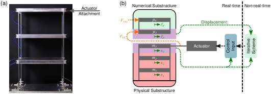
Our demonstrative example for real-time hybrid testing is a bench-top-sized four-storey building model. For the purpose of the substructurability analysis with delayed feedback, we consider a 4 degree-of-freedom lumped parameter model of the structure. The true assembly is split into two substructures at the third storey. The first and second storeys correspond to the physical substructure, the fourth storey to the numerical substructure, whereas the third storey serves as the interface. The model of the substructured assembly is depicted in Fig. 2. Following the notation introduced in Section 2.(a), this means that out of the DoF of the true assembly, is associated with the physical part, with the numerical part, while third storey’s displacement being an interface coordinate ().
In the equation of motion, we refer by and , to the masses, viscous damping and stiffness parameters of the physical side of the model, with the indices pointing to the storey each concentrated parameter element corresponds to. The equivalent parameters on the numerical side are denoted by , and (), for mass, damping and stiffness, respectively. The displacements of the physical storeys are given by the generalised coordinates , while the numerical displacements are referred to as .
To describe the motion of the substructured system, the following generalised coordinates are used: the physical displacements and and the numerical displacements and . These are represented in the vector of generalised coordinates.
| (14) |
We assume that the displacement of the third storey of the physical structure is constrained to the displacement of its numerical counterpart.
Thus, the equations of motion of the true assembly can be given in the matrix form as seen in Eq. (1). The mass matrix reads
| (15) |
whereas the damping and stiffness matrices are given by
| (16) |
We mark the parts of the interface term belonging to the physical and numerical substructures by red and green, respectively. Using the derivations presented in Section 2.1, one can give the governing equations of the substructured system in the same form as indicated by Eq. (10).
2.3 Stability analysis
The substructurability of the four-storey building is assessed by the stability analysis of the trivial equilibrium of the system given in (10). By using the exponential trial solution Hale and Lunel (1993), one obtains the characteristic equation , where the characteristic function reads
| (17) |
2.3.1 Stability boundaries
Stability boundaries may occur where the system has one or more characteristic exponent(s) with a zero real part, i.e. . This either implies a single root , or a complex-conjugate root pair . The case of a single real characteristic exponent is associated with ‘static’ loss of stability. With this substitution we obtain
| (18) |
One can find boundaries corresponding to pure complex characteristic exponents numerically, using the multi-dimensional bisection method Bachrathy and Stepan (2012), an extension of the bisection root-finding algorithm for multivariate implicit equation-systems.
With the physical stiffness parameters being positive this would only be the case if the numerical stiffness parameter was chosen to be zero. This case can be discarded as realistic parameters () are of interest.
Loss of stability may also happen through exponentially increasing oscillations if a complex conjugate pair of characteristic exponents crosses the imaginary axis (). Such boundaries can be found by solving the transcendental equation
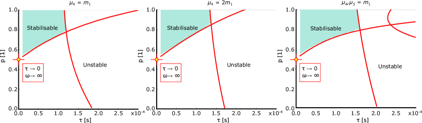
Considering the physical substructure with the parameters given in Table 1 and selecting the parameters Ns/m and N/m for the numerical damping and stiffness, boundaries were searched for in the parameter domain defined by the limits , , . These boundaries are shown in red in the stability charts in Fig. 3.
To demonstrate that the results on the effect of imperfect interface control are transferable to other hybrid testing scenarios, we present the stabilisability chart for the case when the numerical substructure has an extra DoF, thus simulating a five-storey building. We abstain from expressing the governing equations for this case; nevertheless, they are straightforward to derive based on those of the four-storey building. The stabilisability chart for the five-storey structure with the parameters , , describing the additional top storey is presented in the right panel of Fig. 3. The structure of the stabilisability charts is very similar for the four- and five-storey structures suggesting that the instability is intrinsic to the imperfect interface control and similar effects are to be expected for other hybrid testing set-ups with a full-feedback control.
| 1st storey () | 5.37 kg | 4.4062 Ns/m | 53048 N/m |
|---|---|---|---|
| 2nd storey () | 5.37 kg | 3.7979 Ns/m | 45724 N/m |
| 3rd storey () | 5.37 kg | 3.7421 Ns/m | 45052 N/m |
Knowing the boundaries from Eq. (18) does not reveal the stability of the system in the resulting parameter-domains. Therefore, the different parameter-domains are labelled as stabilisable/unstable by semi-discretisation Insperger and Stepan (2002) a method of generating a set of (discretised) equations from the underlying infinite dimensional delay equation using Chebyshev polynomials Breda et al. (2016); Trefethen (2000). Thus, the infinite dimensional time-delay system is approximated by a large-dimensional system of ordinary differential equations. This system can be given in the form , and the stability of the trivial equilibrium can be investigated by calculating the largest real-part of eigenvalues of the coefficient-matrix . We say that the hybrid system is stabilisable if the trivial equilibrium in the semi-discrestised model is stable. This is due to the fact that in the real-life experiment, stability is also subject to using a suitable control algorithm to impose feedback from the numerical substructure on the physical substructure. The unstable domains in Fig. 3 are white whereas the stabilisable ones are indicated by green shading. The boundaries identified with the two different methods show a good agreement as there are only minor differences between the stabilisable domains identified with semi-discretisation and the curves obtained directly from the characteristic function , which can be accounted for the semi-discretised system being an approximation of the time-delay model.
It is worth mentioning that both numerical methods have limitations in obtaining the stability boundaries at small time delays (). This is due to the fact, that the semi-discretised approximation of the time-delay system has a singularity at . (One may overcome this shortcoming of the semi-discretisation by using linear multi-step methods to calculate the rightmost eigenvalue of the delay differential equation Engelborghs and Roose (2002).) Another limitation of the numerical root-finding algorithms employed is that it requires a pre-defined domain in which solutions are searched for which makes it infeasible to find the stability boundaries from the characteristic equation, since solutions near involve large frequencies (). Instead, for this case, we carry out an asymptotic estimation of the boundaries.
2.3.2 Asymptotic calculation of the boundary at
Even though an analytical solution is not available for the stability boundaries, an asymptotic calculation can be carried out for the case of oscillatory loss of stability () for and .
In this case, the characteristic function tends to
| (19) |
Using Euler’s formula for the complex exponential this can be expressed as
| (20) |
If with (albeit is very large while is very small, their product may be in leading order); then and . Thus, the equation above yields to
| (21) |
which leads to
| (22) |
As indicated in Fig. 3, this analytical boundary is in good agreement with the numerical results, and it may also serve as a rule of thumb: substructuring with delayed feedback is infeasible if the mass in the physical part is larger than in the numerical part, i.e. if . Nevertheless, the numerical results indicate that the maximum time-delay allowed in the feedback loop is very limited (in the order of 0.1 ms) even for the mass-ratios where substructuring is theoretically possible. This means that realising a dynamic hardware-in-the-loop test with a close feedback loop is very challenging and essentially has to rely on the compensation of the actuator dynamics.
3 Methodology – Hybrid-testing without direct feedback
As shown in Section 2, most of the difficulties in real-time dynamic substructuring of the 4-storey building arise in the feedback from the numerical to the physical substructure due to the actuator dynamics. Thus, we address these challenges by adopting a measurement strategy that breaks the feedback loop and replaces it with an iteration ensuring the synchronous motion of the physical and the numerical sides of the interface. This concept is presented in panel (b) of Fig. 1.
The idea of using an iteration is adopted from the control-based continuation technique Sieber and Krauskopf (2008) which was originally developed to trace both stable and unstable periodic solutions in nonlinear experiments employing stabilising and non-invasive control to the observed structure; the non-invasiveness of the control ensures that the steady-state behaviour of the system is identical to that of the open-loop system, changing the stability of steady-states but preserving their location in state-space. In control-based continuation, the control target and the steady state system response is considered by their truncated Fourier series, allowing for the construction of an algebraic root-finding problem. Then an iteration is used to find the appropriate Fourier coefficients of the control target ensuring the non-invasiveness of the control, i.e., that the captured steady-state response of the controlled system is the same as the one of the open-loop system.
A similar strategy is proposed for the dynamic substructuring experiment. We take the iterative approach to find the steady-state response of the physical-numerical hybrid system to periodic forcing, i.e. its frequency response function while we disregard the transient response. Since, as a result, both the forcing and the steady-state system response will be periodic, the Fourier coefficients can be used to consider an algebraic zero-problem as in control-based continuation. This potentially allows for high-fidelity steady-state testing which is ideal in engineering applications where the FRF is more often of interest than the transients, as in product design or prototype testing, avoiding resonance is usually a fundamental requirement.
The methodology described below does not depend on the linearity of the system; the use of a Newton iteration allows nonlinear system interactions to be handled.
3.1 Iterative root-finding and continuation
To match the physical and numerical displacements and , which correspond to the interface storey of the assembly, we employ an iterative approach in the substructuring experiment. We consider a scenario when the hybrid structure is subject to periodic forcing (applied on the 4th storey). As such, we expect a periodic response in steady state. This allows us to consider the displacements at the physical and numerical sides of the interface by means of their truncated Fourier series
| (23) |
| (24) |
If the tested structure is linear, then the higher harmonics () in the steady state response are small and practically negligible (inevitably, non-idealities in the experiment generate some higher harmonics). The static components and of the displacement signals are also discarded from the iteration. In case of the physical substructure, we assume that if the static part of the forcing from the shaker is not changing, the physical substructure oscillates around the static equilibrium whereas this is ensured by control in the numerical substructure.
In principle, the FRF of the hybrid system could be obtained by finding the appropriate phase and amplitude of the voltage signal sent to the actuator resulting in the synchronous motion of the physical and the numerical sides of the interface. However, since the physical structure is lightly damped, it is beneficial to apply a PD displacement control to the physical side of the interface and treat the control target as the unknown parameter of the substructuring experiment. As such, introducing further damping to the structure, the transients are reduced, steady-state is reached faster and the iteration can be performed with shorter waiting times. Accordingly, the demand signal sent to the actuator is given by the PD control law
| (25) |
where the control target is an arbitrary periodic function described by its Fourier series
| (26) |
The constants and are determined as part of the iterative scheme, as described below.
Similarly, we apply control to the numerical part of the structure as well to ensure the third (interface) storey oscillates around . This is necessary since the numerical substructure is not grounded. Without this grounding, the static error of the piezoelectric force and acceleration sensors as well as the error in the numerical integration would lead to an error in the displacement. The control-force applied to the numerical part of the third storey is determined by the PD control law
| (27) |
This definition ensures that the control applied to the numerical substructure is non-invasive, i.e., if the iteration ensures that the physical and the numerical displacements of the interface storey are equal in steady state, the control force vanishes and the response of the hybrid structure is equal to the one of the true assembly.
With these considerations, the aim of the iterative algorithm is to eliminate the error between the displacements of the physical and numerical 3rd storeys such that
| (28) |
Representing the steady-state solutions by their Fourier coefficients allows us to transform this into an algebraic problem where the error vector is defined by the difference of the corresponding Fourier coefficients
| (29) |
Here, and are the Fourier coefficients of the control target. The Fourier coefficients corresponding to the physical displacement and the numerical displacement are both functions of , defined implicitly through the behaviour of the physical substructure. Each time a new control target is set, the hybrid experiment equilibrates and new values for and are measured. This error vector is already suitable for ensuring the synchronous motion of the physical and the numerical 3rd storeys for a constant set of system parameters.
If the frequency response of the structure is a well-defined function (i.e. single valued) with respect to a system parameter of interest (e.g., the forcing frequency), the parameter domain can be swept to determine the overall behaviour. However, in the presence of weak nonlinearity hysteresis loops may form leading to a multi-valued frequency response. As such, we improve on this basic strategy by adding the pseudo arclength condition to the zero problem is Eq.(29). The pseudo-arclength method is a standard continuation strategy in numerical bifurcation analysis Seydel (2010), and can be employed by considering the extended error vector
| (30) |
where is a system parameter and the input vector is given by . The secant , is obtained by using the two previous solutions, is used to provide the predicted direction for the continuation of the solution branch. As such, the prediction of the next solution is calculated as , where the constant is used for step-size control.
Starting from a suitable initial condition , the solution of the extended zero-problem is found by a Newton-like iteration
| (31) |
In the original Newton method for nonlinear root-finding, stands for the Jacobian matrix. However, this is unavailable in experiments; therefore, a suitable proxy is used in the algorithm. At the first iteration step, is obtained by finite differences, which equals the same number of evaluations of the error vector (obtaining steady-state solutions for different inputs) as the problem dimension. Then, in the following steps () a Broyden update Broyden (1965) is used to the Jacobian which requires one evaluation at each step.
| (32) |
Since Newton-like root-finding methods are prone to overshooting (i.e., not converging due to taking too large steps) the algorithm is combined with line-search modifying the iteration step in Eq. (31) to
| (33) |
Initially, the next candidate solution is searched for with . If then this solution is accepted, if not, we retry with until a smaller error norm is achieved than in the previous step or the pre-set minimum value of the damping parameter is reached.
The iteration is either terminated upon reaching the given tolerances or exceeding the maximum number of iterations, in which case the solution is discarded. In this case, the continuation may progress by considering a smaller step-size from the previous point. The flowchart of the iterative method can be seen in Fig. 4.
4 Experimental investigation
4.1 Hybrid testing setup
In the dynamic substructuring experiment, we investigate a physical-numerical hybrid model of a bench-top-sized four-storey building. As shown in Figure 2. The physical substructure comprises the two bottom storeys and the legs of the physical structure whereas the third storey, attached to the shaker, serves as the interface between the physical and numerical substructures. The displacements of the three storeys of the physical substructure are measured by laser sensors. A piezoelectric force transducer is used to measure the force input from the shaker to the physical part which is fed to the real-time simulation of the numerical substructure. The acceleration of the three physical storeys are captured by accelerometers the signals of which can be used for compensating the inertial forces. This configuration allows for testing different mass-ratios of the physical and numerical parts of the third storey of the true assembly.
The numerical substructure comprises the third and fourth storeys of the building. The real-time simulation of the numerical model is realised by the real-time controller (RTC) unit which is also used for data acquisition. The RTC device is also responsible for controlling the shaker providing the control force to the physical system.
The RTC is connected to a PC which is used for data processing and determining the control target and parameters.
As shown in Fig. 2, in the hybrid testing setup, the connection of the physical and numerical substructures is realised by feeding the measured force at the interface to the numerical model, whereas the simulated displacement of the numerical third storey is imposed on the physical substructure by the shaker.
4.2 Simulation of the numerical substructure
The numerical substructure, as indicated in Fig. 2 , comprises a part of the 3rd and the 4th storeys of the building and the columns in between. This part of the structure is simulated by a 2 DoF numerical model which is subject to three external forces; the interface force , measured by the load cell in real-time, the control-force acting on the 3rd storey and, in the present measurement scenario, a periodic forcing on the 4th storey . The control-force is employed on the numerical structure to eliminate any static error in displacement due to the numerical structure being ungrounded and is designed such that it is non-invasive, i.e. it does not affect the steady state response of the hybrid structure.
Furthermore, to carry out hybrid testing for different mass ratios , we use the measured acceleration signal to compensate for a part of the inertial force coming from the physical side of the interface . Thus, the governing equations of the numerical model can be expressed as
| (34) |
and
| (35) |
where the external forces acting on the numerical 3rd storey are given by
| (36) |
Introducing new state variables , ,, , the governing equations of the numerical substructure can be re-written in the matrix form
| (37) |
This system is simulated using the implicit Euler scheme and so the subsequent values of the state variables are given by
| (38) |
with referring to the simulation time-step. Since the numerical substructure is linear, one can solve this equation for obtaining
| (39) |
The simulation of the numerical substructure is realised using the parameters listed in Table 2.
| 4th storey mass | 10.74 kg | |
|---|---|---|
| Numerical leg damping | 3.7421 Ns/m | |
| Numerical leg stiffness | 45052 N/m | |
| Forcing amplitude | 1 N | |
| Simulation timestep | s | |
| Physical proportional control gain | 100 V/m | |
| Physical derivative control gain | 10 Vs/m | |
| Numerical proportional control gain | 50000 N/m | |
| Numerical derivative control gain | 200 Ns/m |
5 Results
5.1 Frequency response of the hybrid system
Using the continuation algorithm, described in Section 3. 3.1, the frequency response of the 4-storey building was captured for periodic forcing applied to the 4th storey. The second bending mode of structure was considered, since the structure is effectively linear in this configuration, whereas the first bending mode showed noticeable nonlinearity. As such, only the fundamental harmonic components of the physical and numerical displacements were matched by the iterative algorithm (using in Eq. (29) and (30)). Using different masses in the numerical 4th storey and compensating for the inertial forces accordingly, we tested three different mass ratios of the numerical and physical sides of the interface: Case 1: p = 0.67 ( kg), Case 2: p = 0.5 ( kg), p = 0.33 ( kg). Meanwhile, the total mass of the 3rd storey was kept constant kg. As such, the three cases considered here can be interpreted as three different interface position, with the mass of the 3rd storey split between the physical and numerical substructures at different heights.
We draw attention to the fact that, as presented in Section 4, a necessary condition of stabilisability for closed-loop feedback control is . As such, if a traditional closed-loop feedback control was used for substructuring, Case 1 would be stabilisable, Case 2 corresponds to the theoretical lower limit for stabilisable mass ratios whereas Case 3 would be unconditionally unstable. In contrast, with the iterative approach, it was possible to capture the FRF for all cases irrespective of the interface position. Moreover, the good agreement between the cases with different mass ratios indicate that the algorithm results in minimal interface error and the results are representative of the behaviour of the true assembly.
Figure 5 shows the FRFs indicating the displacement amplitude for the 3rd, interface storey. The iterative technique is capable of finding the solution within or m tolerance (whichever is the higher) for the Fourier coefficients of fundamental harmonic component of the solutions, resulting in a very accurate match between the physical and numerical displacements. If error bars were used for Fig. 5, as in case of the nonlinear frequency response curve in Fig. 6, they would be smaller or similar in size to the markers in the diagram. Note that the experiment has less overall accuracy in terms of independent repeatability of the FRF. The overall errors however are intrinsic to the experiment (such as daily temperature changes and imperfect vibration isolation within the lab) and not introduced by the iterative scheme.
Identifying a valid data point in the FRF while performing the continuation typically requires 0-5 iterations for any mass-ratio, though there were occasional outliers which can be explained by the larger noise level the experiment is subject to at larger amplitudes. It is also worth noting that there is no significant difference in the performance of the iterative algorithm for the three different mass ratios, indicating that the iterative substructuring scheme performs evenly in the three cases. This is in contrast with the direct feedback-based approach, where e.g. the case would be theoretically impossible due to the actuator delay.
5.2 Frequency response of a structure with nonlinear restoring force
To further demonstrate the versatility of the iterative approach in substructuring, we performed hybrid testing with a modified physical substructure producing a nonlinear restoring force. To achieve this, stiff plates were added to the legs of the physical 3-storey structure to limit their effective length in one bending direction. This resulted in nonlinear stiffness as indicated in panel (c) of Fig. 6, showing the displacement difference between the second and third storeys for a range of static forcing. The measured nonlinear response is approximated by bilinear force characteristics which is consistent with a different effective length when the relative displacement is in one direction compared to the other direction. In order to trigger a nonlinear behaviour, a static force of 26.68 N was subjected to the structure by the shaker, leading to softening behaviour at larger amplitudes.
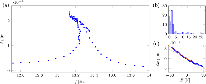
Panel (a) of Fig. 6 shows the FRF of the nonlinear structure with bars indicating magnified (2x) amplitude errors between the physical and numerical sides of the interface. Observe that the diagram includes a parameter domain where multiple solutions correspond to the same frequency. While the stability of the captured solutions is not investigated in the experiment, nonlinear system theory suggests that the high and low amplitude solutions are stable, whereas the solution-branch in the middle is unstable. Extracting information of such unstable limit cycles in nonlinear experiments is non-trivial as they cannot be found without control. Since the iterative substructuring method is derived from CBC it has the advantage over the direct feedback-based method that it is capable of finding even unstable limit cycles.
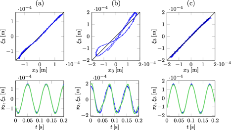
In Fig. 7, we compare the converged, steady-state solutions from the linear (column a) and the nonlinear (column b) case. In the two diagrams, we show two phase-plots of the physical and numerical displacements and in the top and bottom row of panels, respectively. In column (a), indicating a solution from the linear structure, only minor differences can be observed between the physical and numerical displacements, which are present mostly due to measurement and/or process noise or a weak effect of the higher harmonic components. Column (b) shows a case with more profound nonlinear behaviour. In this case, the fundamental harmonic components of the numerical and physical displacements are still matched but there is more prevalent difference in the higher (especially the second) harmonic as indicated by shape of the Lissajous plot Greenslade Jr (2018). These differences can be eliminated by further iterations incorporating the higher harmonic components also, as indicated by column (c), captured with the nonlinear physical substructure and at a similar vibration amplitude as in case (b). However, matching the higher harmonics takes significantly longer than just the fundamental harmonic component of the solution. Thus, this was not used when capturing the nonlinear FRF.
Note that the realisation of the nonlinear restoring force in the presented experiment has some limitations. Since the bi-linear response originates from contact-nonlinearity, the experiment is subject to a significantly higher level of noise and uncertainty in the nonlinear configuration than in the linear case. This is reflected by the histogram in panel (b) of Fig. 6 showing that, while in most cases the solution was found in 5 iterations, there were a considerable number of instances when a higher number of iteration steps was required. This is due to the higher fluctuation in the captured response, which limited the use of the pseudo-arclength continuation resulting in slightly poorer coverage of the response curve. As indicated by the larger error bars, these effects were strongest around the resonance peak. Therefore, the nonlinear response was captured by two continuations one approaching the peak from lower frequencies while the other from higher frequencies. Moreover, the higher fluctuation in the Fourier coefficients prevented the inclusion of the higher harmonics to the iteration, as since a higher-dimensional Jacobian matrix is increasingly difficult to obtain. Note that these issues could be addressed by employing specialist techniques (see Schilder et al. (2015)) for performing CBC in noisy or impacting systems involving higher uncertainty. Nevertheless, this was deemed outside the scope of the present study.
6 Conclusion
In this study, the dynamic substructuring of a bench-top-sized four-storey building is performed with the first two storeys fully physically realised, the third storey serving as the interface to the numerical substructure, and the top two storeys simulated. Using a time-delayed model to account for actuator dynamics, our study demonstrates that the hybrid experiment is very challenging and in some cases impossible to carry out with the classical approach using a full feedback-loop.
Instead, an iterative approach is proposed, breaking the feedback-loop between the numerical and the physical parts of the system, thus avoiding the related stability problems. We demonstrated that the iterative technique is capable of capturing the FRFs of the hybrid system with good accuracy without the risk of the feedback-related instability. The iterative approach also avoids the use of model-prediction techniques or other more sophisticated means of compensation for the actuator dynamics. Being a model-free technique also has the advantage that the iterative technique can handle various changes or different model configurations without major alternations to the algorithm. Thus, it is a versatile tool that may be employed when more traditional substructuring approaches fail. As the method is based on numerical continuation, it can be easily used to track the response of nonlinear functions, even unstable solutions which would be undetectable otherwise.
Nevertheless, certain scenarios are still difficult to handle, i.e. solutions or measurement setups involving a higher amount of noise, making it difficult to find the solution resulting in the synchronous motion of the physical and numerical sides of the interface by Newton-like iteration, as derivatives are especially sensitive to random perturbations. In further studies, these issues may be addressed by using surrogate models relying on sampled data from the experiment. Also, the effect of noise and model uncertainty can be addressed providing confidence intervals for the captured FRFs for the given noise level and uncertainty in the system. Finally, this approach has natural extensions to systems with multiple degrees-of-freedom at the interface; initial experiments can be found in Vizzaccaro et al. (2023).
The authors declare that this research and the presentation of its results is in line with the ethical standards of the Royal Society, no human or animal subjects were used and there are no ethical concerns related to biosecurity involved.
Data is available from the University of Bristol Data Repository at https://data.bris.ac.uk/data/
All authors contributed to the algorithm, experiment and manuscript development. S. Beregi carried out the experiments and wrote the manuscript.
There are no competing interests.
This research has received funding from the Digital twins for improved dynamic design (EP/R006768/1) EPSRC, United Kingdom grant. The support of the EPSRC is greatly acknowledged.
References
- Allen et al. [2007] M.S. Allen, D.C. Kammer, and R.L. Mayes. Comparison of frf and modal methods for combining experimental and analytical substructures. 25th international modal analysis conference (IMAC XXV), 2007.
- Allen et al. [2020] M.S. Allen, D. Rixen, M. van der Seijs, P. Tiso, T. Abrahamsson, and R.L. Mayes. Substructuring in Engineering Dynamics. Springer Nature Switzerland, Cham, Switzerland, 2020. ISBN 978-3-030-25531-2.
- Bachrathy and Stepan [2012] D. Bachrathy and G. Stepan. Bisection method in higher dimensions and the efficiency number. Periodica Polytechnica Mechanical Engineering, 56(2):81–86, 2012.
- Bachynski et al. [2015] E.E. Bachynski, V. Chabaud, and T. Sauder. Real-time hybrid model testing of floating wind turbines: Sensitivity to limited actuation. Energy Procedia, 80:2–12, 2015. https://doi.org/10.1016/j.egypro.2015.11.400.
- Breda et al. [2016] D. Breda, O. Diekmann, M. Gyllenberg, F. Scarabel, and R. Vermiglio. Pseudospectral discretization of nonlinear delay equations: new prospects for numerical bifurcation analysis. SIAM Journal on applied dynamical systems, 15:1–23, 2016.
- Broyden [1965] C.G. Broyden. A class of methods for solving nonlinear simultaneous equations. Mathematics of Computation, 19:577 – 593, 1965.
- Dal Borgo et al. [2020] M. Dal Borgo, P. Gradner, Y. Zhu, D.J. Wagg, S. Au, and S. Elliott. On the development of a digital twin for the active vibration control of a three-storey structure. International Conference on Noise and Vibration Engineering and International Conference on Uncertainty in Structural Dynamics, 2020.
- Engelborghs and Roose [2002] K. Engelborghs and D. Roose. On stability of lms methods and characteristic roots of delay differential equations. SIAM Journal on Numerical Analysis, 40:629–650, 2002.
- Gao et al. [2013] X. Gao, N. Castaneda, and J.S. Dyke. Real time hybrid simulation: from dynamic system, motion control to experimental error. Earthquake Engng Struct. Dyn., 42:815–832, 2013.
- Gardner et al. [2020] P. Gardner, X. Liu, and K. Worden. On the application of domain adaptation in structural health monitoring. Mechanical Systems and Signal Processing, 138:106550, 2020.
- Gardner et al. [2022] P. Gardner, L.A. Bull, N. Dervilis, and K. Worden. On the application of kernelised bayesian transfer learning to population-based structural health monitoring. Mechanical Systems and Signal Processing, 167:108519, 2022.
- Gawthrop et al. [2007] P.J. Gawthrop, M.I. Wallace, Neild S.A., and Wagg D.J. Robust real-time substructuring techniques for under-damped systems. Structural Control and Health Monitoring, 14:591–608, 2007. 10.1002/stc.174.
- Geradin and Rixen [2018] M. Geradin and D.J. Rixen. Impulse-based substructuring in a floating frame to simulate high frequency dynamics in flexible multibody dynamics. Multibody System Dynamics, 42:47–77, 2018.
- Greenslade Jr [2018] T.B. Greenslade Jr. Adventures with Lissajous Figures. Morgan and Claypool Publishers, 2018. ISBN 978-1-6432-7010-4.
- Hale and Lunel [1993] J.K. Hale and S.M.V. Lunel. Introduction to Functional Differential Equations. Applied Mathematical Sciences. Springer, New York, NY, 1993. ISBN 978-1-4612-4342-7.
- Horiuchi et al. [1999] T. Horiuchi, M. Inoue, T. Konno, and Y. Namita. Real-time hybrid experimental system with actuator delay compensation and its application to a piping system with energy absorber. Earthquake Engineering and Sturctural Dynamics, 28:1121–1141, 1999.
- Insam and Rixen [2022] C. Insam and D.J. Rixen. Fidelity assessment of real-time hybrid substructuring based on convergence and extrapolation. Mechanical Systems and Signal Processing, 175:109135, 2022.
- Insperger and Stepan [2002] T. Insperger and G. Stepan. Semi-discretization method for delayed systems. International Journal for numerical methods in engineering, 55:503–518, 2002.
- Isermann et al. [1999] R. Isermann, J. Schaffnit, and S. Sinsel. Hardware-in-the-loop simulation for the design and testing of engine-control systems. Control engineering practice, 7:643–653, 1999.
- Kyrychko et al. [2007] Y.N. Kyrychko, S.J. Hogan, A. Gonzalez-Buelga, and D. Wagg. Modelling real-time dynamic substructuring using partial delay differential equations. Proceedings of the Royal Society A, 463:1509–1523, 2007.
- Kyrychko et al. [2009] Y.N. Kyrychko, K.B. Blyussa, P. Hovelb, and E. Schollb. Asymptotic properties of the spectrum of neutral delay differential equations. Dynamical Systems, 24:361–372, 2009.
- Manitius and Olbrot [1979] A.Z. Manitius and A.W. Olbrot. Finite spectrum assignment problem for systems with delays. IEEE Transactions on Automatic Control, 24:541–553, 1979.
- Meggitt et al. [2018] J. Meggitt, A.T. Moorhouse, and A.S. Elliot. On the problem of describing the coupling interface between sub-structures: An experimental test for ‘completeness’. IMAC-XXXVI: International modal analysis conference, Orlando, FL, 2018.
- Miraglia et al. [2020] G. Miraglia, M. Petrovic, G. Abbiati, N. Mojsilovic, and B. Stojadinovic. A model-order reduction framework for hybrid simulationbased on component-mode synthesis. Earthquake Engng Struct. Dyn., 49:737–753, 2020.
- Nicgorski and Avitabile [2010] D. Nicgorski and P. Avitabile. Experimental issues related to frequency response function measurements for frequency-based substructuring. Mechanical Systems and Signal Processing, 24:1324–1337, 2010.
- Qian et al. [2014] Y. Qian, G. Ou, A. Maghareh, and J.S. Dyke. Parametric identification of a servo-hydraulic actuator for real-time hybrid simulation. Mechanical Systems and Signal Processing, 48:260–273, 2014.
- Rixen and van der Valk [2013] D.J. Rixen and P.L.C. van der Valk. An impulse based substructuring approach for impact analysis and load case simulations. Journal of Sound and Vibration, 332:7174–7190, 2013.
- Rixen et al. [2006] D.J. Rixen, T. Godeby, and E. Pagnacco. Dual assembly of substructures and the fbs method: Application to the dynamic testing of a guitar. International conference on noise and vibration engineering, ISMA, Leuven, Belgium, 2006.
- Ruffini et al. [2020] V. Ruffini, C. Szczyglowski, D.A.W. Barton, M. Lowenberg, and S.A. Neild. Real-time hybrid testing of strut-braced wing under aerodynamic loading using an electrodynamic actuator. Experimental Techniques, 44:821–835, 2020.
- Schilder et al. [2015] Frank Schilder, Emil Bureau, Ilmar Ferreira Santos, Jon Juel Thomsen, and Jens Starke. Experimental bifurcation analysis—continuation for noise-contaminated zero problems. Journal of Sound and Vibration, 358:251 – 266, 2015. ISSN 0022-460X. https://doi.org/10.1016/j.jsv.2015.08.008.
- Seydel [2010] R. Seydel. Practical bifurcation and stability analysis, volume 5. New York, NY: Springer-Verlag, 2010. ISBN 978-1-4419-1739-3; 978-1-4614-2530-4; 978-1-4419-1740-9. 10.1007/978-1-4419-1740-9.
- Sieber and Krauskopf [2008] J. Sieber and B. Krauskopf. Tracking oscillations in the presence of delay-induced essential instability. Journal of Sound and Vibration, 315:781–795, 2008.
- Terkovics et al. [2016] N. Terkovics, S.A. Neild, M. Lowenberg, R. Szalai, and B. Krauskopf. Substructurability: the effect of interface location on a real-time dynamic substructuring test. Proceedings of the Royal Society A, 472, 2016. https://doi.org/10.1098/rspa.2016.0433.
- Tian et al. [2020] Y. Tian, X. Shao, H. Zhou, and T. Wang. Advances in real-time hybrid testing technology for shaking table substructure testing. Front. Built Environ., Sec. Computational Methods in Structural Engineering, 6:1–18, 2020.
- Trefethen [2000] Lloyd Nicholas Trefethen. Spectral methods in MATLAB. Number 10 in Software, environments, tools. SIAM, Philadelphia, Pa., 2000. ISBN 0898714656.
- Tsokanas et al. [2022] N. Tsokanas, R. Pastorino, and B. Stojadinovic. Adaptive model predictive control for actuation dynamicscompensation in real-time hybrid simulation. Mechanism and Machine Theory, 172:104817, 2022.
- Tu et al. [2013] J.Y. Tu, W.D. Hsiao, and C.Y. Chen. Modelling and control issues of dynamically substructured systems: adaptive forward prediction taken as anexample. Proceedings of the Royal Society A, 470:20130773, 2013.
- vand der Seijs et al. [2013] M.V. vand der Seijs, D. de Klerk, D.J. Rixen, and S. Rahimi. Validation of current state frequency based substructuring technology for the characterisation of steering gear – vehicle interaction. Topics in experimental dynamic substructuring, Proceedings of the 31st IMAC, a conference on structural dynamics, 2:253–266, 2013.
- Vizzaccaro et al. [2023] A. Vizzaccaro, S. Beregi, D. Barton, and S. Neild. Hybrid testing of a cantilever beam with two controlled degrees of freedom. Dynamic Substructures, Conference Proceedings of the Society for Experimental Mechanics Series. Springer, Cham., 4:115–117, 2023. https://doi.org/10.1007/978-3-031-04094-8_15.
- Wallace et al. [2005] M.I. Wallace, D.J. Wagg, and S.A Neild. An adaptive polynomial based forward prediction algorithm for multi-actuator real-time dynamic substructuring. Proceedings of the Royal Society A, 461:3807–3826, 2005. doi:10.1098/rspa.2005.1532.
- Witteveen et al. [2022] W. Witteveen, L. Koller, and D. Penninger. Non-simultaneous real-time hybrid simulation of a numerical and experimental mechanical system with moderate nonlinearities via iterative coupling based on frequency response functions. Mechanical Systems and Sinal Processing, 163:108055, 2022.