Comparison of readout systems for high-rate silicon photo-multiplier applications
Abstract
Recent years have shown an increased use of silicon photo-multipliers (SiPM) in experiments as they are of reasonable cost, have relatively low power consumption and are easily available in a variety of form factors allowing for a large number of readout channels. At the same time, experiments are generating data at increasingly high rates requiring the use of more efficient readout systems. In this work, the dead time, efficiency, dynamic range, coincidence time resolution and energy resolution of five different readout systems at various stages of maturity are evaluated to determine the best system for acquiring data from a detector in a high rate experiment. Additional functionalities of the systems are also discussed.
1 Introduction
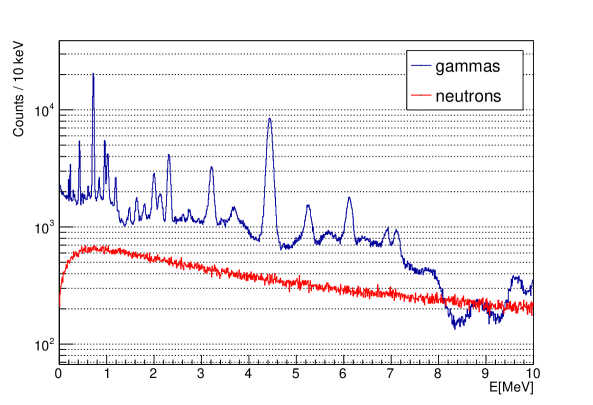
High-rate readout and digitization of data from accelerator experiments are now becoming commonplace. The High-Luminosity LHC project aims to increase its instantaneous luminosity by a factor of five beyond the original design value to and the annual integrated luminosity to which is a factor of ten from the original design value [1]. Consequently, the detectors in LHC are also upgrading the readout electronics to match the increase in luminosity [2, 3, 4]. The intensity frontier experiments, e.g. Belle II [5], Mu2e [6], Muon g-2 [7] and others require electronics and readout systems that can filter and process raw data at high efficiency and low dead time. For example, the Belle II detector at design luminosity is expected to deliver a raw data rate of [8] and they use advanced triggering schemes to reduce this to below . The Mu2e experiment is expecting an average incoming data rate of and uses triggering to reject uninteresting data. The Muon g-2 experiment has an incoming data rate of [9] and uses GPUs to pre-select pulses before processing by the DAQ. Accelerators are used not only in basic research experiments, but also in applications such as proton radiotherapy. There, large rate capability is also a key factor as the statistics is strictly limited by the maximum allowable radiation dose. Secondary radiation emitted during proton radiotherapy such as prompt gammas can be used for proton range monitoring. Some of the techniques are prompt gamma spectroscopy (PGS) requiring excellent energy resolution, prompt gamma timing (PGT) where timing resolution is crucial, and for prompt gamma imaging (PGI) both are essential. One of the detector types considered for the latter method is a Compton camera. Several groups, among others [10, 11, 12, 13], are developing such detectors. A Monte Carlo study with the Silicon photomultipiers and scintillating Fibers based Compton Camera (SiFi-CC) [14] estimates event rates reaching the SiFi-CC detector to be about considering PG and neutron events as shown in Figure 1. A readout system of a CC suitable for the application in proton therapy, as well as for other applications where high rates are involved, should fulfill the following criteria:
-
i.
Short dead time (of the order of or smaller).
-
ii.
Activity in one channel not causing any dead time in the other channels, allowing for independent processing.
-
iii.
Programmable trigger logic (channel-to-channel coincidences).
-
iv.
Scalability (up to ) channels).
In this study, several readout systems fulfilling these criteria at least partially were compared by means of their dead time, efficiency, energy- and coincidence timing resolutions. Their additional features were also discussed.
2 Readout systems
The overview of SiPM readout systems reported in 2012 [15] covered mostly ASICs in an early development phase, and not available off-the-shelf. However, recent progress in the field resulted in many different readout systems that can be used for SiPM-based detectors, e.g. calorimeters, scintillation fiber trackers, and Compton cameras. The requirements for such a system suitable for operation in a high-rate environment are low dead time and adequate dynamic range capable of measuring energy deposits. For PGI, the dynamic range should extend up to . We examined five readout systems, among which four are scalable and one was used as a reference. The five systems are chosen based on ease of procurement and measurement readiness. This includes documentation and access to their designers. These systems also pass early screening by meeting high rate operational requirements which can be quickly discerned from their data sheets or designers. Some of the tested systems provide pulse digitization per channel, which proves useful in decreasing the overall dead time. Individual systems are presented in detail in the following sections, and their main properties are summarized in Table 1.
| System | Type | Channel # | ADC [bit] | Max power/ | Input signal | Price per |
| per unit | channel [mW] | polarity | channel [EUR] | |||
| DT5742 | ASIC | 8 | 12 | 140 | +/- | - |
| TwinPeaks+TRB5sc | Board | 16 | 8 | <100 | +/- | 57 |
| A5202 | ASIC | 64 | 13 | 141 | + | 70 |
| KLauS6b | ASIC | 36 | 10, 12 | 3.6 | + | 20 |
| TOFPET2c | ASIC | 64 | 10 | 5 | + | 17 |
2.1 DT5742 - CAEN Desktop Digitizer
The CAEN Desktop Digitizer is part of a family of stand-alone instruments housing a high-speed multichannel flash 12-bit ADC with local memory and FPGA for real-time data processing. The digitizer is based on the Switched Capacitor DT5742 [16] chip. The DT5742 is a waveform sampler using a series of 1024 capacitors (analog memory) in which the analog input signal is continuously sampled circularly. The sampling frequency is by default and with options for , , and . In this study, the digitizer operates with . In the desktop form factor, it is a convenient tool with acquisition software that can be operated on Linux. It enables full waveform analysis of the registered pulses, enabling insights into the noise and pile-up issues. An earlier study of the DT5742 performance has been conducted in [17]. However, the system has limited possibilities of scaling up, so it is included in the comparison as a reference only.
2.2 TwinPeaks+TRB5sc
TwinPeaks is a custom analog add-on board designed for the DESPEC experiment at GSI/FAIR to facilitate fast-timing measurements of photo-multiplier tube pulses from the FAst TIMing Array detector setup (FATIMA [18]). In this study, the TwinPeaks add-on board [19] is connected to the front-end readout board TRB5sc [20] instead of originally to the TAMEX4 [21] board. We only have access to the TRB5sc, but both are designed by the Experimentelektronik (EEL) group at GSI/FAIR Darmstadt and could interface with TwinPeaks without further modifications. Multiple TwinPeaks+TRB5sc can be linked to a single TRB3 [22] motherboard, which incorporates a trigger system capable of sending a timing signal to all connected boards, collects data registered by them and transmits the data to the event building software. A single TwinPeaks board accommodates up to 16 analog inputs while the TRB5sc provides precise time measurement and TrbNet connectivity – an interconnection protocol between the members of the TRB hardware family. Various scale systems can be constructed in a tree-like architecture with one master module and multiple hubs to which many TRB5scs with TwinPeaks addons can be connected. TRB3 Together with TRB5sc and TwinPeaks create an FPGA-based system for SiPM readout. The energy spectrum as registered by the detector is directly converted into a pulse width spectrum, thus eliminating the need for a sampling ADC and digital waveform processing. Consequently, the energy information can be recorded by a TDC up to after the arrival of the pulse. The system is mature but only a limited number of boards are available for use in the DESPEC experiment. Its custom acquisition software, DABC [23] as well as the network protocol, TrbNet [24] are both required for the system to work on Linux.
2.3 A5202
The A5202 [25] is a part of a multi-board system by CAEN, designed for the readout of multichannel detectors. The unit houses two Citiroc-1A [26] chips by Weeroc, 32 channels each. It can operate in spectroscopy, counting, timing and time stamped spectroscopy modes. The spectroscopy and time stamped spectroscopy modes are the only ones with precise pulse height information, necessary for our purpose. However, as the 13-bit ADC runs serially for all channels, the dead time due to conversion with Citiroc-1A is relatively high, of about . In this study, efficiency and dynamic range measurements were performed in the spectroscopy mode, while for the remaining ones, where time information was also required, time stamped spectroscopy mode was utilized. These two modes perform very similarly, except that for the latter one, the time stamp information is also stored. The A5202 is a mature, commercially available system with accompanying software for data acquisition on Windows OS. It features tunable gain using high- (HG) or low-gain (LG) preamplifiers, the latter was used in the measurements described here. The system can be scaled up by using a concentrator board DT5215 [27], which can link up to 128 A5202 boards with a total number of 8192 channels. If DT5215 is unavailable, up to 16 A5202 can be daisy-chained. That board is then connected to a DAQ computer through Ethernet or USB 3.0. Furthermore, multiple DT5215 boards can be synchronized in order to further extend the total number of channels. All the components are parts of the FERS-5200 system [28] by CAEN Technologies Inc.
2.4 KLauS6b
The board was originally designed by a group at the Heidelberg University for CALICE Analogue Hadronic Calorimeter (AHCAL) [29] & ScECAL [30] detectors targeting low gain SiPMs of charge range between 15 to . It can also operate with four different gain modes, with the lowest one spanning the dynamic range up to . KLauS6b [31] is an auto/external-triggered, gain-configurable 36-channel ASIC fabricated in UMC CMOS technology. Analog data from the 36 channels are digitized and sent off-chip using either an I2C interface (up to ) or a faster LVDS interface, providing a 8b10b encoded data stream. The device that communicates with KLauS6b via I2C fetches data until the board is empty, and bundles all received hits into one acquisition object. KLauS6b samples the peak voltage and then converts it to digital code word by an ADC. A 10-bit or 12-bit ADC are available for one ASIC according to the purposes; in this work, we chose to work with a 10-bit ADC. The ADC block allows for conversion times in the order of with a internal system clock, not including the sampling time of typically . The system is still under development requiring an additional Raspberry Pi 4 connected to the development board and only a limited number of ASICs are available. It comes with acquisition software that works on Linux.
2.5 TOFPET2c
This is a readout and digitization 64-channel ASIC featuring low-noise and low-power for time-of-flight (TOF) measurements and other applications using SiPMs [32]. The digitization modules are present for each readout channel. The chip has quad-buffered TDCs and QDCs in each channel. The chip is part of a complete, scalable readout platform offered as an off-the-shelf solution by PETsys Electronics [33]. Up to 16 ASICs can be connected to a single front-end board [33] that has a clock frequency of resulting in a total of 1024 channels. Groups of ASICs can be easily programmed to select coincident events within a pre-set time window. A combination of using a PCIe with 3 SFP+ optical/copper connectors connecting to chains of a FEB/D and Trig&Clk boards can transmit data up to . This is a mature, commercially available product ready to be used off the shelf with acquisition software on Linux.
3 Test setups
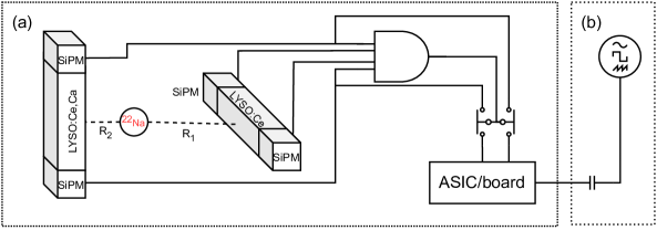
The DAQ systems were characterized with both a pulse generator and a detector setup consisting of scintillators with SiPM readout.The sensitive part of the detector setup (Figure 2a) has a form of a fiber stack made of 64 3 LYSO:Ce,Ca fibers, manufactured by Taiwan Applied Crystals. The stack has four layers and each fiber is wrapped in Al foil. For the other setup (Figure 2b), a 81160A Pulse Function Arbitrary Noise Generator [34] along with a 33 pF or 600 pF capacitor, depending on the readout system.
However, only one fiber was exploited in the tests. There is a variety of possible setup architectures in real world applications, differing in number of channels by orders of magnitude, so it is most practical to consider the smallest unit available for evaluation. This least biased method minimizes the differences due to the different hardware design decisions, e.g. ADC, buffers. With this in mind, the measured channel properties could be scaled up effectively by the reader when evaluating larger systems.
Such choice of the scintillation crystal and the wrapping material provided the best trade-off between the energy- (7.73% at ) and position () resolutions and was decided to be the optimal solution for the SiFi-CC setup [35]. On each end of the fiber stack, there was an array of 64 PM1125-WB Ketek111Ketek SiPMs are now manufactured by Broadcom SiPMs [36]. These SiPMs have 1600 microcells and a fast recovery time of . They were operated at an overvoltage of . The SiPMs and fibers are coupled with custom-made, thick Elastosil RT 604 optical pads and aligned centrally to each other, the total pitch between subsequent elements in the stack or array being . For coincidence time- and energy-resolution measurements, a 22Na source is placed between the electronic collimator and the detector system to irradiate only a segment in the middle of the test fiber in the detector, the electronic collimation procedure was as described in [37]. The 22Na source had an activity of about at the time of the measurements. The reference detector consists of a mm3 LYSO:Ce fiber with 3x3 Hamamatsu S13360-3050CS SiPMs on both sides. The coincidence trigger is constructed with the CAEN V792 module from the binary AND operation of 4 discriminated SiPM pulses from both sides of the reference detector, as well as from two ends of the fiber stack. This NIM trigger signal is then used as an input for external triggering in the various readout systems. This trigger scheme reduces the LYSO:Ce,Ca background.
4 Methodology
4.1 Dead time
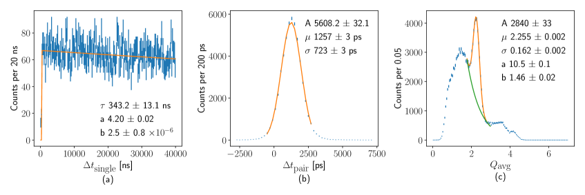
The technique used to determine the system dead time requires a single channel and a radioactive source. Besides the signals generated by the interactions of the 22Na gammas with the detector material, there was also a contribution from gammas of the LYSO:Ce,Ca intrinsic activity, which added to the occupation of the readout channels. The readout systems can register the hit times and from this obtain the time interval between subsequent hits . The distribution of time intervals between the hits is Poissonian and thus can be modelled as an exponential, whose exponent is rate-dependent. However, due to dead time, a gap near zero of the width appears, due to events missed because of digitization time, pile up and the ASIC being in BUSY mode. To quantify the dead time , a piece-wise function is fit to the distribution:
| (4.1) |
An example of such an analysis for the TOFPET2c data is shown in Figure 3a, where the determined dead time was .
4.2 Coincidence time resolution
The requirement for having a narrow coincidence time between two correlated signals is an effective way to reduce both electronic noise and the physical background. In our case, the two SiPMs located on opposite ends of a single LYSO:Ce,Ca fiber should receive hits within some time window, typically less than given the length of the crystal of . In order to mitigate the walk effect on the timing resolution, the time difference between the two SiPMs is constructed on an event sample containing only fully absorbed annihilation photons of , i.e. with energy depositions within from the mean annihilation peak energy. Figure 3b shows a sample histogram of the time difference, with the cut on energy deposit. The coincidence time resolution is then extracted as the standard deviation of the Gaussian fit to the data. The errors are calculated as , where N is the number of counts.
4.3 Energy resolution
The back-to-back production of the annihilation gamma from the decay of 22Na is a good physics filter that reduces background. Hence, the peak is useful to evaluate the energy resolution , defined as
| (4.2) |
where and are the standard deviation and the peak position of a Gaussian fitted to describe the photo peak. Energy resolution defined in Equation 4.2 incorporates several effects: SiPM parameters, scintillating fiber properties like light yield or intrinsic resolution. However, those were the same for all examined systems, as only the DAQ system was changed between measurements. Thus, such a method remains a valid comparison of DAQ systems. For our data, an exponential function and a Gaussian are chosen to locally describe the background and signal shape. An example of such an energy deposit spectrum is shown in Figure 3c as the geometric mean of the signals registered on both fiber ends, . This quantity is independent of the hit position along the fiber [38], which is not the case for individual signals and .
4.4 Efficiency
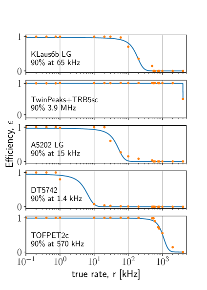
In order to determine the readout efficiency for a single channel, SiPM signals are emulated by injecting square pulses from a pulse generator passing through a capacitor into one of the test channels at increasing frequencies at a fixed amplitude . The A5202 typically digitizes data from all 64 channels serially, so for this study all but one channel are active (other channels are masked). However, it should be noted that this will produce higher efficiencies compared to operations with more channels. Spectroscopy mode measurements with the A5202 are done with low gain, LG=5. The readout efficiency, is the ratio of the measured and the true (injected) rate . The efficiency curve follows the shape of a sigmoid
| (4.3) |
where is the mid-point of the falloff and , the exponential shape parameters. The true rate at which the efficiency drops to 90% is used to evaluate the different systems.
4.5 Dynamic range
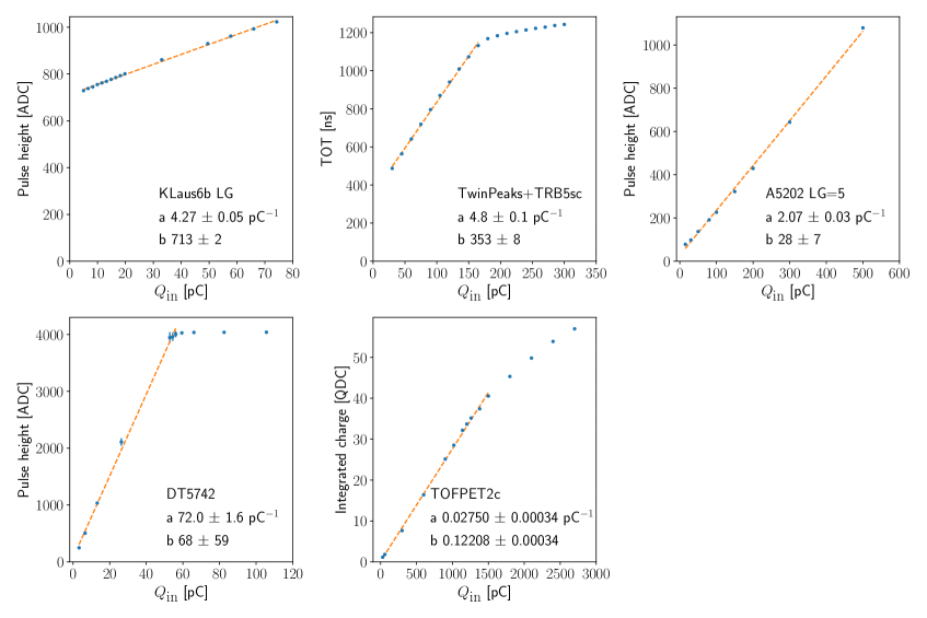
Readout systems are optimized for the signal amplitudes and charges typical for certain applications and given by energy deposits and the characteristics of the detectors under test. An RC high-pass filter is used to emulate SiPM pulses with a falling time constant of using square pulses with a peak voltage, and a capacitor with capacitance, = capacitor for TOFPET2c and TwinPeaks+TRB5sc and for KLauS6b and DT5742 realizing the total injected charge of . For A5202, an additional voltage dividing circuit was necessary to reduce the pedestal. The internal feedback capacitance of the low gain preamplifier, is set to providing an amplification factor of 10. The signal magnitude is expressed in ADC, QDC or TOT units, depending on the readout system. The signal is plotted against the injected charge, . The charge conversion factor is obtained as the slope in the linear region of this plot. This linear region determines the dynamic range of the system. The linear region is determined by first checking the linear fit slope uncertainties to not exceed 3%, otherwise the fit range is reduced. Then, a fifth order polynomial is used to find the limits where the deviation from the linear fit is more than 10%. Typically, the lower limit is at the pedestal. If no deviation from linearity was observed, the full range was considered to be the system’s dynamic range.
5 Results
The properties described in Section 4 for all the investigated readout systems are collected in Tables 2, 3 and illustrated in Figures 4, 5.
- Dead time
-
TOFPET2c has the lowest dead time of due to the quad-buffered TDCs and charge integration QDCs in each channel. KLauS6b has comparably low dead time (see Table 2) of thanks to digitization available per channel. TwinPeaks+TRB5sc does not require ADC, so it is also relatively fast, the dead time being about twice as large as the winner in this category. The A5202 simultaneously acquires and digitizes from all 64 channels when triggered, thus having about 100 times larger dead time than the winner. For the DT5742, which also features a simultaneous digitization and saves full waveforms, the measured dead time is 1000 times larger compared to KLauS6b and TOFPET2c.
- Coincidence time resolution
-
The system with the best coincidence time resolution (see Table 2) is TOFPET2c with . DT5742 performs slightly worse with , the next one is KLauS6b with , followed by A5202 and TwinPeaks+TRB5sc (3 and 10 times worse than the winner, respectively).
- Energy resolution
-
The best energy resolution (see Table 2) was obtained with TOFPET2c which is 7.2(1)%, followed by the DT5742 (20% worse), A5202 (30% worse), TwinPeaks+TRB5sc (60% worse) and finally by KLauS6b (75% worse).
- Efficiency
-
The efficiency vs rate dependence in Figure 4 and Table 3 show that the TwinPeaks+TRB5sc system could operate with full efficiency at the highest rate amongst the investigated systems, which is . This stems from the fact that TwinPeaks+TRB5sc does not perform time-costly analog-to-digital conversion. TOFPET2c ranks second in maintaining full efficiency at 7 times lower rate, followed by KLauS6b (60 times lower rate than the winner). Both A5202 and DT5742 have relatively low efficiency of the order of 1-.
- Dynamic range
-
TOFPET2c covers a significantly larger dynamic range than any other investigated system (Figure 5, Table 3, which is up to . The second largest dynamic range (4 times less than the TOFPET2c’s) is attributed to A5202. It is followed by TwinPeaks+TRB5sc (9 times less than TOFPET2c) and later by KLauS6b and DT5742 (25 times less than TOFPET2c). In case of TOFPET2c, non-linearity correction function was applied to the data, as suggested in the documentation [39]. KLauS6b and A5202 did not reach the nonlinear region as it is limited by their ADCs. The systems have very different dynamic ranges as they have been optimized for different SiPM applications.
| System | Dead time [] | Coincidence time resolution [ns] | Energy resolution [%] |
|---|---|---|---|
| KLauS6b LG | \eqmakebox[cint][r]0.352(77) | \eqmakebox[cint][r]1.53(7) | \eqmakebox[cint][r]12.4(1) |
| TwinPeaks+TRB5sc | \eqmakebox[cint][r]0.870(9) | \eqmakebox[cint][r]10.5(3) | \eqmakebox[cint][r]11.1(13) |
| A5202 LG | \eqmakebox[cint][r]44(4) | \eqmakebox[cint][r]3.0(2) | \eqmakebox[cint][r]9.4(3) |
| DT5742 | \eqmakebox[cint][r]443(97) | \eqmakebox[cint][r]1.152(1) | \eqmakebox[cint][r]8.55(4) |
| TOFPET2c | \eqmakebox[cint][r]0.343(13) | \eqmakebox[cint][r]0.723(3) | \eqmakebox[cint][r]7.2(1) |
| System | Rate at 90% efficiency [kHz] | Dynamic range [pC] | Charge conversion factor [pC-1] |
|---|---|---|---|
| KLauS6b LG | \eqmakebox[cint][r]65 | \eqmakebox[cint][r]74.25† | \eqmakebox[cint][r]4.27(5) |
| TwinPeaks+TRB5sc | \eqmakebox[cint][r]3900 | \eqmakebox[cint][r]202 | \eqmakebox[cint][r]4.8(1) |
| A5202 LG | \eqmakebox[cint][r]15 | \eqmakebox[cint][r]500† | \eqmakebox[cint][r]2.07(3) |
| DT5742 | \eqmakebox[cint][r]1.4 | \eqmakebox[cint][r]62 | \eqmakebox[cint][r]72.0(1.6) |
| TOFPET2c | \eqmakebox[cint][r]570 | \eqmakebox[cint][r]1899 | \eqmakebox[cint][r]0.025(1) |
6 Summary
Five readout systems that are either commercially available or in active development have been tested. The combined results from the tests show that TOFPET2c is the best performing system for our application given its marginally lowest dead time of , widest linearity range of up to , best coincidence time resolution of , and best energy resolution at 7.2(1)%. Additional benefits of TOFPET2c are ease of electronics configuration, lowest price per channel of all the compared systems (see Table 1) and a fully operational, bundled acquisition software. It should be noted that even though the A5202 did not obtain competitive results in our comparison apart from the second-best dynamic range, it is well suited for measurements requiring excellent photopeak separation at low intensities and not too high rates. Moreover, the channel-to-channel coincidence can be programmed in any way needed, providing a vast reduction of background data. However, this system’s price per channel is the highest of all the compared ones. With KLauS6b, a dead time of was obtained, making it the second-best choice for detectors demanding low dead time. This is the second most affordable system. TwinPeaks+TRB5sc can operate with the highest data throughput of all the studied systems, which makes it a suitable candidate for applications where the efficiency is crucial. It is also the only system of the scalable ones that can operate on signals of both polarities. Its price per channel is relatively high. DT5742 provides second-best time- and energy resolution. However, it has higher dead time and worse efficiency when operating at higher rates, as well as a relatively smaller dynamic range. This system is not suitable for detectors with large number of channels, but its ability to register full waveforms makes it a good choice for applications still in the detector development and troubleshooting. While TOFPET2c is the optimal system for the application in the SiFi-CC detector, each of the tested DAQ systems turned out to perform very well in at least one category, as a result of various features being prioritized by the producers. Depending on the use case, a different system can be optimal and by performing this comparison, we would like to provide a broad look on the data acquisition systems for high rate SiPM applications as well as to facilitate the choice of one.
Acknowledgements
This work was supported by the Polish National Science Centre (grant 2017/26/E/ST2/00618) and by the Jagiellonian University (MNS2021 U1U/P05/NO/03.29 and RSM U1U/W17/NO/28).
References
- [1] I. Zurbano Fernandez et al., High-Luminosity Large Hadron Collider (HL-LHC): Technical design report, .
- [2] G. Aad et al., The Phase-I trigger readout electronics upgrade of the ATLAS Liquid Argon calorimeters, JINST 17 (2022) P05024 [2202.07384].
- [3] CMS Tracker collaboration, The Upgrade of the CMS Tracker at HL-LHC, JPS Conf. Proc. 34 (2021) 010006 [2102.06074].
- [4] LHCb collaboration, The LHCb upgrade I, 2305.10515.
- [5] S. Yamada, R. Itoh, K. Nakamura, M. Nakao, S.Y. Suzuki, T. Konno et al., Data Acquisition System for the Belle II Experiment, IEEE Transactions on Nuclear Science 62 (2015) 1175.
- [6] Mu2e collaboration, Mu2e Technical Design Report, 1501.05241.
- [7] W. Gohn, Data Acquisition for the New Muon g-2 Experiment at Fermilab, Journal of Physics: Conference Series 664 (2015) 082014.
- [8] Belle II Software Group collaboration, Belle II at the Start of Data Taking, EPJ Web Conf. 214 (2019) 09004.
- [9] Muon g-2 collaboration, Muon g-2 Reconstruction and Analysis Framework for the Muon Anomalous Precession Frequency, J. Phys. Conf. Ser. 1085 (2018) 032039 [1710.07839].
- [10] V. Babiano, J. Balibrea, L. Caballero, D. Calvo, I. Ladarescu, J. Lerendegui et al., First i-TED demonstrator: A Compton imager with Dynamic Electronic Collimation, Nuclear Instruments and Methods in Physics Research Section A: Accelerators, Spectrometers, Detectors and Associated Equipment 953 (2020) 163228.
- [11] E. Muñoz, A. Ros García, M. Borja-Lloret, J. Barrio, P. Dendooven, J. Oliver et al., Proton range verification with MACACO II Compton camera enhanced by a neural network for event selection, Scientific Reports 11 (2021) 9325.
- [12] E. Draeger, D. Mackin, S. Peterson, H. Chen, S. Avery, S. Beddar et al., 3D prompt gamma imaging for proton beam range verification, Physics in Medicine and Biology 63 (2018) 035019.
- [13] A. Koide, J. Kataoka, T. Masuda, S. Mochizuki, T. Taya, K. Sueoka et al., Precision imaging of 4.4 MeV gamma rays using a 3-D position sensitive Compton camera, Scientific Reports 8 (2018) 8116.
- [14] J. Kasper, K. Rusiecka, R. Hetzel, M.K. Kozani, R. Lalik, A. Magiera et al., The SiFi-CC project – Feasibility study of a scintillation-fiber-based Compton camera for proton therapy monitoring, Physica Medica 76 (2020) 317.
- [15] C. de la Taille, Overview of SiPM readout electronics, PoS PhotoDet 2012 (2012) 026.
- [16] S. Ritt, Design and performance of the 6 GHz waveform digitizing chip DRS4, in 2008 IEEE Nuclear Science Symposium Conference Record, pp. 1512–1515, 2008, DOI.
- [17] K. Wang, S. Samaranayake and A. Estrade, Investigation of a digitizer for the plastic scintillation detectors of time-of-flight mass measurements, Nucl. Instrum. Meth. A 1027 (2022) 166050.
- [18] M. Rudigier, Z. Podolyák, P. Regan, A. Bruce, S. Lalkovski, R. Canavan et al., FATIMA — FAst TIMing array for DESPEC at FAIR, Nuclear Instruments and Methods in Physics Research Section A: Accelerators, Spectrometers, Detectors and Associated Equipment 969 (2020) 163967.
- [19] A. Banerjee, M. Wiebusch, M. Polettini, A. Mistry, H. Heggen, H. Schaffner et al., Analog front-end for FPGA-based readout electronics for scintillation detectors, Nuclear Instruments and Methods in Physics Research Section A: Accelerators, Spectrometers, Detectors and Associated Equipment 1028 (2022) 166357.
- [20] GSI, The TRB family, Oct 6th, 2023.
- [21] A. Banerjee, M. Polettini, H. Heggen, H. Schaffner, M. Wiebusch, M. Traxler et al., Ultra short nuclear lifetimes measured with fast detectors and faster electronics, in Hard X-Ray, Gamma-Ray, and Neutron Detector Physics XXII, A. Burger, S.A. Payne and M. Fiederle, eds., vol. 11494, p. 1149405, International Society for Optics and Photonics, SPIE, 2020, DOI.
- [22] A. Neiser et al., TRB3: a 264 channel high precision TDC platform and its applications, JINST 8 (2013) C12043.
- [23] J. Adamczewski-Musch, N. Kurz and S. Linev, Developments and applications of DAQ framework DABC v2, J. Phys. Conf. Ser. 664 (2015) 082027.
- [24] J. Michel, I. Fröhlich, M. Böhmer, G. Korcyl, L. Maier, M. Palka et al., The HADES trigger and readout board network (TrbNet), in 17th IEEE NPSS Real Time Conference, IEEE Nucl.Sci.Symp.Conf.Rec., p. 5750405, 2010, DOI.
- [25] CAEN, A5202/DT5202: 64-Channel Citiroc-1A Unit for FERS-5200 (Rev. 4), January 25th, 2023.
- [26] CAEN, Datasheet Citiroc-1A, December 17th, 2019.
- [27] CAEN, DS7218 – FERS-5200 rev.4, March 9th, 2022.
- [28] CAEN Technologies Inc., FERS-5200 Front-End Readout System, Oct 6th, 2023.
- [29] CALICE collaboration, The CALICE AHCAL: a highly granular SiPM-on-tile hadron calorimeter prototype, J. Phys. Conf. Ser. 2374 (2022) 012017.
- [30] CALICE collaboration, Performance of the first prototype of the CALICE scintillator strip electromagnetic calorimeter, Nucl. Instrum. Meth. A 763 (2014) 278 [1311.3761].
- [31] K. Briggl, M. Dorn, R. Hagdorn, T. Harion, H.C. Schultz-Coulon and W. Shen, KLauS: an ASIC for silicon photomultiplier readout and its application in a setup for production testing of scintillating tiles, Journal of Instrumentation 9 (2014) C02013.
- [32] A. Di Francesco, R. Bugalho, L. Oliveira, A. Rivetti, M. Rolo, J.C. Silva et al., TOFPET 2: A high-performance circuit for PET time-of-flight, Nuclear Instruments and Methods in Physics Research Section A: Accelerators, Spectrometers, Detectors and Associated Equipment 824 (2016) 194.
- [33] PETsys, SiPM Readout System, August 22th, 2023.
- [34] Keysight, 81160A Pulse Function Arbitrary Noise Generator, Oct 12th, 2023.
- [35] K. Rusiecka, The SiFi-CC detector for beam range monitoring in proton therapy – characterization of components and a prototype detector module, 2023.
- [36] Broadcom, Single Silicon Photo Multiplier, WB-type, 25 SPAD pitch, 4, 2021.
- [37] P. Anfre, C. Dujardin, J.-M. Fourmigue, B. Hautefeuille, K. Lebbou, C. Pedrini et al., Evaluation of fiber-shaped LYSO for double readout gamma photon detection, IEEE Transactions on Nuclear Science 54 (2007) 391.
- [38] L. Da-Zhi, L. Yuan-Jing, L. Jin, Q. Yue, W. Tsz-King, C. Wen-Chen et al., Energy reconstruction for long column csi(tl) crystal detector, Chinese Physics C 28 (2004) 186.
- [39] PETsys, TOFPET2 ASIC Evaluation Kit Software user guide v2023.07, October 9th, 2023.