SCALER: Versatile Multi-Limbed Robot for Free-Climbing in Extreme Terrains
Abstract
This paper presents SCALER, a versatile free-climbing multi-limbed robot that is designed to achieve tightly coupled simultaneous locomotion and dexterous grasping. Although existing quadruped-limbed robots have shown impressive dexterous skills such as object manipulation, it is essential to balance power-intensive locomotion and dexterous grasping capabilities. We design a torso linkage and a parallel-serial limb to meet such conflicting skills that pose unique challenges in the hardware designs. SCALER employs underactuated two-fingered GOAT grippers that can mechanically adapt and offer modes of grasping, enabling SCALER to traverse extreme terrains with multi-modal grasping strategies. We study the whole-body approach, where SCALER uses its body and limbs to generate additional forces for stable grasping with environments, further enhancing versatility. Furthermore, we improve the GOAT gripper actuation speed to realize more dynamic climbing in a closed-loop control fashion. With these proposed technologies, SCALER can traverse vertical, overhang, upside-down, slippery terrains, and bouldering walls with non-convex-shaped climbing holds under the Earth’s gravity.
Index Terms:
Climbing Robots, Grippers and Other End-Effectors, Legged Robots, Mechanism Design.![[Uncaptioned image]](/html/2312.04856/assets/x1.png)
I INTRODUCTION
The field of legged robotics set the stage for applications such as search and rescue, delivery, and even extraterrestrial exploration [1]. They have shown versatility and maneuverability in locomotion [2] and have demonstrated contact-rich tasks such as object manipulation with their own body [3]. Limbed robots have further showcased grasping, using collective legs [4], utilizing a dedicated arm [5], or employing grasping end-effectors [6]. The simultaneous interaction between locomotion and grasping, called loco-grasping, allows them to execute tasks such as carrying objects, using tools, or traversing challenging terrains [7]. However, current locomotive robots are not yet sufficient to convey one of the extreme cases of loco-grasping, which is free-climbing [8], and it is essential for multi-limbed robots to facilitate even more versatile traversability over buildings, construction sites, or caves, etc. This includes the robots traversing over not only the continuous terrains defined in Fig. 2 but also discrete environments in Fig. 2b and directionally continuous in Fig. 2c.

However, achieving free-climbing raises substantial challenges. This domain mandates both various climbing techniques and grasping adaptability as demonstrated in Fig. 1. Climbers have to consider foot placements and body stability [9], particularly in a discrete terrain environment such as in Fig. 2b. This imposes strict loco-grasping requirements; failure in either locomotion or grasping can result in a fall and task failure. Hence, free-climbing robots must consider closely coupled grasping and locomotion designs as illustrated in Fig. 3.
For tackling complex and cluttered terrains, performing multi-modal grasping becomes essential to improve climbing feasibility and stability. Multi-modal grasping is a cornerstone technique in human climbing to utilize various types of grips based on climbing holds [10]. Different grasping modes such as pinch, envelop, crimp, and pocket are strategically deployed to optimize grip or to conquer terrains that would be otherwise difficult or impossible to travel [11], [10]. Whole-body approaches, such as the sidepull grasping technique [10], add a new set of potential in climbing as they embrace the entire body and limbs to enhance grasping feasibility in scenarios where holds are infeasible to grasp stably with one gripper. Therefore, free-climbing tasks must involve successful approaches and stable grips by actively switching among various grasping modes, depending on the environmental context and climbing requirement.
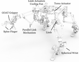
While existing platforms have paved the way for loco-grasping, there is still a gap in the strict loco-grasping and multi-modal ability in free-climbing. To address these challenges, we introduce SCALER: Spine-enhanced Climbing Autonomous Limbed Exploration Robot — a versatile quadruped-limbed free-climber, and loco-grasping research platform as shown in Fig. 1. SCALER is designed to traverse a range of extreme surfaces, from flat terrains to vertical walls and overhangs, all under Earth’s gravity. SCALER can also adeptly cross through obstacles using multi-modal and whole-body approaches with our underactuated grippers and unique C-shaped fingertip designs proposed.
Our contributions are summarized as follows:
-
1.
SCALER’s Mechanisms: We propose SCALER torso and limb mechanisms for strictly coupled loco-grasping free-climbing. SCALER realizes versatile capabilities of traversing on the ground, vertical walls, overhangs, and ceilings with payload under the Earth’s gravity.
-
2.
Underactuated GOAT Grippers: We employ an improved mechanically adaptive GOAT gripper with spine contact tips.
-
3.
Hardware Validation: We validate the SCALER free-climber platform with the spine GOAT grippers in hardware experiments.
This paper extends our previous work [12] by introducing additional contributions related to dynamic locomotion and versatile climbing strategies, thereby advancing state-of-the-art robotic free-climbing.
-
1.
Dynamic Climbing and Gait: We assess SCALER’s capabilities in trot gait during climbing with closed-loop control fashion and untethered operation. We introduce a modified trot gait to actively utilize limb compliance and its model to enhance traversability.
-
2.
Pneumatically Actuated GOAT grippers: We introduce the pneumatic GOAT grippers that enable SCALER to grasp and climb a slippery terrain dynamically.
-
3.
Multi-Modal Grasping with C-shaped Finger GOAT grippers: We propose C-shaped fingers that can realize up to modes of grasping with SCALER’s dexterity. This capability lets SCALER apply versatile strategies, such as a whole-body approach to overcome otherwise infeasible to climb scenarios.
-
4.
Hardware Validation: We validate SCALER dynamic gait and multi-modality in hardware experiments.

To the best of our knowledge, SCALER is the first robot to demonstrate a versatile suite of free-climbing abilities under Earth’s gravity and using more than two modes of grasping in climbing. SCALER achieves this by combining SCALER’s mechanical design and the GOAT grippers. Our approach makes SCALER a pioneering reference for future developments in robotic loco-grasping problems and free-climbing.
II Related Works
In this section, we review the current state-of-the-art approaches in the legged and climbing robots as well as climbing end-effector designs as follows.
-
1.
Quadruped robots torso and limb mechanisms
-
2.
Existing climbing robots and their approaches
-
3.
Climbing robot contact mechanisms
II-A Quadruped Architecture
II-A1 Torso Mechanisms
Torso mechanisms based on animal spines have been analyzed and validated for ground and climbing robots. Cheetah spine motions are implemented to improve the efficiency of the locomotion by adding compliance in the body [13]. A translational degree of freedom (DoF) in the torso has demonstrated effectiveness in steering motions [14]. Inchworm gait that extends and bends the body sequentially is mimicked to allow a small soft robot to climb up on a pole [15]. The gecko in-plane bending movement is replicated in Slalom [16], which has reduced energy consumption in climbing by half compared to the rigid body on slope, equivalent to half of the Earth’s gravity. We introduce a new torso mechanism inspired by a human stretching motion when trying to reach a high object. This helps SCALER to climb in more restricted and contact-rich environments.
II-A2 Leg Mechanisms
The latest quadruped robot technology utilizes quasi-direct drive torque actuators, such as those found in the MIT Cheetah [13], or series elastic actuators, such as those used in ANYmal [2]. While near-direct drive technology has proven successful on flat surfaces, it is not the most efficient option for climbing, requiring continuous and intense power throughout the operation. One key difference between climbing and locomotion is that the robot must fight against gravity. Thus, the leg design sustains both normal and shear forces under various gravity directions to support the robot’s weight [17].
LEMUR is specialized for climbing under reduced gravity environments, which sacrifices locomotion speed and dynamic motion capability in exchange for rich continuous and holding torque provided by non-backdrivable gear ratio servo motors [18]. HubRobo has demonstrated bouldering free-climbing under G using relatively high-gear ratio DC servo motors in serial [1, 19]. Parallel five-bar linkage mechanism-based legs used in Minitaur [20] and Doggo [21] are both competent in dynamic motion and have high output force because two actuators’ output power is linked to one. These mechanisms have minimal inertia since the heavy actuator components are in the body. Bobcat [22] optimized the Minitaur link design specifically for climbing, demonstrating dynamic climbing on a wire mesh. However, parallel linkage mechanisms increase complexity. When one robot needs to locomote on the ground, climb vertically, run, and grasp objects dexterously, it is crucial to balance power density, speed, mechanical efficiency, and workspace simultaneously.
II-B Climbing Robotics
Both wheeled [23] and linkage mechanism-based legged climbing robots [24] have successfully demonstrated climbing capabilities with spine-enhanced contacts for rock and concrete or with dry adhesive for clean flat surfaces, such as windows [25]. Soft robotics inspired by inchworm [15], or octopus [26] have replicated unique locomotion and grasping on a small scale. A cable climber is intended for suspension bridge visual inspection [27]. While these robots have shown promising vertical climbing abilities, they employ fixed locomotion methods, making them unsuitable for versatile applications such as traversing complex and cluttered environments. In contrast, SCALER is designed to embrace its loco-grasping capability, allowing for versatile traversability.
LEMUR is a high DoF quadruped-limbed robot for future space exploration missions [18]. HubRobo [1, 19] has reduced the hold grasping problem by employing a spine gripper that can passively grip a hold under Mars’s gravity. However, neither can demonstrate free-climbing under the Earth’s gravity.
Dynamic climbing necessitates robots with balanced holding torque and speed and end-effectors capable of rapid and reliable contact transitions [17]. RiSE [24] and Bobcat [22] can dynamically run on a vertical wall with spine craw on rough concrete and a mesh surface, respectively. Marvel [17] has an electromagnetic foot that can climb and conduct dynamic gait on ferrous surfaces. However, these implicit and adhesive end effectors cannot consider dexterous contacts that are essential in the loco-grasping domain. SCALER focuses on dexterous and loco-grasping in climbing, which is necessary to traverse discrete and cluttered environments. SCALER uses pneumatically actuated grippers for dynamic climbing.
II-C Climbing Contact Mechanisms
Grippers for climbing can be categorized based on the type of grasping mechanisms they employ, such as implicit adhesive methods or explicit grasping with fingers.
II-C1 Adhesive Contact
For smooth surfaces, magnetic [17], [28] or suction-based [29, 30] end effectors, dry adhesive toes such as a gecko gripper [25], and Ethylene Propylene Diene Monomer, (EPDM) Rubber [16] are viable options for climbing robots. LEMUR B [18] and Capuchin [31] have demonstrated bouldering wall climbing with high-friction rubber-wrapped end-effector hooks, which let them hang onto the holds. The pure frictional force is sufficient when a robot climbs between two walls [32]. For concrete, non-magnetic rough surfaces or loose cloth, spine-enhanced feet are desirable, such as in Spinybot II [33], CLASH [34], or the SiLVIA two-wall climber [35]. Spines or needles can get inserted into microcavities of rocky surfaces [1, 19]. With an array of spines, the gripper can grasp both concave and convex shapes while collecting the environment geometries [36]. These implicit and adhesive types of contacts can reduce the loco-grasping problem in climbing tasks into just locomotion as long as they can stick to an environment.
II-C2 Finger Grasping Contact
Two-fingered grippers have been utilized in climbing robotics such as ROMA I [11], which traverses truss structures, and Climbot [6], designed for vertical pole climbing and manipulation tasks. Humanoid robots have shown ladder climbing with grippers that hook or encompass the ladder step [9, 37]. Dexterous climbing in more complex and cluttered environments is explored in LEMUR and HubRobo. They consist of radially aligned micro-spines, supporting the robot weights under reduced gravity. A hand-shaped climbing gripper, SpinyHand [38], has four underactuated tendon-driven fingers that can switch between crimp and pinch grasping poses and has exhibited promising results for a human scale climbing robot.
While these works show impressive grasping results in climbing, these systems still lack versatility and multi-modality in Section III-1 that our gripper provides in SCALER. SCALER employs GOAT grippers [39], whippletree mechanism-based, passive underactuated two-fingered grippers that can mechanically adapt. Two variants of fingertips, spine and dry adhesive are used in the GOAT grippers to overcome different scenarios.
III Mechanical Design
III-1 Multi-Modal Contact
Multi-modal grasping, where more than one type of grasp can be realized based on the geometries of objects or tasks [40], is an effective method to improve the dexterity of the grippers and the range of graspable objects. Multi-modal capable grippers consist of multiple DoFs and underactuation, such as the Robotiq 3-finger adaptive gripper, which has five grasp types [41]. Although these approaches are common in gripper communities, it is rare for climbing robots to use more than two grasping modes. SpinyHand attempts to utilize multi-modality in climbing, but the integration into the quadruped climbing robot is yet to be achieved.
Furthermore, a human climber can utilize their whole body to make difficult-to-grasp holds workable. This whole-body approach [10] can apply additional force on a hand to stabilize the grasp by using the whole-body to pull it. The whole-body approach can also increase frictional force, resulting in climbing on otherwise impossible terrains. Our GOAT gripper with C-shaped fingers enables -modes grasping with only a single actuation. This adaptability sets SCALER apart from existing climbing robots and lets SCALER traverse and free-climb over obstacles while grasping them.
In summary, while the field of climbing robots has made considerable progress, gaps remain in achieving highly adaptive and versatile climbing capabilities. SCALER aims to bridge this gap by introducing versatile traversability over extreme terrains, dynamic loco-grasping, and multi-modal grasping capabilities.
III-A Torso Mechanism

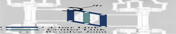

The SCALER body employs a four-bar linkage mechanism driven by one actuator, as illustrated in Fig. 5, which provides advantages in terms of workspace and forces. Conventional four-legged robots involving rigid one-body and having a torso DoF is less commonly adapted due to limited locomotion benefits than the complexity introduced. However, for climbing, we can benefit from the additional DoF on the body, making the added complexity worthwhile. SCALER’s torso includes a four-bar parallelogram linkage mechanism in Fig. 5, which enables the robot to achieve more climbing strategies. Fig. 5(a) indicates the torso’s nominal condition and components. Fig. 5(b) illustrates the 4-bar linkage torso configurations when the torso actuator is at . The center link shown in Fig. 5(a) houses an IMU, battery compartments, and a computer, which allow the center of mass to be closer to constant regardless of the torso state. This mechanism particularly benefits SCALER in two ways:
-
1.
Workspace advantages
-
2.
Force advantages
In terms of workspace advantages, this mechanism can grant the potential to shift the robot workspace on demand, as a human can stretch their arm, such as when trying to reach high objects. Furthermore, the translational torso motion can scale better to increase stride length than extending leg lengths since the limb workspace is spherical.
Regarding force advantages, the torso actuator generates a thrust force through its torque and reduces the load needed to lift the torso by half when climbing. The 2D free body diagram is in Fig. 5(c), and the thrust force is calculated as , where is the thrust force, is the torque due to the torso actuator, and the body linkage length, . If the torso actuator can generate sufficient thrust force to support half the body weight, the reaction forces and can be zero. The torso actuator in SCALER causes a maximum N thrust force in a climbing direction for SCALER, which is still significant compared to SCALER’s body and leg weight of kg.
III-B Limb
In this section, we discuss SCALER’s 6-DoF limb design and the design principles behind it as follows:
-
1.
A redundantly actuated parallel linkage leg mechanism
-
2.
The leg compliance modeling
-
3.
Spherical wrist designs
Each limb of SCALER acts as both a supporting leg and a grasping arm in climbing. Thus, the leg design must account for locomotion and grasping capabilities.
III-B1 Redundantly Actuated Parallel-Serial Link Limb
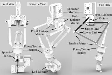
Climbing is power-intensive locomotion since the robots have to add potential energy and move against gravity. Hence, motor torque density and heat dissipation are critical. SCALER has to support and lift the system mass and withstand moments due to gravity that would otherwise pull SCALER off the wall. However, a very high-gear ratio, as seen in LEMUR [18], sacrifices motion speed significantly, whereas quasi-direct drive motors are less adequate due to less continuous torque density and overheating. SCALER limb consists of a five-bar linkage, which is serially combined with a shoulder joint and a spherical serial wrist to attain 6-DoF per leg as illustrated in Fig. 6. SCALER employs medium to high-gear ratio DC-servomotors, Dynamixel XM430-350, that are redundantly placed to achieve both functional speed and payload in climbing.
The SCALER’s five-bar parallel link mechanism utilizes two redundantly actuated joints to realize 2-DoF motions aligned in the climbing direction. The symmetric five-bar design is known to be mechanically superior in terms of proprioceptive sensitivity, force production, and thermal cost of force among serial and two different five-bar linkage leg designs in [20]. Although this choice of leg mechanism is ideal for power-intense climbing operations, the parallel mechanism suffers from several modes of singularities that can happen in the middle of the workspace, such as where both front and back passive joints shown in Fig. 6 are at the same axis. In SCALER, this condition only happens outside the regular operation (e.g., when the end effector is inside the body) since the back linkage in Fig. 6 is marginally shorter.
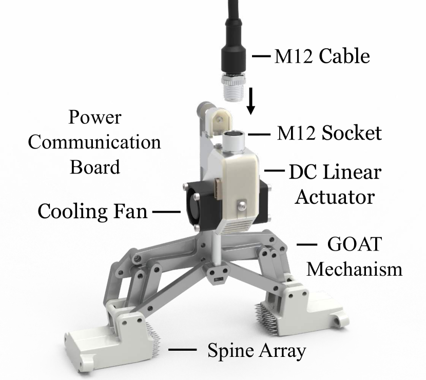
In addition to the reduced thermal cost of force in the limb design, the redundant motors on each joint distribute heat sources more evenly, keeping the motor temperature optimal and avoiding thermal throttling or damage. Such thermal considerations are vital since the power demands of free climbing are continuous rather than intermittent, such as running on the ground. Furthermore, this redundant actuation doubles the torque without changing the rotational velocity. The detachable fan above the leg cools the shoulder-leg actuators in Fig. 4.
The weight of SCALER’s limb is distributed on both ends: the body and the wrist. The intermediate links are structured with carbon fiber tubes. When the wrist and grippers are not installed, the leg consists of relatively low inertia, improving the swing leg dynamics.

| Configuration |
|
Wrist |
|
|
Applications | Fig. | Experiments Section | |||||||
|---|---|---|---|---|---|---|---|---|---|---|---|---|---|---|
| Walking | 3 | N/A | N/A | N/A | Ground Locomotion | 1b 8a | VI-A1, VI-B1 | |||||||
| \rowcolor[HTML]EFEFEF Spine Climbing | 6 | Fig. 7a | DC Linear | Spine Cell | Climbing on Rough Surfaces | 1a,c, 4 | VI-C, VI-B2, VI-D3 | |||||||
|
6 | Fig. 7b | Pneumatic |
|
|
1d | VI-A2, VI-D1, VI-D2 | |||||||
| \rowcolor[HTML]EFEFEF Bi-Manipulator | 6 | Fig. 7a | N/A | N/A | Fixed-Base Manipulation | 8b | VI-C in [42] |
III-B2 Limb Compliance Modeling
The Virtual Joint Method (VJM) modeling [43] is used to approximate limb stiffness. This model is verified through experiments in Section VI-A4. The model is based on lumped modeling and assumes joint stiffness as linear springs for small angles with a rigid link [43]. The VJM stiffness model suffices as an open-loop force estimation and control in climbing tasks as demonstrated in [32]. Our model considers the shoulder and the parallel mechanisms, and the compliance in the metal wrist and gripper linkages is negligible compared to these parts.
The stiffness matrix for SCALER’s parallel-serial leg is formulated as follows:
| (1) |
Where is a stiffness matrix in the Cartesian coordinate, are joint stiffness at the shoulder and two parallel linkage drive joints shown in Fig. 6, and is a Jacobian matrix for the leg excluding spherical joints. The condition number, indicates relative stiffness at a specific joint configuration, and it is obtained from (2):
| (2) |
and are the minimum and maximum eigenvalues of the stiffness matrix, . The stiffness map obtained from the hardware is in Section VI-A4.
III-B3 Spherical Wrist
The spherical wrist design contributes to the robot’s workspace since free-climbing requires the consideration of physically feasible trajectories and contacts [44]. SCALER employs spherical wrists as shown in Fig. 6 and Fig. 7, which have uniform end-effector offsets for all rotations and simpler inverse kinematics. The differences in proportions of the overall leg length and joint ranges for two SCALER wrist designs are shown in Fig. 7 and detailed in Table I. The wrist and leg length ratio is obtained as , where is the wrist Euclidean length from the spherical joint to the fingertip frame, in Fig. 7. is the leg Euclidean length from the leg back linkage motor joint in Fig. 6 to . While the added wrist length helps prevent wrist collisions with the environment, it also limits reachability and raises torque needs at leg joints. The wrist in Fig. 7a was used in [12], which occupied % of the limb length, whereas the wrist b) is %. However, it sacrifices the range around -axis rotations, and the wrist will be close to the environment, which can cause a collision when grasping.
III-C Modularity
SCALER design incorporates modularity, enhancing its applications for different objectives and research. This section explores various SCALER configurations and modules.
III-C1 SCALER Configurations
Modularity provides both engineering benefits and additional capabilities beyond climbing, as shown in Fig. 8). Primary SCALER configurations are listed in Table II. SCALER’s climbing configurations include four 6-DoF limbs and a 1-DoF torso, resulting in 25-DoF. Each limb includes a two-fingered underactuated 2-DoF gripper driven by one actuator, as detailed in Section IV.
The walking configuration in Fig. 8a has 3-DoF per leg by replacing the spherical wrist with a flexible semi-spherical foot cover to protect the force/torque (F/T) sensor. The walking format benefits from the minimal inertia design of SCALER’s parallel linkage leg, as most of the limb inertia is from the wrists and the GOAT grippers. A bimanual manipulator configuration uses two SCALER limbs attached on a fixed base as shown in Fig. 8b and is experimented with in [42].
III-C2 Untethered Operation Modules
For untethered operations, SCALER is equipped with additional computing and power modules. The PC and battery can be latched on the top and bottom of the center link in Fig. 5, respectively.
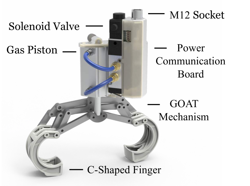
A custom-housed Jetson Orin unit weighing kg is employed for onboard vision and multi-depth camera processing, whereas a NUC6i5SYK unit weighing kg is used for non-GPU intensive applications. Power modules comprise a MaxAmp 4S v or mAh Li-Po battery, paired with DC-DC converters with a wireless emergency stop. Each leg features an independent power and communication distribution board. The gripper is connected via M12 cables, and the pneumatic system described in Section IV-B requires additional CO2 gas tanks with a regulator on the body.

III-D SCALER Gait
In this section, we introduce two new climbing gaits utilizing SCALER’s torso mechanism and limb compliance, respectively.
-
1.
SKATE Gait
-
2.
Modified Trot Gait
These gaits benefit SCALER by taking advantage of its mechanical intelligence.
III-D1 SKATE Gait
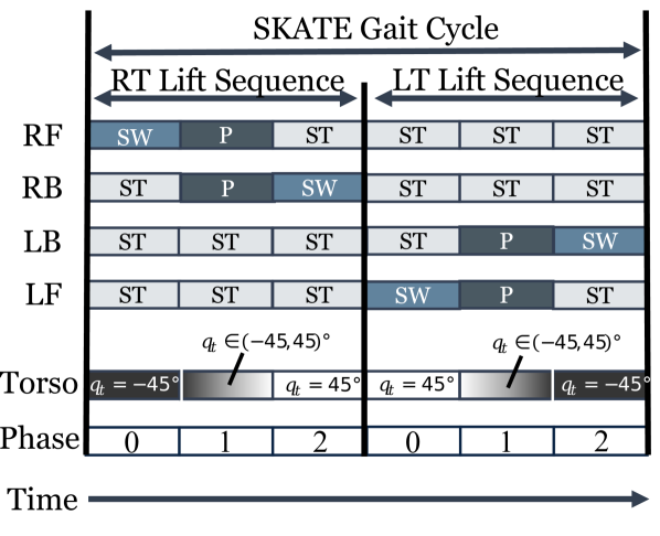
SCALER’s torso mechanism allows a unique gait called the Shifting Kinematics Adaptive Torso Extension (SKATE) gait. Our SKATE gait uses the torso actuation to maximize the advantage of the thrust force as described in Section III-A. In the SKATE gait, only half of the body moves forward for one motion sequence, such as the Right Torso (RT), and then the Left Torso (LT) moves forward. The SKATE gait schedule is shown in Fig. 10(a). The RT lift sequence uses the Right Front (RF) and the Right Back (RB) legs as follows:
-
1.
Phase 0: Swing the RF leg.
-
2.
Phase 1: Lift RT with RF, RB, and the torso actuator.
-
3.
Phase 2: Swing the RB leg.
While RT is in this lift sequence, the LT, the other side of the body, the Left Front (LF), and the Left Back (LB) legs are stationary, meaning they are not in motion. During Phase 1, the torso actuator rotates from to After Phase 2, LT enters the lift sequence, which repeats the same pattern. RT is stationary instead.
-
1.
Phase 0: Swing the LF leg.
-
2.
Phase 1: Lift LT with LF, LB, and the torso actuator.
-
3.
Phase 2: Swing the LB leg.
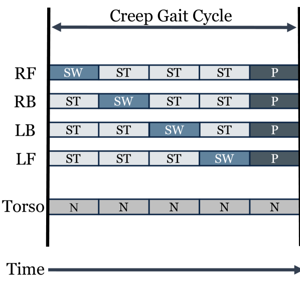
Thus, SCALER alternately lifts RT and LT over the cycle of the SKATE gait. The leg actuators can tolerate higher holding torque than in continuous motion. Furthermore, the swig legs are assisted by the thrust force from the torso actuator as illustrated in Fig. 5(c). Compared to the creep gait in Fig. 10(b), the SKATE gait has two body lift phases, and at least two legs are stationary all the time.


III-D2 Modified Trot Gait Sequence
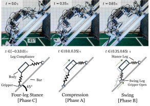
Dynamic climbing presents unique challenges, notably the sag-down effect observed in SCALER. The sag-down effect arises from a combination of gravitational forces, angular slips around the gripping points, and inherent mechanical compliance. To address this problem, we introduce a modified trot gait sequence that uses leg compliance for open-loop force control, and the gait schedule is shown in Fig. 11(a).
The modified trot gait sequence features a four-leg stance and a compression phase to counteract the sag-down effect. A four-leg stance enhances gait stability, as argued in [46]. A compression action increases the support limb’s internal energy and ground reaction force. This open-loop force control contributes to smoother transitions between the support and swing phases.
The sequence unfolds over three phases:
-
1.
Phase A: A compression action switches the support force from the RF and LB to the RB and LF leg. After this phase, the RB and LF leg assumes the primary role in bearing SCALER’s weight.
-
2.
Phase B: The RF and LB grippers open and swing forward.
-
3.
Phase C: The RF and LB gripper re-engage, resulting in a four-leg stance.
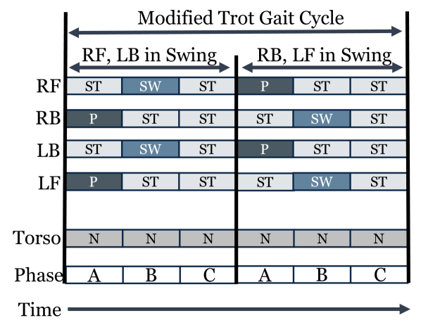
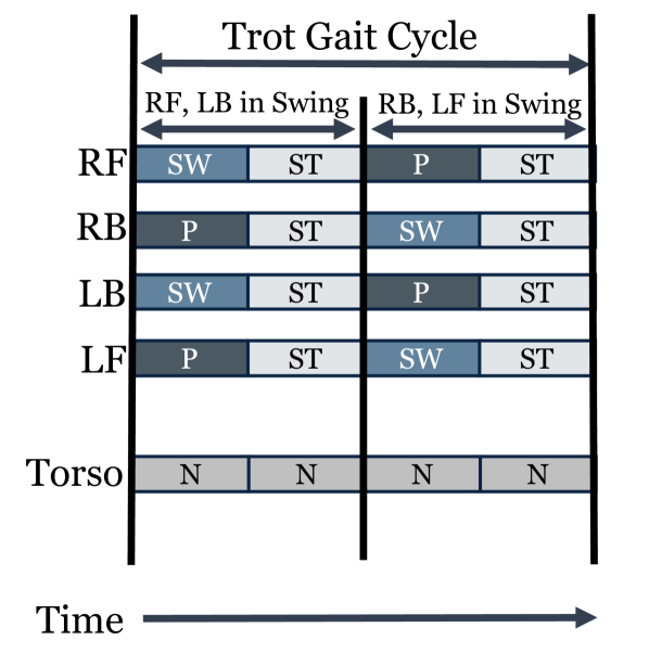
With this gait, SCALER switches support legs when all four grippers are closed in Phase A. Compared to a trot gait with a 4-leg stance presented in Fig. 11(b), at least two legs are always stationary, which eases controlling the body stability with our closed-loop controller. We demonstrate this modified trot gait in Section VI-A2 and evaluate its performance in Section VI-A3 and the model used for the associated mechanical compliance in Section VI-A4.
IV GOAT Gripper
In the following section, we present the GOAT gripper [39], a mechanically adaptable underactuated gripper. First, we outline the principles of the GOAT mechanism and its inherent capability in climbing environments. Then, we describe two distinct modules of the gripper as follows:
The spine-enhanced fingertips are adequate on rough climbing holds discussed in Section IV-C1, and the C-shaped fingertips can realize multi-modal grasping as detailed in Section IV-D, thereby illustrating their versatility in addressing diverse climbing challenges.
IV-A The GOAT Mechanism
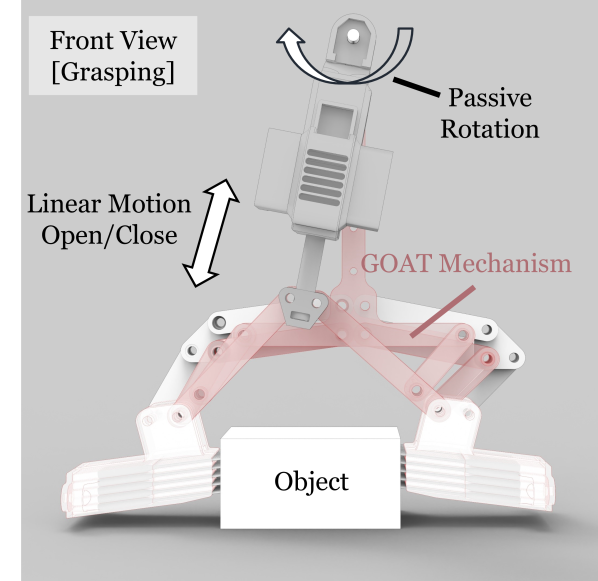
Here, we introduce the GOAT mechanism [39] visualized in Fig. 13(a), which is used in SCALER’s GOAT grippers. The GOAT mechanism is a mechanically adaptable whippletree-based underactuated rigid linkage system. Successful free-climbing in discrete environments requires grasping holds despite various uncertainties. The GOAT gripper can help mitigate these challenges by compensating for end-effector configuration errors with one passive DoF. Traditional parallel jaw grippers have only 1-DoF, either open or closed, and grasp objects at their central axis. The GOAT’s extra underactuation allows the GOAT gripper to adapt passively and grasp off-center objects as is, as illustrated in Fig. 13(a). This adaptability is further extended to realize multiple modes of grasping, as detailed in Section IV-D.
During the design process of the GOAT gripper, the linkage lengths, workspace, and forces are parametrically optimized as discussed in [39]. The design process considered bouldering hold sizes and the force requirements necessary to support SCALER’s weight. This formed a multi-objective nonlinear optimization problem with two objectives: two fingertips with active and passive DoF motion ranges and fingertip normal forces based on static force equilibrium. These two objectives are in a trade-off relationship, and the optimized GOAT mechanism is evaluated with bouldering holds in [39].
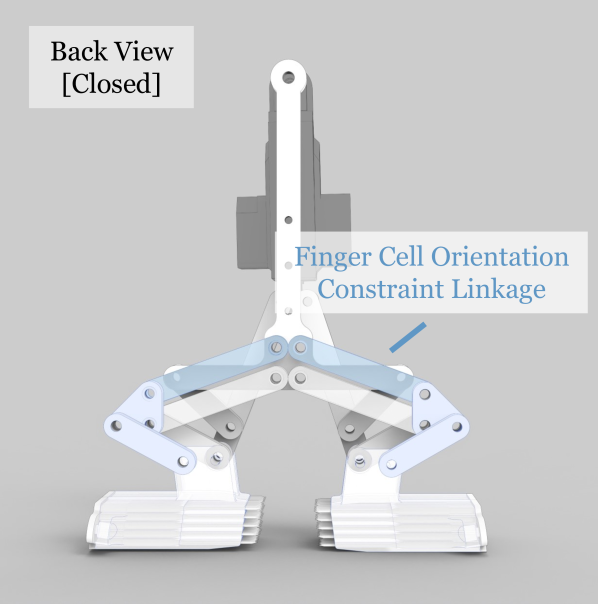
In contrast to the design in [39], the external four-bar linkages constrain the orientations of the fingertip to remain parallel to each other, as shown in Fig. 13(b). This constraint ensures that the fingertip contact surface, such as the angle of the spine needles, remains constant regardless of the GOAT gripper’s kinematics configurations.
IV-B Gripper Actuation
We discuss our following two actuators used in our GOAT gripper:
The DC linear actuators rendered in Fig. 12(a), while lightweight and capable of closed-loop controls, operate at a slower speed. When used with the GOAT gripper, they open and close fully at a frequency of Hz with no load. In contrast, the high-pressure pneumatic actuator shown in Fig. 12(b) can run at a frequency of Hz. The pneumatic actuator is % heavier than the DC linear motor. This does not count toward SCALER’s body payload since it acts at the end-effector. Additional gas tanks and regulators are installed on the SCALER’s body.
The DC linear actuator can generate N continuous force output and the maximum N. The pneumatic actuator can operate at the maximum MPa with the continuous N force output. Its nominal operation force is N at MPa. Consequently, the gas pneumatic-driven GOAT gripper allows SCALER to climb faster, albeit at the cost of SCALER’s payload capacities due to additional components required.
IV-C GOAT Gripper Fingertip
GOAT grippers have three types of fingers depending on the surface and applications as follows:
-
1.
Spring-Loaded Spine Enhanced Fingers
-
2.
C-shaped Dry Adhesive Enhanced Fingers
The spine tips are for rough and rocky surfaces, whereas the dry adhesive can grasp slippery terrains.
IV-C1 Spring-Loaded Spine-Enhanced Fingers
The spring-loaded spine-enhanced finger GOAT gripper is rendered in Fig. 12(a). Our spring-loaded spine cell design is based on the concept presented in [47]. Each cell comprises fifty spines, each with a diameter of mm, each loaded by a mN/mm spring. The cell surface is slanted so that the spines approach at an optimal angle against flat object surfaces. Optionally, strain gauges can measure normal-axis grasping force at the fingertip, as demonstrated in [48]. The spine tips are more appropriate on rough textures such as rock, concrete, and bouldering holds that have microcavities on their surface.
IV-C2 C-shaped Dry Adhesive Enhanced Fingers
The C-shaped finger GOAT gripper shown in Fig. 12(b) can realize several different grasping modes by utilizing both actuated and underactuated DoFs, and the robot’s whole body. Because of finger geometries, the C-shaped finger has elastomer dry adhesive applied on both the inside and outside C sections instead of spine arrays. The dry adhesive increases the friction coefficient, and thus, the robot can climb even slippery terrains.
IV-D Multi-modal Grasping with C-shaped Fingers
IV-D1 GOAT Gripper Multi-Modality
Diverse grasping modes allow robots to use an appropriate type of grasping method for different geometries. Paired with C-shaped fingers and one underactuated DoF, SCALER can embrace the potential for versatile multi-modal grasp in climbing. The list of these modes and applicable objects is listed in Table III.
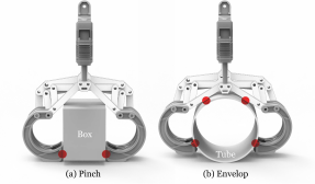
Pinch and envelope grasps [41] are standard in two-fingered grippers rendered in Fig. 14a,b, respectively. The pinch grasp relies on friction, while the envelope encompasses an object mechanically. The C-shaped fingered GOAT gripper allows the off-axis pinch as well.
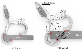
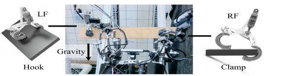
The plate clamp, as visualized in 15a, resembles a crimp grip, and it allows the GOAT gripper to clamp down thin plates with the C-shaped fingers and underactuation. When encountering plates with a thickness beyond the C-shaped opening, SCALER can embrace a whole-body approach, sidepull, to stabilize the grasping instead. This tactic is common for a human climber to overcome bouldering holds that cannot be grasped [10]. Using SCALER’s whole-body, SCALER can pull the gripper to the side in Fig. 15b against the moment generated by the two fingertip forces.
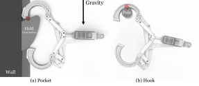
Pocket grasp [10], and hook [11] allow SCALER to hook onto narrow structures, such as poles and wire, as shown in Fig. 16a,b, respectively. This method is reliable as it does not necessarily depend on friction. Demonstrations of these grasping capabilities are explored in the SCALER hardware experiments, such as Scetion VI-D1 and VI-D2.
IV-D2 Sidepull Force Model
The fingertip’s normal force will generate a moment when grasping a thick plate. Hence, the sidepull force must cause at least a greater moment than it, which is modeled in (3) and visualized in Fig. 15b.
| (3) |
Here, is a moment acting due to the fingertip force vectors denoted as . is the Euclidean distance between two , . is the perpendicular distance from the center of grasp and the gripper frame, is the sidepull force, and is the gripper angle with respect to the plate grasping. The model and sidepull whole-body technique are experimented with in Section VI-D2.
| Mode | Objects | Figure | ||
|---|---|---|---|---|
| Pinch | General Items in the range | 14a | ||
| \rowcolor[HTML]EFEFEF Pinch Off-axis | Items placed off-centered | 13(a) | ||
| Envelop | Cylindrical items | 14b | ||
| \rowcolor[HTML]EFEFEF Plate Clamp |
|
15a | ||
| Sidepull |
|
15b | ||
| \rowcolor[HTML]EFEFEF Pocket | Items with pocket holes larger than fingertips | 16a | ||
| Hook | Bars and pipes smaller than C-finger | 16b |
IV-E Grasping Force Controllers
The grasping force, or the normal force at each fingertip, is crucial in stable climbing. The undesired angular patch slip is prevented by adjusting the grasping force as demonstrated in [44]. Increasing grasping force can help stabilize the grasp during incipient slipping [49]. However, consistent grasping can generate excessive heat, potentially degrading the DC linear actuator over time; hence, grasping force control is necessary. The DC linear actuated GOAT gripper includes the three controllers as follows. The pneumatic actuator only has an on-off control.
-
•
Position control
-
•
Current-based force control
-
•
Stiffness model-based force control
The MightyZap DC linear actuator by IR Robot used in the gripper, features a position control and current-based force control. Using the gripper inverse kinematics, the linear actuator joint position is obtained for the fingertip position control. The input force applied to the GOAT mechanism can be converted into output fingertip force using static equilibrium, as the linear actuator is relatively slow. Stiffness model data is collected using a load cell while grasping different object sizes in [48]. The spine GOAT gripper maximum withstanding force has been linearly modeled in relation to the object surface slope using Gaussian process regression as outlined in [39]. The model is stochastic due to the spine tip effects [47].
V SCALER Software
In this section, we discuss SCALER’s software, sensors, and control frameworks in Fig. 17.
V-A Sensor-Actuator Interface and Frequencies
SCALER is equipped with various sensors: four F/T sensors on the wrists, a localization camera, a body IMU sensor, tactile sensors, Dynamixel actuator encoders, and sensors on the GOAT gripper. A dedicated Input/Output thread manages each set of sensors. The system’s sensors and actuators operate at their respective maximum frequencies, which are sufficiently higher than the frequencies of controller modules. The Bota Rokubi F/T sensors operate at Hz, the Intel RealSense T265 localization camera is set to Hz, the Microstrain 3DM-GX4-25 IMU runs at Hz, and The Gelsight Mini tactile sensors at FPS. Meanwhile, the Dynamixel XM430 communicates at a frequency of Hz via RS-485 and a USB serial bus. We have implemented a joint position control with joint velocity as a control input, which allows us to customize the joint motion profile for more dynamic motions.
Each limb features a redundant actuator communication chain for robustness and safety. The wrist and gripper actuators are connected to the shoulder power and communication distribution board via a M12 cable.
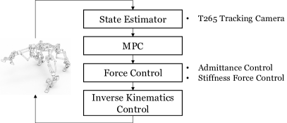
V-B Force Admittance Control Framework
Admittance control is employed to track desired operational space force profiles in contact-rich tasks. Wrench or force tracking is essential to sustain dynamic stability and mitigate disturbance due to premature or unintended contacts. The control framework (4) extends the formulation in [50] to accommodate the wrench reference trajectories. Each leg has an independent admittance controller.
| (4) |
Here, , , and are the user-defined diagonal admittance control gain in , . and are the end effector 3D pose and its first and second derivative. is a 3D wrench vector. and are the desired wrench and pose. The control input is the double integral of . The is estimated with the F/T sensors and the method described in [48]. The and are measurements.
Due to gear backlash, the controller struggles to track rapidly changing force profiles [48]. This control bandwidth suffices for low-speed tasks such as quasi-static climbing that experience less frequent force reference changes. The admittance controller experiments are shown in [44] and [48].
V-C Model Predictive Control
Model Predictive Controller (MPC) disturbance rejection becomes more important when SCALER conducts dynamic motion with the pneumatic actuators since the gripper induces disruption. Our MPC employs linearized discrete-time dynamics in (5), which is adapted from [51]. and are the discrete-time linearized dynamics models at a discrete time, , is the robot trunk pose and velocity, and is a ground reaction force.
| (5) |
However, the gravity vector may change depending on the climbing environment, such as a slope, vertical, overhang, or ceiling, though is still a constant given a known slope. Hence, the modified is presented in (6), where is the wall rotation matrix in with respect to the Earth’s local tangent plane frame, is a gravitational acceleration constant, and is a zero matrix.
| (6) |
Since SCALER has high-gear ratio servos, SCALER uses as control inputs instead of as in [51]. With the admittance control, is converted and used as a reference as demonstrated in [48]. However, the MPC performance is bounded by the lower control bandwidth admittance controller. The MPC runs at Hz, and the state estimators run sufficiently faster.
VI Hardware Experiment
In this section, the performance of SCALER in various climbing and ground locomotion tasks is evaluated to address the following questions:
-
1.
SCALER’s capabilities for dynamic locomotion on the ground and dynamic climbing on the slope.
-
2.
Its power-intense motion capacities, e.g., payload, in each of these scenarios.
-
3.
Performance in inverted environments (e.g., ceiling), including slippery terrains.
-
4.
Multi-modal and whole-body grasping in free-climbing.
During these experiments, an off-board computer and external power supply were used to operate SCALER as precautionary measures. The fully untethered operation is covered in Section VI-A5.
VI-A Dynamic Locomotion
VI-A1 Trot Gait on the Ground
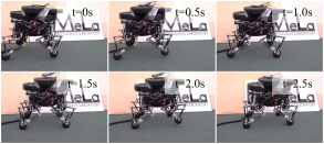
First, we evaluate SCALER’s dynamic locomotion capability on the ground. SCALER trotted at m/s, or normalized body velocity of s-1, normalized based on the body length. This trot velocity was recorded based on the video frame. SCALER 3-DoF walking configuration demonstrated that SCALER can trot at a decent velocity compared to recent ground quadruped robots.
VI-A2 Dynamic Climbing with Modified Trot Gait
In this experiment, we demonstrate SCALER’s dynamic climbing capability using the proposed modified trot gait on the hardware. Dynamic climbing introduces a new set of challenges for SCALER, as mentioned in Section III-D2. GOAT grippers should be able to change the grasping states rapidly, and SCALER must resist disturbances from the gripper, gravitational sag-down effects, support leg shifts, etc.
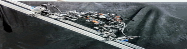
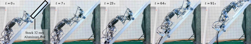
SCALER equipped with pneumatically actuated GOAT grippers performed a modified trot gait on the sloped aluminum bars, as seen in Fig. 18. This terrain is slippery and has low friction. SCALER reached m/s or a normalized velocity of s-1, while conducting a dynamic loco-grasp climbing. This was times faster than demonstrated in [12]. The fastest climbing with a DC-actuated GOAT gripper is in Section VI-D3, during which the robot was idle for % of the time because the gripper takes -second for the opening and closing cycle. This bottleneck is overcome by the pneumatic gas-actuated GOAT grippers, which take s for the cycle.
VI-A3 Efficacy in Sag-Down Mitigation with Modified Trot Gait
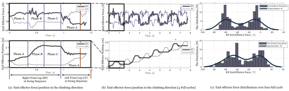
This section validates the modified trot gait’s effectiveness in reducing sag-down during dynamic climbing. Climbing direction end effector force and position were measured using F/T sensors and a T265 camera. The gait sequence and design details are in Section III-D2, and each Phase is visualized in Fig. 18. This gait is effectively an open-loop force control to switch the support forces when all four grippers are grasping. At the start (Phase C), SCALER’s LF and RF legs serve as the supporting and swinging legs, respectively. In Fig. 19a shows forces and positions in the climbing direction (i.e., the direction of the aluminum bars) for the first 4 phases, and Fig. 19b is data for 4-full cycles of the gait. Fig. 19c is the normalized force histogram over the 4-full gait cycle.
In Phase A, the RF force drops to nearly zero, while that of the LF’s doubles due to the compression action. This causes a slight position ’drop,’ which is interpreted as an ’imaginary slip.’ The T265 camera estimator assumes rigid legs where the actual limb is compliant, which detects the apparent but non-actual slip. Phase B sees RF gripper force disturbances as it swings forward. Phase C closes grippers and maintains a 4-leg stance for stability.
The distinct force/position pattern repeats over four trot gait cycles. The two peaks in Fig. 19c represent the forces during stance and swing sequences. Skewness in these peaks between RF and LF suggests influences such as the robot tilting toward RF.
In summary, the modified trot gait has achieved the intended gait design objectives, confirmed by both experimental data and an attached video showcasing SCALER’s successful climb, compared with a failed conventional trot gait case.

VI-A4 Limb Compliance Model and Force Analysis
The VJM model in Section III-B2 is calculated, and the stiffness map is in Fig. 20, which is the inverse of the stiffness condition number. The valley in the stiffness map visualizes the stiffest regions [52]. Stiffness increases when the leg is stretched and decreases when it shrinks. The joint trajectory recorded from the experiment in Section VI-A2 is plotted on the stiffness map in Fig. 20. This verifies that SCALER benefits from compliance in the leg during the modified trot gait. The stiffness of each joint was measured using a Mitutoyo HD-12 AX, which applied a force on the F/T sensors to deform the joint.
The compression force during Phase A in Section VI-A2 is estimated to be N using VJM given the commanded m pre-compression in the climbing direction. The compression force generated from the LF in Phase A in Fig. 19a is N on average. Our compliance model provides adequate stiffness estimation for the SCALER’s climbing tasks, with a % modeling error for this modified trot gait case.

VI-A5 Untethered Climbing Using Gas-Actuated Grippers with MPC
SCALER can operate fully untethered when equipped with the computing and power modules. This represents SCALER’s ability to go off-grid and climb with no range limit due to the tethering. Fig. 21a shows the SCALER climbing on a slippery slope untethered, and Fig. 21b is the corresponding trunk states from the T265 camera. A CO2 cartridge and a regulator are installed on the body for gas-actuated GOAT grippers SCALER used the modified trot gait with MPC presented in Section V-C as well.
VI-B Payload Capacity
VI-B1 Ground Trotting with Payload
To benchmark SCALER’s load capacity compared to other quadruped robots, we attached a payload of a kg weight to its belly and an kg weight on the top, corresponding to times its own weight. The trotting velocity of SCALER with the kg payload was at m/s, or a normalized velocity of s-1. This payload was the maximum SCALER can trot, but it struggled to move in a straight direction. A payload of kg yielded a speed of m/s, and SCALE was able to trot in a straight line. A normalized work capacity, defined as , where and represent normalized maximum body velocity and payload, respectively, provides a quantitative metric for SCALER’s mechanical efficiency of legged robots [53]. SCALER outperformed other robots with the normalized workload capacity of [53].
VI-B2 Vertical Wall SKATE Gait Climbing with Payload
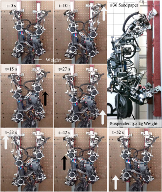
In this experiment, we evaluated SCALER’s mobility in vertical climbing with a payload. We tested SCALER on a vertical wall outfitted with a straight m wide rail covered by sandpaper to simulate rock surfaces. Each gait sequence lifted the body by m and achieved a speed of m/min while carrying a kg payload. This accounts for % of SCALER’s total weight including grippers, which amounts to an overall weight of kg. Suspended payloads pose challenges due to pendulum dynamics. The black and white arrows in Fig. 23 indicate which leg and body parts moved compared to the previous frame, respectively, using the SKATE gait schedule shown in Fig. 10(a). SCALER demonstrated vertical climbing with a payload, indicating the SCALER’s power-intensive motion and the GOAT gripper capabilities.
VI-C Inverted Environments
In inverted environments, such as overhangs and ceilings, the effectiveness of the grippers becomes pivotal. These grippers must exert sufficient contact force to counteract the gravitational pull.
VI-C1 Overhang Climbing
SCALER climbed on an overhanging wall tilted at towards the robot in Fig. 24(a). A weight of kg was suspended from indicating the direction of gravity. Gravitational force disengaged SCALER from the wall in this configuration, which helped the spine fingertips to break the contact when lifting limbs.
VI-C2 Upside-down Ceiling Walk On Rough Surfaces
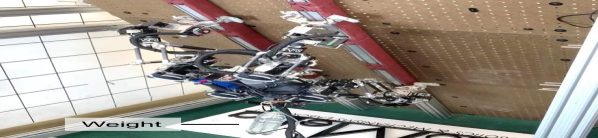
When SCALER operates in an upside-down orientation on the ceiling, SCALER uses spine fingertip GOAT grippers to latch onto a rail attached to the ceiling, as demonstrated in Fig. 1a. A weight of kg is suspended from SCALER.
The fingertip spine effects enhance the gripping effectiveness. These effects enable SCALER to maintain a stable grip on the ceiling, even when only two grippers are grasping, as shown in Fig. 24(b). Furthermore, these finger spines allow SCALER to remain attached to the ceiling or a vertical wall even when the system is powered down. This is because the spine effects can generate sufficient shear force with minimal normal force as long as the needle tips remain engaged with the surface microcavities.
VI-C3 Upside-down Ceiling Walk on Slippery Metal Surface
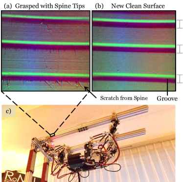

In this experiment, we evaluate the spine GOAT grippers on a slippery aluminum surface as pictured in Fig. 25a,b with Gelsight Mini tactile sensors [54]. SCALER successfully walked on a T-slotted aluminum bar upside down in Fig. 25c. The spines engaged with micro textures on the aluminum bar surface, generating enough shear force to support SCALER upside down on the slippery surface. The tactile images shown in Fig. 25a,b compare the aluminum bar surface grasped with the spine and a new unused identical aluminum bar. Fig. 25a shows that the spines caused scratches at the bottom edge of grooves. These etches indicate that the spines are anchored in the grooves to generate shear forces, whereas spines making contact on the flat aluminum surfaces do not contribute to this shear force significantly.
VI-D Multi-Modal and Discrete Terrains Free-Climbing
This section focuses on SCALER’s loco-grasp free-climbing capabilities in directionally continuous (Fig. 2c) and discrete environments (Fig. 2b).
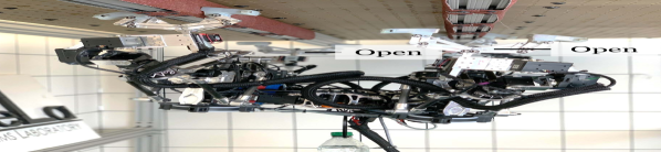
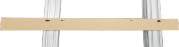
VI-D1 Climbing over Obstacles with Multi-Modal Grasping
We experiment with SCALER’s ability to overcome obstacles while climbing through multi-modal grasping. SCALER leverages the C-shaped fingered GOAT grippers to climb by grasping obstacles. An mm plate obstacle was placed across the T-slotted aluminum bar oriented at as shown in Fig. 26(a). SCALER clamps and hooks the obstacle plate from the side and top to continue climbing as captured in Fig. 26(b). This capability enhances the SCALER’s traversability since it can utilize obstacles to roam through environments instead of avoiding them. Fig. 27 shows the front view of SCALER conducting multi-modal grasping with rendering of the RF and LF grasping states. Fig. 27b,d pictures that SCALER orients and aligns the grippers to clamp and hook the plate.
The success of the multi-modal grasping method signifies SCALER’s dexterous capabilities, making it more versatile in traveling complex terrains than traditional climbing robots.

VI-D2 Whole-body Approach in Climbing
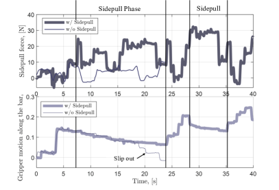
We explore SCALER’s whole-body climbing strategy for overcoming difficult-to-grasp obstacles, as displayed in Fig. 28 and 29. Fig. 30 contrasts the RF gripper’s sidepull forces and positions in the climbing direction with and without sidepulling. The whole-body approach integrates the capabilities of both GOAT grippers and SCALER.
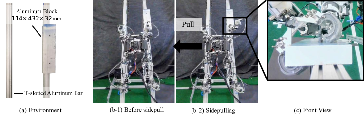
When confronted with a thick, slippery obstacle plate, as depicted in Fig. 29a, SCALER employed a side-pull technique. The plate’s dimensions made it not graspable stably for a pinch or a clamp grasp, necessitating the whole-body approach, sidepull. Fig. 29b-1 and 29b-2 visualize SCALER pushing itself to the left to sidepull the RF GOAT gripper. The close-up gripper front view in Fig. 29c resembles the sidepull rendered in Fig. 15b.
In the sidepull phase displayed in Fig. 30, SCALER applied lateral force to the RF gripper in the creep gait (Fig. 10(b)), enabling stable grasping. The minimum required sidepull force was estimated at N based on the model in Section IV-D2). Both the with/without-sidepull cases slipped at a similar rate until s since the sidepull force was insufficient. While the without-sidepull case couldn’t meet this force and slipped out by s, the with-sidepull case stabilized after reaching N. This presented that the sidepull force can stabilize the grasping, and the sidepulling force model aligns with the results. SCALER successfully traveled over the mm obstacles and returned to the aluminum bar.
This whole-body strategy enhances SCALER’s traversability further and demonstrates the symbiotic potential between the robot and its gripper in climbing.
| Robot |
|
|
|
|
|
|
|
|||||||||||||||||||
|---|---|---|---|---|---|---|---|---|---|---|---|---|---|---|---|---|---|---|---|---|---|---|---|---|---|---|
| SCALER (Walking) | 3 | |||||||||||||||||||||||||
| ANYmal | 3 | |||||||||||||||||||||||||
| Stanford Doggo [21] | 2 | N/A | N/A | |||||||||||||||||||||||
| Titan XIII | 3 | |||||||||||||||||||||||||
| SPOT | 3 | |||||||||||||||||||||||||
| Mini Cheetah | 3 | * | * | N/A |
-
•
*The value is theoretically based on the continuous force per leg. Normalized Velocity: body length divided by the body velocity. Normalized Payload: body weight divided by payload. Normalized Work Capacity: normalized speed normalized payload, a mechanical efficiency metric [53].
| Robot |
|
|
|
|
|
Gripper | Environment | ||||||||||||||
|---|---|---|---|---|---|---|---|---|---|---|---|---|---|---|---|---|---|---|---|---|---|
|
|
|
|
|
|||||||||||||||||
\rowcolor[HTML]EFEFEF
|
|
N/A |
|
|
|||||||||||||||||
|
|
|
N/A |
|
Discrete Fig. 2b | ||||||||||||||||
\rowcolor[HTML]EFEFEF
|
|
|
N/A |
|
Flat Solid/Soft Fig. 2a | ||||||||||||||||
| RiSE [24] |
|
|
Spine Array |
|
|||||||||||||||||
| \rowcolor[HTML]EFEFEF Bobcat [22] |
|
|
N/A | Spine Array |
|
||||||||||||||||
|
|
|
N/A | N/A | two-fingered Gripper |
|
|||||||||||||||
\rowcolor[HTML]EFEFEF
|
|
|
|
|
-
•
Climbing Gravity: simulated gravity used in their robot climbing tests, where is a gravitational constant. Climbing velocity: the robot’s body velocity while climbing. Normalized velocity is the climbing velocity normalized by the robot’s body length. * The body length of LEMUR is approximated to be half of the track length reported in [18]. EPDM stands for Ethylene Propylene Diene Monomer.
VI-D3 Bouldering Vertical Free-Climbing
This experiment demonstrates SCALER’s ability to climb in discrete environments, particularly on a vertical bouldering wall. GOAT grippers have to grasp bouldering holds with a non-convex shape. Conventional polymer-made bouldering holds were installed on a wall, and SCALER was operated using a predefined manual trajectory. SCALER successfully climbed up for four steps in Fig. 31, and each leg moved to the next bouldering hold at m/min or a normalized speed of min-1. The torso actuator stretched the legs occasionally to shift the workspace.
SCALER’s performance in the bouldering wall environment illustrates its potential in applications where maneuvering in discrete, unstructured environments is necessary. More discrete environment climbing with obstacles in geometric pattern holds have been demonstrated in [44].
VII Discussion and Limitation
In this section, we discuss key takeaways and limitations from our experiments. Data from SCALER hardware experiments are compiled and summarized in the tables for comprehensive analysis. Table IV contrasts the 3-DoF walking configuration of SCALER with other legged robots such as ANYmal and SPOT, revealing that SCALER achieves comparable normalized speeds. Notably, SCALER surpasses all other quadrupeds in its ability to carry a payload over twice its weight and normalized work capacity, as evidenced in [53].
Table V compares SCALER to other state-of-the-art climbing robots to SCALER regarding their operation environments, end-effector, and capabilities. SCALER has successfully shown traversability in various directions of gravity and versatile climbing performances across different climbing holds. We can distinguish climbing robots based on whether they have multi-finger grippers or not. This is a notable difference since the adhesive type of end-effectors can reduce the climbing problem down to locomotion under different gravitational force directions. Suction [30], magnetic [17], and gecko or Van der Waals force-based end-effectors generate normal forces regardless of the direction of gravity. Therefore, if such an end-effector can provide enough adhesive forces, then the robot does not need to consider dexterity or grasping explicitly.
VII-A Limitation
VII-A1 Rigidity and Compliance
Since SCALER is a loco-grasping platform, balancing conflicting requirements presents a design challenge. For instance, rigidity in joints and linkages provides the benefit of accuracy and repeatability in position-controlled manipulation under load [55], while compliance offers mechanical adaptability [37]. Such adaptability is useful for mechanically compensating for uncertainties in the system and the environment. In the modified trot gait, compliance is used as the open-loop force control.
Nonetheless, we observed failure cases in experiments due to leg compliance, especially in high-friction environments such as sandpaper. When SCALER approaches an object with a high-friction surface, it can fail to grasp the object if one of its fingers makes an undesired contact. In position control settings, the leg stiffness limits the force required to break this undesired contact unless the joint reaches its torque limit. This limitation arises because the deflection is solely due to the difference between the intended goal position and the point where the undesired contact occurs.
SCALER leg consists of three major compliance sources: parallel link mechanisms, gear backlash, and wear. The passive joints and carbon fiber tubes are respectively compliant, though the SCALER’s two redundant front linkages enhance rigidity. The SCALER’s actuators use spur gear with backlash, translating to the maximum mm offset given leg length. This uncertainty propagates through the serial shoulder and leg and the parallel mechanism non-linearly across the workspace. Over time, the gear and output shaft wear increase backlash and the task-space position control inaccuracy. The model in Section III-B2 helps us understand the characteristics of the SCALER leg compliance. Leg compliance has been accounted for in planning as demonstrated in [32] and [35].
VII-A2 Limb Dexterity
Another metric for evaluating grasping capability is the dexterous workspace. While dexterity can be improved by eliminating the end-effector offset from the spherical wrist, practical considerations such as gripper geometries and potential collisions with environments must also be accounted for. Although the variants of the SCALER wrist in Fig. 7 have sufficient joint range for our designated tasks, the workspace can be constrained by self or environmental collisions, depending on the gripper’s orientation and the position of the parallel link elbow joint. Consequently, it is important to consider potential collisions when planning trajectories along with kinematic and dynamic feasibility for all legs, fingers, and the body to ensure safe climbing.
VII-B GOAT Gripper Limitation
VII-B1 Contact State Transitions
The GOAT gripper features spine-enhanced fingers that aid in grasping by penetrating an object’s surface cavities. While the spine has shown notable performance in our experiments, the spine-enhanced fingers can also act as a barrier to gripper state transition due to their strong adherence. Additionally, the stochastic and substantial force generated by the spine-enhanced fingers, as graphed in [39], can be undesirable. When the spine fingertip contact breaks during the opening and lifting of the gripper, the internally stored energy from leg compliance is released abruptly, which can cause a non-negligible disturbance to the robot. This potentially accelerates the wear and damages the spine tips, reducing the life cycle of the finger, which is a common issue in spine grippers such as in [18].
VII-B2 Macro and Micro Scale Contacts
Although the GOAT gripper can realize various grasping types, it can only explicitly consider larger-scale contact modes. However, relatively small-scale surface feature and dynamics significantly affects the success of grasping [56]. In Fig. 25c, SCALER can walk upside-down with spine tips on metal bars. However, spine tips require a covered surface for vertical climbing, and SCALER could not climb vertically on the bare aluminum bar. This is because this T-slotted aluminum has grooves along the bar, as shown in Fig. 25b. In the vertical case, spines only resist force perpendicular to the groves but not gravitational force in the direction of the bar and grooves. Hence, SCALER slips down along the grooves because pure friction force between the spine tips and the aluminum surface is insufficient. Hence, small-scale texture variations have significance, and improving micro contact properties, such as demonstrated in [57], can potentially benefit climbing robot graspability.
VII-B3 C-Shaped Finger’s Limited Surface Area
The GOAT gripper, equipped with C-shaped fingers, enables SCALER to achieve multiple modes of grasping in climbing. However, the C-shaped finger has limited contact areas due to its curvature. Consequently, this design requires a significantly larger normal force, as the dry adhesive contact depends on the real molecular-level contact area [57]. The pneumatic actuator used with the C-shaped finger in the GOAT gripper generates twice the normal force compared to the DC linear actuator. Furthermore, the modeling and the state estimation of all seven modes remain open problems.
VIII CONCLUSION
The SCALER mechanisms, including torso and limb designs, coupled with the GOAT gripper, constitute a versatile loco-grasping platform capable of traversing various challenging terrains. SCALER’s parallel-serial hybrid limb designs have adequately accomplished body dynamic loco-grasping and high-load capacities both in climbing and on the ground. The torso mechanisms allow SCALER to stretch the end-effector workspace on demand. The spine-enhanced GOAT grippers successfully support SCALER on the ceiling with slippery and rough surfaces. SCALER achieved dynamic climbing with the pneumatically actuated GOAT grippers, which was times faster than the previous fastest SCALER climbing. With C-shaped fingertip GOAT grippers, SCALER performs multi-modal grasping, thereby overcoming environments otherwise infeasible. SCALER has demonstrated versatility by traversing vertical and inverted walls and achieving comparable speeds to state-of-the-art robots on the ground. It exhibits one of the highest mechanical efficiency as a quadruped robot, showcasing its potential for broader applications and research. SCALER is one of the first to realize multi-modal grasping in free-climbing actively. Hence, SCALER sets a new precedent for free-climbing robotics and advances the traversability of quadruped-limbed robots.
References
- [1] K. Uno, N. Takada, T. Okawara, K. Haji, A. Candalot, W. F. R. Ribeiro, K. Nagaoka, and K. Yoshida, “Hubrobo: A lightweight multi-limbed climbing robot for exploration in challenging terrain,” in 2020 IEEE-RAS 20th International Conference on Humanoid Robots, 2021, pp. 209–215.
- [2] M. Hutter, C. Gehring, D. Jud, A. Lauber, C. D. Bellicoso, V. Tsounis, J. Hwangbo, K. Bodie, P. Fankhauser, M. Bloesch et al., “Anymal-a highly mobile and dynamic quadrupedal robot,” in 2016 IEEE/RSJ international conference on intelligent robots and systems. IEEE, 2016, pp. 38–44.
- [3] M. Sombolestan and Q. Nguyen, “Hierarchical adaptive loco-manipulation control for quadruped robots,” Proceedings 2023 IEEE/RSJ International Conference on Intelligent Robots and Systems, 2022.
- [4] F. Shi, T. Homberger, J. Lee, T. Miki, M. Zhao, F. Farshidian, K. Okada, M. Inaba, and M. Hutter, “Circus anymal: A quadruped learning dexterous manipulation with its limbs,” in 2021 IEEE International Conference on Robotics and Automation. IEEE, 2021, pp. 2316–2323.
- [5] Z. Fu, X. Cheng, and D. Pathak, “Deep whole-body control: learning a unified policy for manipulation and locomotion,” in Conference on Robot Learning. PMLR, 2023, pp. 138–149.
- [6] Y. Guan, L. Jiang, H. Zhu, X. Zhou, C. Cai, W. Wu, Z. Li, H. Zhang, and X. Zhang, “Climbot: A modular bio-inspired biped climbing robot,” in 2011 IEEE/RSJ International Conference on Intelligent Robots and Systems, 2011, pp. 1473–1478.
- [7] Y. Gong, G. Sun, A. Nair, A. Bidwai, R. CS, J. Grezmak, G. Sartoretti, and K. A. Daltorio, “Legged robots for object manipulation: A review,” Frontiers in Mechanical Engineering, vol. 9, 2023.
- [8] T. Bretl, “Motion planning of multi-limbed robots subject to equilibrium constraints: The free-climbing robot problem,” The International Journal of Robotics Research, vol. 25, no. 4, pp. 317–342, 2006.
- [9] M. Kanazawa, S. Nozawa, Y. Kakiuchi, Y. Kanemoto, M. Kuroda, K. Okada, M. Inaba, and T. Yoshiike, “Robust vertical ladder climbing and transitioning between ladder and catwalk for humanoid robots,” in 2015 IEEE/RSJ International Conference on Intelligent Robots and Systems. IEEE, 2015, pp. 2202–2209.
- [10] P. Beal, Bouldering: Movement, Tactics, and Problem Solving. The Mountaineers Books, 2011.
- [11] C. Balaguer, A. Gimenez, and A. Jardón, “Climbing robots’ mobility for inspection and maintenance of 3d complex environments,” Autonomous Robots, vol. 18, pp. 157–169, 2005.
- [12] Y. Tanaka, Y. Shirai, X. Lin, A. Schperberg, H. Kato, A. Swerdlow, N. Kumagai, and D. Hong, “Scaler: A tough versatile quadruped free-climber robot,” in 2022 IEEE/RSJ International Conference on Intelligent Robots and Systems, 2022, pp. 5632–5639.
- [13] S. Seok, A. Wang, M. Y. Chuah, D. Otten, J. Lang, and S. Kim, “Design principles for highly efficient quadrupeds and implementation on the mit cheetah robot,” in 2013 IEEE International Conference on Robotics and Automation. IEEE, 2013, pp. 3307–3312.
- [14] K. Weinmeister, P. Eckert, H. Witte, and A.-J. Ijspeert, “Cheetah-cub-s: Steering of a quadruped robot using trunk motion,” in 2015 IEEE international symposium on safety, security, and rescue robotics (SSRR). IEEE, 2015, pp. 1–6.
- [15] M. Su, Y. Qiu, Y. Guan, H. Zhu, and Z. Liu, “Climbot-: A soft robot with novel grippers and rigid-compliantly constrained body for climbing on various poles,” in 2021 IEEE/RSJ International Conference on Intelligent Robots and Systems. IEEE, 2021, pp. 4975–4981.
- [16] W. Haomachai, D. Shao, W. Wang, A. Ji, Z. Dai, and P. Manoonpong, “Lateral undulation of the bendable body of a gecko-inspired robot for energy-efficient inclined surface climbing,” IEEE Robotics and Automation Letters, vol. 6, no. 4, pp. 7917–7924, 2021.
- [17] S. Hong, Y. Um, J. Park, and H.-W. Park, “Agile and versatile climbing on ferromagnetic surfaces with a quadrupedal robot,” Science Robotics, vol. 7, no. 73, p. eadd1017, 2022.
- [18] A. Parness, N. Abcouwer, C. Fuller, N. Wiltsie, J. Nash, and B. Kennedy, “Lemur 3: A limbed climbing robot for extreme terrain mobility in space,” in 2017 IEEE international conference on robotics and automation. IEEE, 2017, pp. 5467–5473.
- [19] K. Nagaoka, H. Minote, K. Maruya, Y. Shirai, K. Yoshida, T. Hakamada, H. Sawada, and T. Kubota, “Passive spine gripper for free-climbing robot in extreme terrain,” IEEE Robotics and Automation Letters, vol. 3, no. 3, pp. 1765–1770, 2018.
- [20] G. Kenneally, A. De, and D. E. Koditschek, “Design principles for a family of direct-drive legged robots,” IEEE Robotics and Automation Letters, vol. 1, no. 2, pp. 900–907, 2016.
- [21] N. Kau, A. Schultz, N. Ferrante, and P. Slade, “Stanford doggo: An open-source, quasi-direct-drive quadruped,” in 2019 International conference on robotics and automation. IEEE, 2019, pp. 6309–6315.
- [22] M. P. Austin, J. M. Brown, C. A. Young, and J. E. Clark, “Leg design to enable dynamic running and climbing on bobcat,” in 2018 IEEE/RSJ International Conference on Intelligent Robots and Systems. IEEE, 2018, pp. 3799–3806.
- [23] Y. Liu, S. Sun, X. Wu, and T. Mei, “A wheeled wall-climbing robot with bio-inspired spine mechanisms,” Journal of Bionic Engineering, vol. 12, no. 1, pp. 17–28, 2015.
- [24] A. Saunders, D. I. Goldman, R. J. Full, and M. Buehler, “The rise climbing robot: body and leg design,” in Unmanned Systems Technology VIII, vol. 6230. SPIE, 2006, pp. 401–413.
- [25] S. Kim, M. Spenko, S. Trujillo, B. Heyneman, D. Santos, and M. R. Cutkosky, “Smooth vertical surface climbing with directional adhesion,” IEEE Transactions on robotics, vol. 24, no. 1, pp. 65–74, 2008.
- [26] Y. Sakuhara, H. Shimizu, and K. Ito, “Climbing soft robot inspired by octopus,” in 2020 IEEE 10th International Conference on Intelligent Systems (IS). IEEE, 2020, pp. 463–468.
- [27] K. H. Cho, H. M. Kim, Y. H. Jin, F. Liu, H. Moon, J. C. Koo, and H. R. Choi, “Inspection robot for hanger cable of suspension bridge: Mechanism design and analysis,” IEEE/ASME Transactions on mechatronics, vol. 18, no. 6, pp. 1665–1674, 2013.
- [28] M. Adinehvand, E. Asadi, C. Y. Lai, H. Khayyam, K. Tan, and R. Hoseinnezhad, “Bogiebot: A climbing robot in cluttered confined space of bogies with ferrous metal surfaces,” in 2021 IEEE/RSJ International Conference on Intelligent Robots and Systems. IEEE, 2021, pp. 2459–2466.
- [29] Y. Yoshida and S. Ma, “Design of a wall-climbing robot with passive suction cups,” in 2010 IEEE International Conference on Robotics and Biomimetics. IEEE, 2010, pp. 1513–1518.
- [30] C. Prados, M. Hernando, E. Gambao, and A. Brunete, “Moclora—an architecture for legged-and-climbing modular bio-inspired robotic organism,” Biomimetics, vol. 8, no. 1, 2023.
- [31] R. Zhang and J.-C. Latombe, “Capuchin: A free-climbing robot,” International Journal of Advanced Robotic Systems, vol. 10, no. 4, p. 194, 2013.
- [32] X. Lin, H. Krishnan, Y. Su, and D. W. Hong, “Multi-limbed robot vertical two wall climbing based on static indeterminacy modeling and feasibility region analysis,” in 2018 IEEE/RSJ International Conference on Intelligent Robots and Systems. IEEE, 2018, pp. 4355–4362.
- [33] S. Kim, A. T. Asbeck, M. R. Cutkosky, and W. R. Provancher, “Spinybotii: climbing hard walls with compliant microspines,” in ICAR’05. Proceedings., 12th International Conference on Advanced Robotics, 2005. IEEE, 2005, pp. 601–606.
- [34] P. Birkmeyer, A. G. Gillies, and R. S. Fearing, “Clash: Climbing vertical loose cloth,” in 2011 IEEE/RSJ International Conference on Intelligent Robots and Systems. IEEE, 2011, pp. 5087–5093.
- [35] Y. Shirai, X. Lin, Y. Tanaka, A. Mehta, and D. Hong, “Risk-aware motion planning for a limbed robot with stochastic gripping forces using nonlinear programming,” IEEE Robotics and Automation Letters, vol. 5, no. 4, pp. 4994–5001, 2020.
- [36] T. Kato, K. Uno, and K. Yoshida, “A pin-array structure for gripping and shape recognition of convex and concave terrain profiles,” in 2022 IEEE International Conference on Robotics and Biomimetics, 2022, pp. 1365–1370.
- [37] J. Vaillant, A. Kheddar, H. Audren, F. Keith, S. Brossette, K. Kaneko, M. Morisawa, E. Yoshida, and F. Kanehiro, “Vertical ladder climbing by the hrp-2 humanoid robot,” in 2014 IEEE-RAS International Conference on Humanoid Robots, 2014, pp. 671–676.
- [38] S. Wang, H. Jiang, T. Myung Huh, D. Sun, W. Ruotolo, M. Miller, W. R. Roderick, H. S. Stuart, and M. R. Cutkosky, “Spinyhand: Contact load sharing for a human-scale climbing robot,” Journal of Mechanisms and Robotics, vol. 11, no. 3, p. 031009, 2019.
- [39] Y. Tanaka, Y. Shirai, Z. Lacey, X. Lin, J. Liu, and D. Hong, “An under-actuated whippletree mechanism gripper based on multi-objective design optimization with auto-tuned weights,” in 2021 IEEE/RSJ International Conference on Intelligent Robots and Systems, 2021, pp. 6139–6146.
- [40] T. Feix, J. Romero, H.-B. Schmiedmayer, A. M. Dollar, and D. Kragic, “The grasp taxonomy of human grasp types,” IEEE Transactions on Human-Machine Systems, vol. 46, no. 1, pp. 66–77, 2016.
- [41] M. Corsaro, S. Tellex, and G. Konidaris, “Learning to detect multi-modal grasps for dexterous grasping in dense clutter,” in 2021 IEEE/RSJ International Conference on Intelligent Robots and Systems, 2021, pp. 4647–4653.
- [42] A. Schperberg, Y. Tanaka, F. Xu, M. Menner, and D. Hong, “Real-to-sim: Predicting residual errors of robotic systems with sparse data using a learning-based unscented kalman filter,” in 2023 20th International Conference on Ubiquitous Robots, 2023, pp. 27–34.
- [43] C. Gosselin et al., “Stiffness mapping for parallel manipulators,” IEEE transactions on Robotics and Automation, vol. 6, no. 3, pp. 377–382, 1990.
- [44] Y. Shirai, X. Lin, A. Schperberg, Y. Tanaka, H. Kato, V. Vichathorn, and D. Hong, “Simultaneous contact-rich grasping and locomotion via distributed optimization enabling free-climbing for multi-limbed robots,” in 2022 IEEE/RSJ International Conference on Intelligent Robots and Systems. IEEE, 2022, pp. 13 563–13 570.
- [45] R. B. McGhee and A. A. Frank, “On the stability properties of quadruped creeping gaits,” Mathematical Biosciences, vol. 3, pp. 331–351, 1968.
- [46] K. Yoneda, H. Iiyama, and S. Hirose, “Intermittent trot gait of a quadruped walking machine dynamic stability control of an omnidirectional walk,” in Proceedings of IEEE International Conference on Robotics and Automation, vol. 4, 1996, pp. 3002–3007 vol.4.
- [47] S. Wang, H. Jiang, and M. R. Cutkosky, “Design and modeling of linearly-constrained compliant spines for human-scale locomotion on rocky surfaces,” The International Journal of Robotics Research, vol. 36, no. 9, pp. 985–999, 2017.
- [48] A. Schperberg, Y. Shirai, X. Lin, Y. Tanaka, and D. Hong, “Adaptive force controller for contact-rich robotic systems using an unscented kalman filter,” in 2023 IEEE-RAS 23rd International Conference on Humanoid Robots, 2023.
- [49] E. Donlon, S. Dong, M. Liu, J. Li, E. Adelson, and A. Rodriguez, “Gelslim: A high-resolution, compact, robust, and calibrated tactile-sensing finger,” 2018.
- [50] C. Ott, R. Mukherjee, and Y. Nakamura, “Unified impedance and admittance control,” in 2010 IEEE International Conference on Robotics and Automation, 2010, pp. 554–561.
- [51] J. Di Carlo, P. M. Wensing, B. Katz, G. Bledt, and S. Kim, “Dynamic locomotion in the mit cheetah 3 through convex model-predictive control,” in 2018 IEEE/RSJ international conference on intelligent robots and systems. IEEE, 2018, pp. 1–9.
- [52] C. Dumas, S. Caro, S. Garnier, and B. Furet, “Joint stiffness identification of six-revolute industrial serial robots,” Robotics and Computer-Integrated Manufacturing, vol. 27, no. 4, pp. 881–888, 2011, conference papers of Flexible Automation and Intelligent Manufacturing.
- [53] P. Biswal and P. K. Mohanty, “Development of quadruped walking robots: A review,” Ain Shams Engineering Journal, vol. 12, no. 2, pp. 2017–2031, 2021.
- [54] W. Yuan, S. Dong, and E. H. Adelson, “Gelsight: High-resolution robot tactile sensors for estimating geometry and force,” Sensors, vol. 17, no. 12, p. 2762, 2017.
- [55] Y. Wang, Z. wei Chen, H. Zu, X. Zhang, C. Mao, and Z. Wang, “Improvement of heavy load robot positioning accuracy by combining a model-based identification for geometric parameters and an optimized neural network for the compensation of nongeometric errors,” Complexity, vol. 2020, p. 5896813, 2020.
- [56] Y. Shirai, D. K. Jha, A. U. Raghunathan, and D. Hong, “Tactile tool manipulation,” in 2023 IEEE International Conference on Robotics and Automation (ICRA), 2023, pp. 12 597–12 603.
- [57] J.-P. Roberge, W. Ruotolo, V. Duchaine, and M. Cutkosky, “Improving industrial grippers with adhesion-controlled friction,” IEEE Robotics and Automation Letters, vol. 3, no. 2, pp. 1041–1048, 2018.