Magnon-Photon Coupling in an Opto-Electro-Magnonic Oscillator
Abstract
The opto-electronic oscillators hosting self-sustained oscillations by a time-delayed mechanism are of particular interest in long-haul signal transmission and processing. On the other hand, owing to their unique tunability and compatibility, magnons - as elementary excitations of spin waves - are advantageous carriers for coherent signal transduction across different platforms (either classical or quantum). In this work, we integrated an opto-electronic oscillator with a magnonic oscillator consisting of a microwave waveguide and a yttrium iron garnet sphere. The coherent coupling, hybridization, and the back action between the oscillator’s photon mode and the magnon mode were observed. Leveraging the mature fiber-optic technologies in opto-electronics, this work lays out a new, hybrid platform for investigating long-distance coupling and nonlinearity in coherent magnonic phoenomena.
I Introduction
Hybrid magnonics nakamura_apex2019 ; hu_ssp2018 ; bhoi_ssp2019 ; tqe_2021 ; jap_2021 have witnessed immense developments in the past decades, with successful demonstrations in the coherent coupling between magnons and other fundamental excitations including microwave, light, phonon, and qubit nakamura_science2015 ; haigh_prb2019 ; yili_prl2019 ; luqiao_prl2019 ; huebl_prl2013 ; bai_prl2015 ; xufeng_prl2014 . In addition to the continuous striving towards high coupling strength (high cooperativity) as well as versatile control knobs for hybridization, two other fundamental constituents in hybrid magnonics, namely, the ‘nonlinearity’ nonlinearity_yuan2023 ; bauer_prb2020 and ‘long-distance coupling’ prl_rao2023 have received increasing attention. These two subjects were nurtured by recent experimental discoveries, namely, the ‘gain-driven polariton (GDP)’ gdp , in which the light-matter interaction is activated and sustained by sourcing from a dc gain (amplification) and the ‘pump-induced mode (PIM)’ pim , where a collective excitation of non-saturated spins are pumped (driven forcefully away) from its equilibrium, in magnon-photon coupled systems.
While magnonics entail a range of important nonlinear phenomena such as the Bose-Einstein condensation of magnons stancil ; magnon_bec ; magnon_bec1 ; magnon_bec2 ; magnon_bec3 and frequency combs helmut_prap2023 ; you_prl2022 ; yan_prl2021 ; helmut_apl2022 ; akerman_prb2020 ; xiong_review2023 , it is, however, often occurs only in the ‘near fields’ as dictated by the close proximity required for realizing strong magnon-photon excitations. In this regard, the opto-electronic oscillator (OEO) larger_rmp2019 in photonics serves as a great candidate for the photon mode counterpart: (i) high quality(Q)-factor microwave photon mode in the GHz regime is generated and sustained by a dc-gain driven mechanism; (ii) the characteristic frequency and sidebands are governed by the generic time-delay and other phase-delay components; (iii) long-haul signal transmission with minimum insertion loss over kms leveraging fiber optics and convenient Optical(O)-Electrical(E) conversion and vice versa (E-O) by using electro-optic modulators (EOMs). Previously, such a system, combined with a magnonic time-delay component, e.g., a Y3Fe5O12 (YIG) delayline in a magnonic-opto-electronic oscillator moeo , has been used and proposed in a few relevant applications, including but not limited to, neuromorphic computing ustinov_magnlett2015 ; vitko_magnlett2018 ; watt1 ; watt2 ; watt3 . However, the role and potential of such OEO mode in the context of hybrid magnonics has not been explored.
Similar to the GDP photon mode, the OEO photon mode sources energy from the the loop’s gain, and can travel over long distance to support remote magnon-photon coupling beyond the near fields. In this sense, it is therefore interesting to integrate such OEO photon mode with another magnon mode from a magnonic resonator, e.g., YIG, and study their coherent coupling and hybridization. Such a unique system will also allow to investigate how the self-sustained OEO photon mode couples to a magnonic system in the same loop, and how the energy transforms and dissipates between respective photon and magnon modes upon changing the various external control parameters.
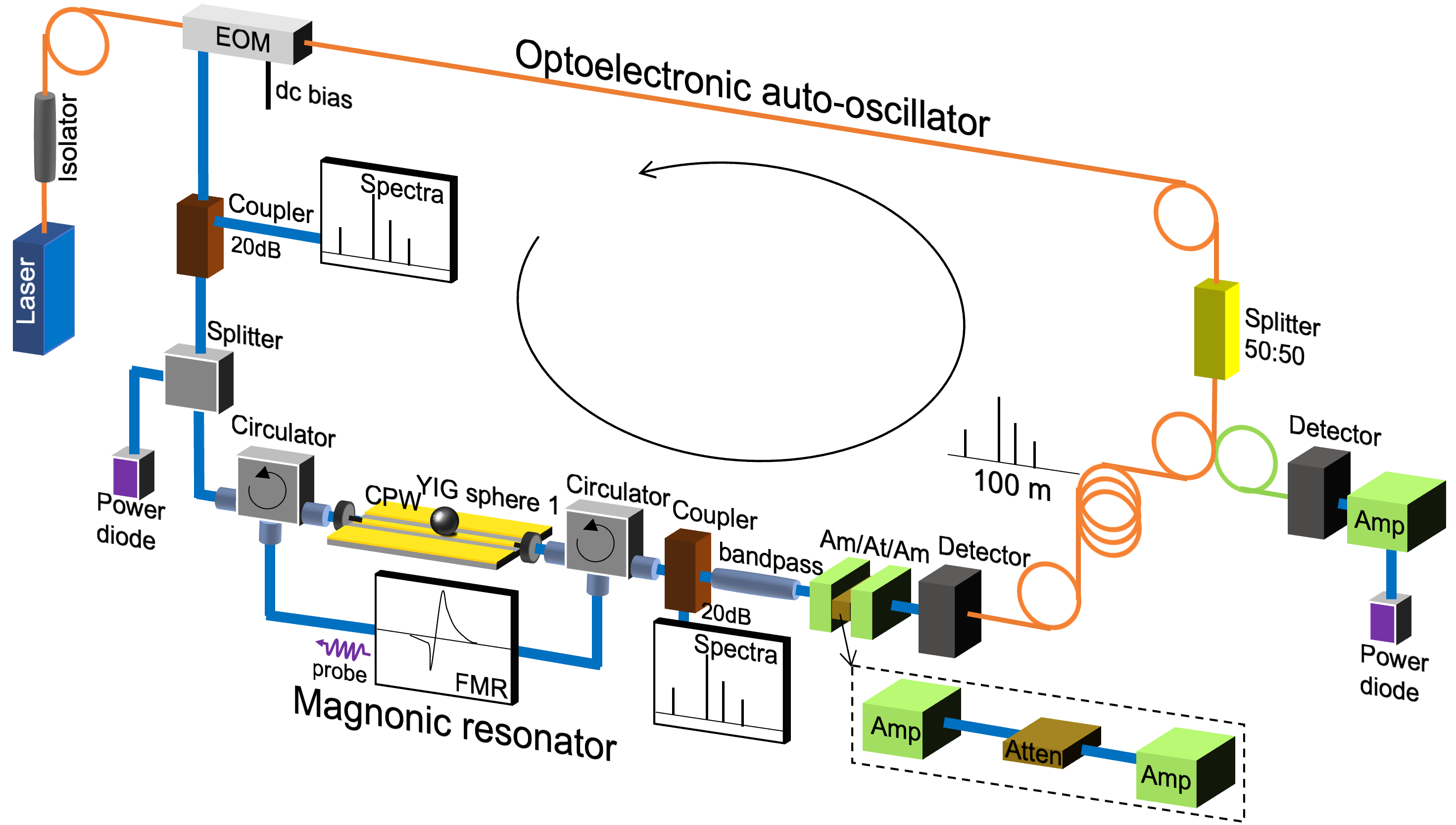
In this work, we integrated such an OEO with a magnonic oscillator consisting of a microwave waveguide and a YIG sphere, see Fig. 1. The coherent coupling, hybridization, and the back action between the oscillator’s photon mode (including its sideband harmonics) and the magnon mode were observed. Leveraging the mature fiber-optic technologies in optoelectronics, this work laid out a new, hybrid platform for investigating long-distance coupling and nonlinearity in coherent magnonic phoenomena.
II Setup Construction
As illustrated in Fig. 1, an intensity-stabilized fiber laser (1550 nm wavelength, power outpout 17 dBm from Optilab LLC) sources a continuous-wave (CW) light signal that first passes through an isolator, then an electro-optic modulator (EOM) that is biased at the appropriate dc level (0.8 - 1.5 V in our study). The signal is then divided into two branches using a 50:50 fiber light splitter. The right-hand branch can be used as a reference branch or a monitor branch, where the light signal converts to microwave by an ultrafast diode and then amplifies to a power diode for monitoring the optical power of the whole system.
The main branch (left) is one that entails the magnon resonator: after the light splitting, the signal passes through a fiber delayline, then converts to microwave via the ultrafast diode, and an optional bandpass filter, then amplifies by the “Am-At-Am” combo before meeting the magnon resonator. The Am-At-Am represents a tunable attenuator sandwiched between two fixed-gain amplifiers (+30 dBm) thus allowing the power level of the signal to be tuned before returning to the EOM (at the rf port).
The magnon resonator consists of a YIG sphere with a nominal radius mm placed on top of the signal line of a coplanar waveguide (CPW), and the whole structure is placed between a pair of circulators, to introduce an additional, reverse-circulating ”probe loop” that measures the ferromagnetic resonance (FMR) of the magnon resonator. An external magnetic field, , is applied to establish the magnon resonances and is set parallel to the CPW’s stripline. The probe loop microwave power is kept rather small (15 dBm) and causes no disturbance to the main loop which typically flows a microwave power 10 dBm. Once the signal leaves the magnon resonator, it is directed back to the EOM (rf port). Additional microwave splitters and/or couplers are inserted as needed for sampling and monitor the signal power and spectra at desirable positions along the loop.
III OEO Characteristics and YIG loading
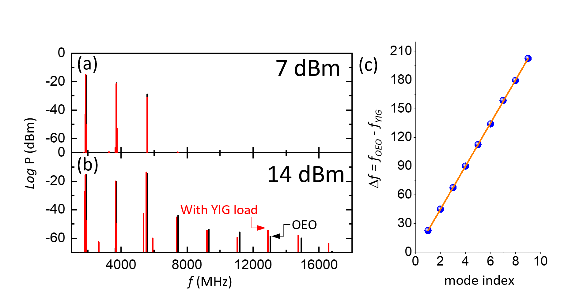
Upon a certain threshold power, self-sustained oscillation sharply establishes in the loop, which we define as the zero-gain (0 dB), to indicate the onset of the auto-oscillation. A series of eigen-modes in the form of sharp frequency peaks can be observed in the power spectra. As shown in Fig. 2(a), for the generic OEO without loading the magnon resonator, the loop power (as measured from the rf diode) to establish and maintain a robust self-oscillation is dBm, and 3 eigen-modes can be observed simultaneously. When the power increases, more eigen-modes start to emerge; for example, in Fig. 2(b), up to 9 pronounced eigen-modes were observed when the loop power is tuned to 14 dBm. The position of the modes shift sensitively by the length of the inserted fiber delayline (5, 100, 1000 m are used in this work) as well as the phase shifter, but depends weakly on the loop power (gain). For example, at 14 dBm power and a fiber length of 100 m, we observe a set of fundamental eigen-modes at 1864.4, 3729.6, 5594.8, 7459.4…MHz. These fundamental modes slightly shift to the lower frequency once the magnon resonator is inserted, as shown in Fig. 2(c).
III.1 Magnon-induced modulation of OEO power and spectra
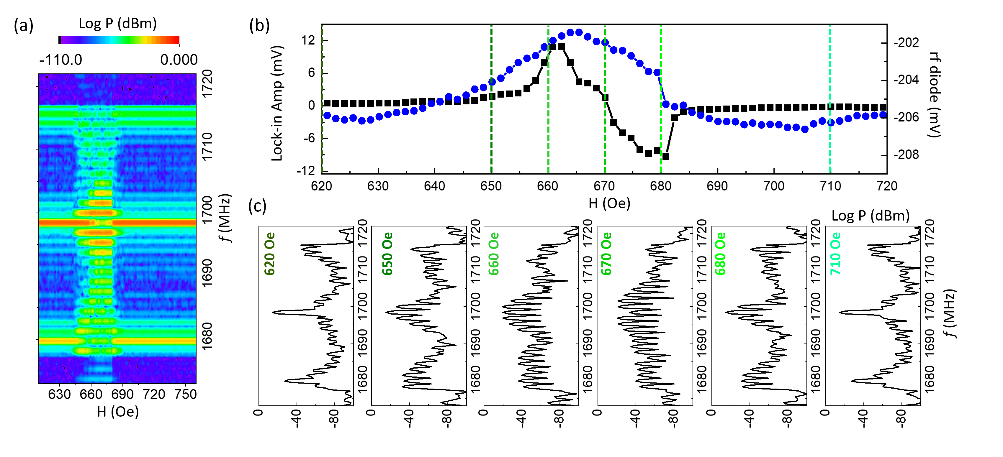
We first turn our attention to the 1st fundamental mode under the excitation of the magnon resonator. As an example, we use a fiber of 100 m in length and an additional phase shifter tuned to the optimized phase angle. The main mode resonates at 1698.4 MHz, with two pronounced sidebands at 1679.8 and 1715.7 MHz, shown in Fig.3. By sweeping the external magnetic field, this fundamental mode excites a YIG FMR at around 665 Oe, inducing a disturbance to the local power spectra near the FMR regime (from 650 to 680 Oe). At the same time, the probe-detected FMR signal and the microwave diode signal (monitoring the loop’s optical power) is measured concurrently. Due to the use of a negative video-out diode, an rf power increase corresponds to a diode readout decrease (more negative). As shown in Fig. 3(b), when the FMR is excited as evidenced by the FMR probe (black trace), the optical power of the loop is also correspondingly reduced as indicated by the change (increase) of the diode signal (blue trace).
Such a trait of the system to monitor the magnon resonator by the OEO loop power is likely related to their similar lifetime, where the OEO’s gain is not fast enough to respond to the energy dissipation from the magnon resonator. The YIG has a typical damping of and absorbs/dissipates energy to the OEO’s photon mode at a rate of tens to hundreds of ns; while the OEO relaxation is determined from its delay time, , can be estimated: , where and are the photonic and microwave (including magnonic part) delays, respectively. For long fibers, the time is driven primarily by the photonic delay, i.e., the fiber delay , where is the fiber length and the refractive index. The Corning SMF-28 fiber used in our system has a core index of refraction as 1.4682 at 1550 nm, so the speed of light can be estimated as 2.04 m/s. Therefore, the delay is on the order of ns. The spectrum evolution upon sweeping the magnetic field near the FMR regime is shown in Fig. 3(c) by series of snapshots of the spectrum. As the magnetic field is tuned from 660 Oe to 670 Oe, the amplitudes of the main resonance and its two sidebands gradually reduce, while a denser oscillation pattern shows up in the spectrum, which has a free spectral range (FSR) of 1.6 MHz likely governed by the phonon mode of YIG (via magnetostrictive coupling).
III.2 Magnon coupling with microwave photonic sidebands
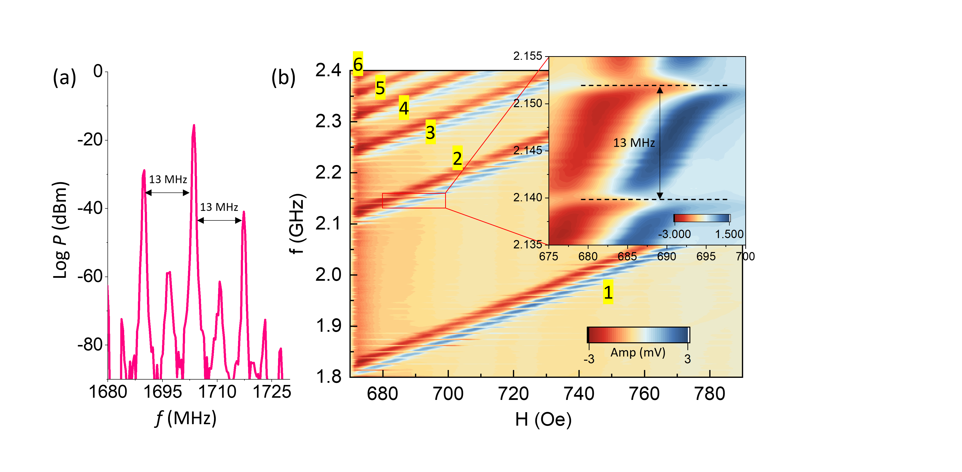
Next, we address how the OEO-excited YIG FMR interacts with a probe signal. Using the probe sub-loop, we scanned the dispersion of the magnon resonator near the 1st OEO main mode which resonates at around Oe according to Fig.3. A fiber delay of 5 m is used to mitigate the sensitivity of the spectra to the magnetic field while still observing the needed characteristics. The two sidebands are MHz apart from the central band, and all other harmonics are more than 40dB lower in power, see Fig. 4(a).
Under the strong OEO photon mode (akin to a distinct rf signal source), excitation of different magnetostatic modes at different magnetic fields are anticipated. As shown in Fig.4(b), a total of six magnetostatic modes (i.e., Walker modes / Whisper-gallery modes) were detected, which are launched near the 1st main OEO mode. We observe series of harmonic photon modes in the probed dispersion whose frequency spacing ( 13 MHz) matches the frequency difference between the main loop mode and the sidebands, Fig. 4(a). This array of photon modes is the result of intermixing between the main mode and the two sidebands. Hybridization between the magnetostatic modes and the series of the photon modes were observed in the dispersion, causing series of anticrossing gaps, which becomes more visually apparent by a fine-scanned window in the inset of Fig. 4(b). A coupling strength between the photon and magnon modes, as extracted from the anticrossing gap, is MHz.
IV Magnon-photon coupling with the OEO modes
Due to the relatively low frequency of the first OEO eigen-mode that lays beyond the magnon manifold, the higher order magnetostatic (Walker) modes of YIG cannot be effectively excited except for the main FMR in the probe sub-loop. Therefore, we shift our focus to the OEO eigen-mode at higher frequency, which resonates at MHz. By choosing the proper set of circulators and bandpass filters, we can pick out the OEO mode while suppressing all other eigen-modes and sidebands.
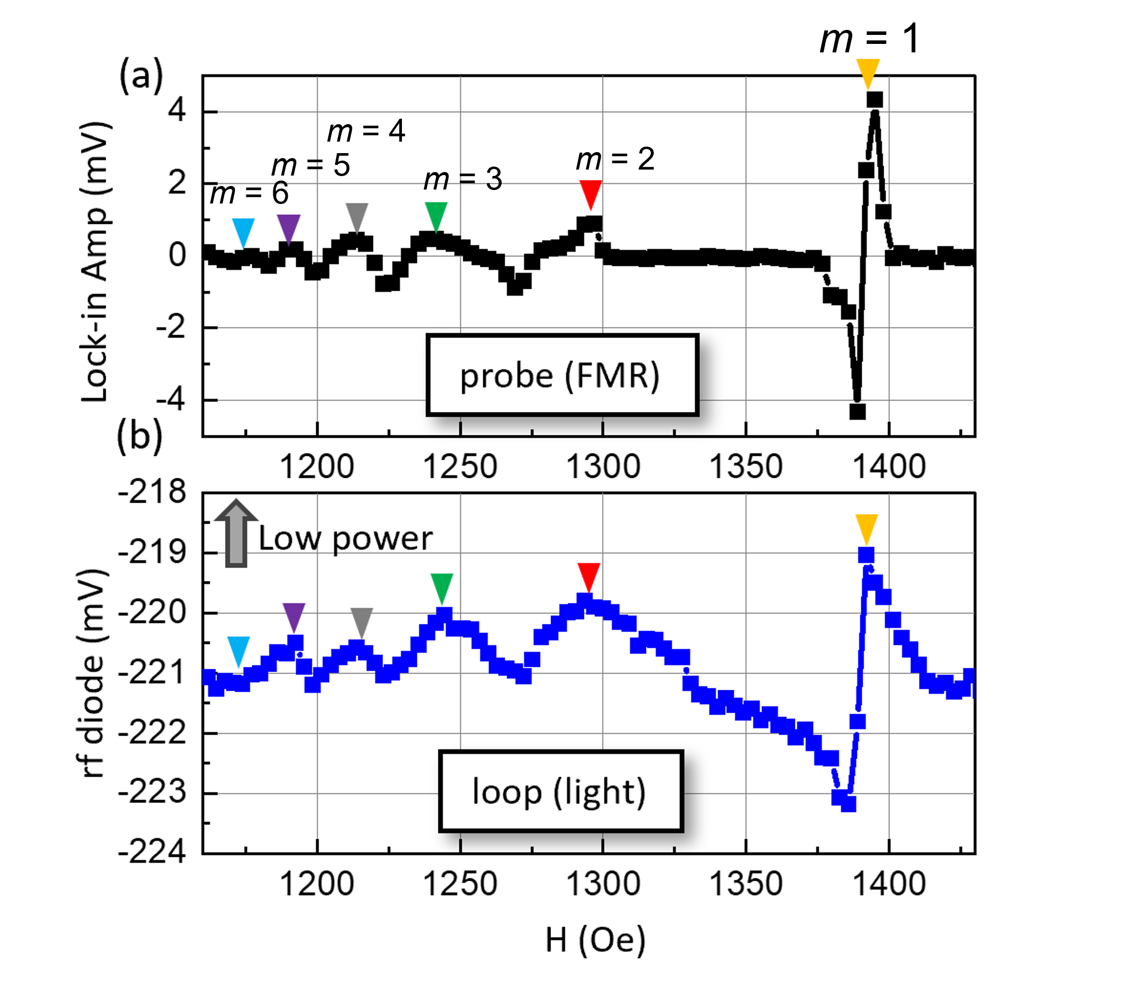
In the sub-loop, the magnon modes are probed by the transmission of a fixed-frequency rf tone (using the lock-in amplifier) while the bias magnetic field is scanned. Near this 2nd OEO eigen-mode, all the six magnetostatic modes of YIG can be concurrently observed, which is evidenced from both the magnon spectra using the probe sub-loop, in Fig. 5(a), as well as the power diode from the main loop, in Fig. 5(b). These modes are identified as the magnetostatic modes with mode order (), where is the angular mode number, and the fundamental mode () corresponds to the ferromagnetic resonance (FMR) mode.
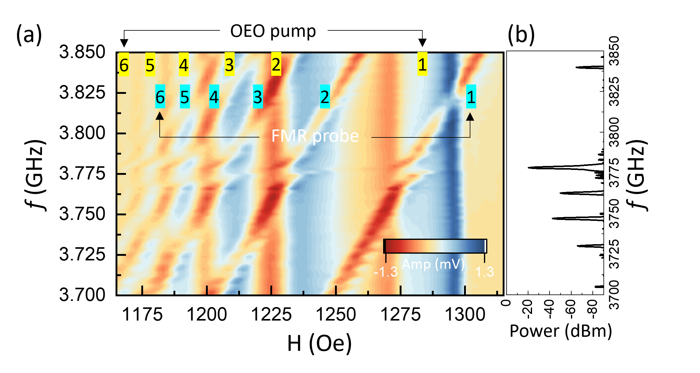
In addition, during the process, the strong OEO oscillation signal is also present inside the YIG resonator which acts as a strong pump to the magnon modes. Such a strong pump leads to a peculiar pump-induced mode pim , which then causes a pronounced back-action to the probed magnon resonance, depending on the relative detuning of the probe frequency with respect to the OEO oscillation frequency. Figure 6(a) plots the measured lock-in signal as a function of bias magnetic field and probe signal frequency, with the OEO oscillation frequency fixed at 3778.1 MHz.
We scan the probe signal (low power) near the OEO pump mode MHz, shown in Fig. 6(a). Notably, the pronounced back-action to the probe signal caused by the OEO pump mode leads to a reduction of the magnetostatic magnon amplitude, which, in turn suppresses the OEO pumping process. The net result is then the observation of an anti-crossing feature in the dispersion centered around the OEO pump mode, for all the magnetostatic modes.
V Theory of magnon-induced nonlinear sideband generation and magnon-photon coupling
In the absence of YIG, the frequency response of the OEO above the threshold displays equally spaced peaks analogous to that of a Fabry-Perot resonator. Therefore, we model the OEO modes as harmonic oscillators with ladder operators , , possessing resonance frequencies , where characterizes the frequency of the first fundamental OEO mode. The Hamiltonian of the OEO system is given by
| (1) |
The Hamiltonian of the YIG sphere, which accounts for spin-spin, dipole-dipole and Zeeman interactions, can be diagonalized as walker ; spinw
| (2) |
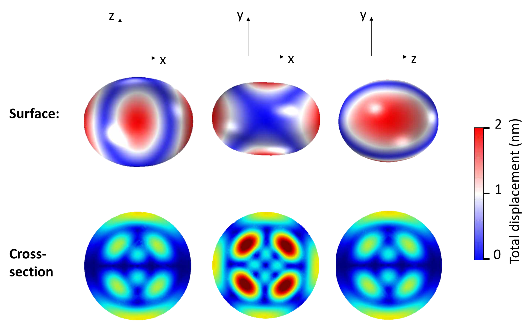
where () is the magnon annihilation (creation) operator and the magnon dispersion, which depends linearly on the applied bias magnetic field . The magnon and the OEO modes interact coherently through the evanescent fields emanating from the waveguide. In addition, the presence of strong OEO fields leads to non-negligible magnetostrictive interactions between magnons and phonons that owe their origin to the deformation of the YIG due to the varying magnetization inside the magnetic sphere you_prb2016 . Our COMSOL simulations confirm the phonon S3,2,2 mode at 13 MHz for the 1-mm-diameter YIG sphere, as shown in Fig. 7. Compared with the S1,2,2 mode used in Ref.zhang_sciadv2016 , this phonon mode has the same azimuthal symmetry and thus also couples efficiently with the magnon mode, while its large radial mode order (3) leads to reduced displacement at the sphere surface, which minimizes the contact loss to this phonon mode and accordingly lower self-oscillation threshold.
There are several magnon and OEO modes interacting coherently through the evanescent fields. For the sake of brevity, here we focus on the interaction between the second fundamental OEO mode and one of the Walker modes, where the operator () is superseded by () with corresponding frequency (). The approximate Hamiltonian of the interacting system, which can be straightforwardly generalized into other modes of the system, is given by
| (3) |
Here () denotes the annihilation (creation) operator of a phonon mode of frequency , and are respectively, the magnon-photon and magnon-phonon interaction strengths, whereas parameterizes the strength of the field pumping the OEO mode. The dynamics of the system in the frame rotating at frequency is provided by the following mean-field equations:
| (4) |
where () while and are, respectively the damping rates of the associated modes. In the long-time limit, the general solution to the modes in Eq. (V) takes the form
| (5) |
Equation (V) shows that the nonlinear interactions lead to the generation of sidebands oscillating at frequencies displaced by an integer multiple of around . The coefficients () can be obtained by substituting Eq. (V) into Eq. (V). For instance,
| (6) |
where . The sidebands get self-sustained through the OEO and the corresponding modes appear in the power spectra as shown in Fig. 2. The approximate Hamiltonian of the second fundamental OEO mode and associated sidebands interacting with the magnon mode can be modelled as
| (7) |
where () denotes the annihilation (creation) operator of the sideband while is the pump-induced mode. The strength of coupling between the magnon and the pump-induced mode is a function of the intensity of the incident electromagnetic field. Information regarding the eigenstructure of the system can be extracted from the transmission to a weak probe field of frequency applied on the system. The input-output relation relevant to the probe transmission is given by
| (8) |
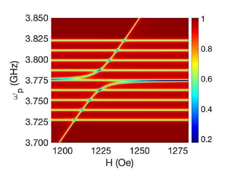
where and characterize the input and transmitted fields respectively, while is the strength of coupling between the probe field and the modes of the system. In Fig. 8, we plot the numerically calculated transmission coefficient by keeping eight sidebands of the fundamental OEO modes 111The frequency where represents the gyromagnetic ratio and is a shift chosen to match one of the Walker modes in Fig. 6.. Clearly, the level-splitting at the fundamental OEO frequency (due to photon-magnon coupling with the pump-induced mode) is significantly larger than the one displayed by the sidebands (due to phonon-magnon coupling), in agreement with the experimental observations of level-repulsion showcased in Fig. 6.
In summary, we report a new platform of studying magnon-photon coupling by integrating an opto-electronic resonator with a magnonic resonator. The OEO mode is a self-sustained photon mode that is stabilized by the time-delay of the system. Both the OEO loop’s power and spectrum can be greatly altered by the existence of the additional magnon resonator: due to the similar response time of the photon and magnon counterparts, the loop power changes following the magnon resonance; the mode energy smears out to additional phonon modes of YIG due to the magnetostrictive coupling. Reciprocally, the magnon modes induce nontrivial back-action to the OEO mode (in the form of a pump), and an anticrossing gap is observed between the magnetostatic magnons and the OEO modes which is phenomenologically analogous to the common strong coupling between magnon and photon.
Acknowledgment
The experimental work at UNC-CH was supported by the U.S. National Science Foundation under Grant No. ECCS-2246254. B. Flebus acknowledges support from National Science Foundation under Grant No. NSF DMR-2144086.
Author Contributions
B.F. and W.Z. conceived the idea. Y.X., A.C.,J.C., and W.Z. performed the experiment and data analysis. J.N. and B.F. developed the theoretical model. A.P. and X. Z. performed the COMSOL simulation. All authors contributed to the writing of the manuscript.
Competing interests
All authors declare no financial or non-financial competing interests.
Data availability
The datasets used and/or analysed during the current study available from the corresponding author on reasonable request.
References
- (1) D. Lachance-Quirion, Y. Tabuchi, A. Gloppe, K. Usami, and Y. Nakamura, “Hybrid quantum systems based on magnonics”, Applied Physics Express 12, 070101 (2019).
- (2) M. Harder and C. -M. Hu, “Cavity Spintronics: An Early Review of Recent Progress in the Study of Magnon-Photon Level Repulsion”, Solid State Physics, 70, 47 - 121 (2018). R. Stamps and R. Camley (Ed.), Academic Press.
- (3) B. Bhoi and S. -K. Kim, “Photon-magnon coupling: Historical perspective, status, and future directions”, Solid State Physics, 69, 1 - 77 (2019). R. Stamps and H. Schultheiss (Ed.), Academic Press.
- (4) D. D. Awschalom, C.H.R. Du, R. He, J. Heremans, A. Hoffmann, J. Hou, H. Kurebayashi, Y. Li, L. Liu, V. Novosad, J. Sklenar, S. Sullivan, D. Sun, H. Tang, V. Tyberkevych, C. Trevillian, A. W. Tsen, L. Weiss, W. Zhang, X. Zhang, L. Zhao, and Ch. W. Zollitsch, “Quantum Engineering With Hybrid Magnonics Systems and Materials”, IEEE Trans. Quantum Engineering 2, 5500836 (2021).
- (5) Y. Li, W. Zhang, V. Tyberkevych, W.-K. Kwok, A. Hoffmann, V. Novosad, “Hybrid magnonics: Physics, circuits, and applications for coherent information processing”, J. Appl. Phys. 128, 130902 (2020).
- (6) Y. Tabuchi, S. Ishino, A. Noguchi, T. Ishikawa, R. Yamazaki, K. Usami, and Y. Nakamura, “Coherent coupling between a ferromagnetic magnon and a superconducting qubit”, Science 349, 405 (2015).
- (7) L. McKenzie-Sell, J. Xie, C.-M. Lee, J. W. A. Robinson, C. Ciccarelli, and J. A. Haigh, “Low-impedance superconducting microwave resonators for strong coupling to small magnetic mode volumes”, Phys. Rev. B 99, 140414 (2019).
- (8) Y. Li, T. Polakovic, Y.-L. Wang, J. Xu, S. Lendinez, Z. Zhang, J. Ding, T. Khaire, H. Saglam, R. Divan, J. Pearson, W. K. Kwok, Z. Xiao, V. Novosad, A. Hoffmann, and W. Zhang, “Strong Coupling between Magnons and Microwave Photons in On-Chip Ferromagnet-Superconductor Thin-Film Devices”, Phys. Rev. Lett. 123, 107701 (2019).
- (9) J. T. Hou and L. Liu, “Strong coupling between microwave photons and nanomagnet magnons”, Phys. Rev. Lett. 123, 107702 (2019).
- (10) H. Huebl, C. W. Zollitsch, J. Lotze, F. Hocke, M. Greifenstein, A. Marx, R. Gross, and S. T. B. Goennenwein, “High Cooperativity in Coupled Microwave Resonator Ferrimagnetic Insulator Hybrids”, Phys. Rev. Lett. 111, 127003 (2013).
- (11) L. Bai, M. Harder, Y. P. Chen, X. Fan, J. Q. Xiao, and C. M. Hu, “Spin Pumping in Electrodynamically Coupled Magnon-Photon Systems”, Phys. Rev. Lett. 114, 227201 (2015).
- (12) X. Zhang, C.-L. Zou, L. Jiang, and H. X. Tang, “Strongly Coupled Magnons and Cavity Microwave Photons”, Phys. Rev. Lett. 113, 156401 (2014).
- (13) Shasha Zheng, Zhenyu Wang, Yipu Wang, Fengxiao Sun, Qiongyi He, Peng Yan, H. Y. Yuan, “Tutorial: Nonlinear magnonics”, arXiv:2303.16313 (2023).
- (14) Mehrdad Elyasi, Yaroslav M. Blanter, and Gerrit E. W. Bauer, “Resources of nonlinear cavity magnonics for quantum information”, Phys. Rev. B 101, 054402 (2020).
- (15) Jinwei Rao, C. Y. Wang, Bimu Yao, Z. J. Chen, K. X. Zhao, Wei Lu, “Meter-scale strong coupling between magnons and photons”, Phys. Rev. Lett. in press (2013).
- (16) Bimu Yao, Y.S. Gui, J.W. Rao, Y.H. Zhang, Wei Lu, and C.-M. Hu, “Coherent Microwave Emission of Gain-Driven Polaritons”, Phys. Rev. Lett. 130, 146702 (2023).
- (17) J.W. Rao, Bimu Yao, C.Y. Wang, C. Zhang, Tao Yu, and Wei Lu, “Unveiling a Pump-Induced Magnon Mode via Its Strong Interaction with Walker Modes”, Phys. Rev. Lett. 130, 046705 (2023).
- (18) Daniel D. Stancil, Spin Waves: Theory and Applications, Springer, 2009 Edition.
- (19) S. O. Demokritov, V. E. Demidov, O. Dzyapko, G. A. Melkov, A. A. Serga, B. Hillebrands, and A. N. Slavin, “Bose–Einstein condensation of quasi-equilibrium magnons at room temperature under pumping”, Nature 443, 430 (2006).
- (20) A. J. E. Kreil, D. A. Bozhko, H. Yu. Musiienko-Shmarova, V. I. Vasyuchka, V. S. L’vov, A. Pomyalov, B. Hillebrands, and A. A. Serga, “From Kinetic Instability to Bose-Einstein Condensation and Magnon Supercurrents”, Phys. Rev. Lett. 121, 077203 (2018).
- (21) M. Schneider, D. Breitbach, R. O. Serha, Q. Wang, A. A. Serga, A. N. Slavin, V. S. Tiberkevich, B. Heinz, B. Lägel, T. Brächer, C. Dubs, S. Knauer, O. V. Dobrovolskiy, P. Pirro, B. Hillebrands, and A. V. Chumak, “Control of the Bose-Einstein Condensation of Magnons by the Spin Hall Effect”, Phys. Rev. Lett. 127, 237203 (2021).
- (22) M. Mohseni, A. Qaiumzadeh, A. A. Serga, A. Brataas, B. Hillebrands, and P. Pirro, “Bose–Einstein condensation of nonequilibrium magnons in confined systems”, New J. Phys. 22 083080 (2020).
- (23) T. Hache, L. Körber, T. Hula, K. Lenz, A. Kákay, O. Hellwig, J. Lindner, J. Fassbender, and H. Schultheiss, “Control of Four-Magnon Scattering by Pure Spin Current in a Magnonic Waveguide”, Phys. Rev. Applied 20, 014062 (2023).
- (24) R.-C. Shen, J. Li, Z.-Y. Fan, Y.-P. Wang, and J. Q. You, “Mechanical Bistability in Kerr-Modified Cavity Magnomechanics”, Phys. Rev. Lett. 129, 123601 (2022).
- (25) Z. Wang, H.-Y. Yuan, Y. Cao, Z.-X. Li, R. A. Duine, and P. Yan, “Magnonic Frequency Comb Through Nonlinear Magnon-Skyrmion Scattering”, Phys. Rev. Lett. 127, 037202 (2021).
- (26) T. Hula, K. Schultheiss, F. J. T. Gonçalves, L. Körber, M. Bejarano, M. Copus, L. Flacke, L. Liensberger, A. Buzdakov, A. Kákay, M. Weiler, R. Camley, J. Fassbender, and H. Schultheiss, “Spin-wave frequency combs”, Appl. Phys. Lett. 121, 112404 (2022).
- (27) S. Muralidhar, A. A. Awad, A. Alemán, R. Khymyn, M. Dvornik, D. Hanstorp, and J. Åkerman, “Sustained coherent spin wave emission using frequency combs”, Phys. Rev. B 101, 224423 (2020).
- (28) H. Xiong, “Magnonic frequency combs based on the resonantly enhanced magnetostrictive effect”, Fundamental Res. 3, 8 (2023).
- (29) Yanne K. Chembo, Daniel Brunner, Maxime Jacquot, and Laurent Larger, “Optoelectronic oscillators with time-delayed feedback”, Rev. Mod. Phys. 91, 035006 (2019).
- (30) Yuzan Xiong, Zhizhi Zhang, Yi Li, Mouhamad Hammami, Joseph Sklenar, Laith Alahmed, Peng Li, Thomas Sebastian, Hongwei Qu, Axel Hoffmann, Valentine Novosad, and Wei Zhang, “Experimental parameters, combined dynamics, and nonlinearity of a magnonic-opto-electronic oscillator (MOEO)”, Rev Sci Instrum 91, 125105 (2020).
- (31) A. B. Ustinov, A. A. Nikitin, and Boris A. Kalinikos, ”Magnetically Tunable Microwave Spin-Wave Photonic Oscillator”, IEEE Magn. Lett. 6, 3500704 (2015).
- (32) V. V. Vitko, A. A. Nikitin, A. B. Ustinov, and Boris A. Kalinikos, ”Microwave Bistability in Active Ring Resonators With Dual Spin-Wave and Optical Nonlinearities”, IEEE Magn. Lett. 9, 3506304 (2018).
- (33) Stuart Watt, Mikhail Kostylev, Alexey B. Ustinov, and Boris A. Kalinikos, “Implementing a Magnonic Reservoir Computer Model Based on Time-Delay Multiplexing”, Phys. Rev. Applied 15, 064060 (2021).
- (34) Stuart Watt and Mikhail Kostylev, “Learning Trajectories from Spin-Wave Dynamics”, Phys. Rev. Applied 19, 064029 (2023).
- (35) Stuart Watt and Mikhail Kostylev, “Reservoir Computing Using a Spin-Wave Delay-Line Active-Ring Resonator Based on Yttrium-Iron-Garnet Film”, Phys. Rev. Applied 13, 034057 (2020).
- (36) T. Holstein and H. Primakoff, “Field Dependence of the Intrinsic Domain Magnetization of a Ferromagnet”, Phys. Rev. 58, 1098 (1940).
- (37) L. R. Walker, “Resonant Modes of Ferromagnetic Spheroids”, J. Appl. Phys. 29, 318–323 (1958).
- (38) D. D. Stancil and Anil Prabhakar, “Spin waves” Vol. 5. New York: Springer, (2009).
- (39) Yi-Pu Wang, Guo-Qiang Zhang, Dengke Zhang, Xiao-Qing Luo, Wei Xiong, Shuai-Peng Wang, Tie-Fu Li, C.-M. Hu, and J. Q. You, “Magnon Kerr effect in a strongly coupled cavity-magnon system”, Phys. Rev. B 94, 224410 (2016).
- (40) Xufeng Zhang, Chang-Ling Zou, Liang Jiang, and Hong Tang, “Cavity magnomechanics”, Sci. Adv. 2, e1501286 (2016).