Additive manufacturing of a 3D-segmented plastic scintillator detector for tracking and calorimetry of elementary particles
Abstract
Plastic-scintillator detectors are among the most common devices used for the detection of elementary particles. They provide good particle identification combined with excellent time resolution, whilst being inexpensive due to the affordability of plastic materials. Particle tracking is achieved by segmenting the scintillator into smaller, independent, optically-isolated voxels. Enhancing the performance of future particle detectors necessitates larger total volumes, possibly combined with even finer segmentation. However, manufacturing such designs with current production strategies is challenging. These strategies involve a variety of time-consuming and costly fabrication processes, followed by the assembly of millions of individual parts. The difficulty in scaling up such a complex workflow underscores the need for technological advancements, which can be met by additive manufacturing. This method enables the construction of complex, monolithic geometries in a single operation. These geometries consist of fine three-dimensional granular sub-structures and require the integration of multiple types of plastic materials, as well as space to accommodate optical fibers, all within a compact volume of several cubic meters.
This article presents the fabrication and performance evaluation of the first additive manufactured single-block plastic scintillator detector. To achieve this, a new method called Fused Injection Modeling has been specially developed. The detector is capable of three-dimensional tracking of elementary particles and accurately measuring their stopping power. Its performance is comparable to the current state of the art of plastic scintillator detectors. This work paves the way towards a new feasible, time and cost-effective process for the production of future scintillator detectors, regardless their size and difficulty in geometry.
I Introduction
Plastic scintillator (PS) detectors, invented in the early 1950s [1], are widely used in the detection of elementary particles in high-energy physics, nuclear physics, astroparticle physics, as well as in many applications like muon tomography, proton computed tomography for hadron therapy, fast-neutron detection and non-destructive imaging.
By measuring the energy loss of a particle and tracking its path in the detector, it is possible to identify the type of interacting particle, reconstruct its momentum based on range, measure its original energy using calorimetry, and determine its electric charge if the setup is immersed in a magnetic field.
Another important feature of PS detectors is their unique ability to provide an extremely fast response, with time resolution in the sub-nanosecond range.
PS detectors are typically made of
long scintillating bars with O(cm) granularity for time-of-flight detectors
[2, 3], neutrino active targets with tonne-to-kilotonne scale mass [4, 5, 6],
sampling calorimeters made by layers of segmented PS alternated with heavier materials like iron and lead [7],
or scintillating optical fibers [8] with a diameter down to .
A PS is an organic material composed of a mixture of carbon and hydrogen-based molecules, typically polystyrene (PST) or polyvinyltoluene (PVT). Molecules of an activator like p-terphenyl (pTP), 2,2-p-phenilene-bis(5-pheniloxazole) (POPOP), 2,5- diphenyloxazole (PPO) are introduced into the polymer at a level between a few per mille or percent by weight. Such formula has not undergone any major change in the last fifty years.
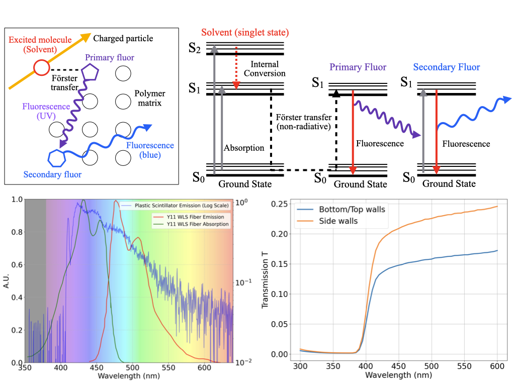
The scintillation mechanism consists of a few steps, highlighted in Fig. 1.
When a charged particle propagates through a PS, the molecules of the polymer matrix get excited. A fast short-range resonant non-radiative dipole-dipole interaction, called Förster mechanism [9], efficiently transfers the excitation energy to the activator, which de-excites and emits near-ultraviolet (UV) photons with a minimal emission delay. A second dopant, called a shifter, is usually added to change the wavelength of the light to avoid absorption in the material. More details about the scintillation mechanism in organic materials can be found in [10, 11].
Often, the light produced in PS is collected by wavelength-shifting (WLS) fibers. These fibers shift the light from the violet/blue spectrum, which is the typical emission range of PSs, to green, where the attenuation length is maximum.
They then guide it towards photodetectors, benefiting from the over several meters low attenuation length of the fiber [4].
Traditionally, PSs are manufactured with: (1) cast polymerization [12], where a heated liquid monomer with dissolved dopants is poured into a mold, that results in a solid plastic structure after cooling; (2) injection molding [13, 14], where polymer granules compounded with dopants are melted and mechanically forced into a mold to solidify; (3) extrusion [15, 16], which pushes melted plastic through a die of the desired cross section. While cast polymerization provides the best optical properties, the more commonly used injection molding and extrusion offer a simpler, faster and cheaper production, hence optimal for large-volume detectors [16].
PS detectors with tracking capabilities are made of scintillating voxels, which are optically isolated from each other. The typical light reflector is composed of a white diffuser, such as paint containing titanium dioxide (), white polytetrafluoroethylene (PTFE), or is created using a process of chemical etching [17]. Co-extrusion of PS and optical reflector has also been conducted [6, 4]. Another option with good performance consists of wrapping each scintillating element with Tyvek [18]. However, such a solution is unfeasible for detectors with a large number of PS elements [19, 20, 21].
In recent years, there have been advancements in the development of novel three-dimensional (3D) granular scintillating detectors for imaging electromagnetic and hadronic showers [22], as well as neutrino interactions [23, 19, 20, 21]. Combining these geometries with the PS sub-ns response is ideal for efficient neutron detection with kinetic energy reconstruction by time-of-flight [24, 25, 26, 27]. For instance, a neutrino detector made of two-million PS cubes, each of size 1 cm3, with a total active mass of two tonnes, has been proposed [19], prototyped [20, 21], and has been built and under commission as of 2023 at the T2K neutrino experiment in Japan [28]. The complexity in geometry of such a detector requires multiple vastly different manufacturing steps including the fabrication of every single PS cube, optical isolation via chemical etching and drilling of the holes for WLS fiber placement. Additionally, the assembly of two-million cubes demands a significant amount of effort [29] and needs to be combined with a robust box that mechanically maintains the structural integrity of the entire construction [28].
Attempts to simplify detector fabrication were reported in Ref. [30], where a prototype of PS cubes glued together was obtained with a tolerance of about 200 m. However, such a method is not feasible for the production of a single 3D volume of PS cubes, but only of 2D layers, whose production would also be time consuming for large-scale applications. The above considerations call for the development of a novel manufacturing process that allows for the easy production of several thousand optically-isolated PS cubes in a single block of plastic. Our solution takes advantage of additive manufacturing (AM), which opens the door to new automated processes that could drastically simplify the construction of future particle detectors. More commonly known as rapid prototyping or 3D printing, AM processes build the designed parts through a layer-by-layer addition of new material. AM technologies are capable of fabricating customizable, monolithic parts with multiple materials and complex internal geometries, and can greatly reduce production time and cost. Two common AM technologies for polymers are: stereolithography (SLA) [31], where liquid resin is solidified after curing with, for example, ultraviolet (UV) light; and Fused Deposition Modeling (FDM) [32], where, analogous to extrusion, a thermoplastic material in the form of a thin wire is passed through a feeding into a melting system and deposited on a print bed line-by-line with the help of a nozzle tip [33, 34]. 3D printing of PS with SLA has been reported in literature. However, studies have shown the necessity of either developing a new chemical composition or binding PS granules into a polymer matrix. This poses a challenge in achieving competitive performance levels in terms of acceptable light yield and attenuation length compared to standard PS [35]. Furthermore, it is not an easy task to achieve 3D printing of multiple materials, along with the production of hollow objects that possess smooth and consistent inner surfaces, which is needed for the insertion of WLS fibers.
As we have shown in Ref. [36], the most promising additive manufacturing option is FDM. It allows the use of the same chemical composition as standard scintillators in the form of a filament, ensures high transparency and multi-material printing. For more details on the FDM process and the naming convention of its components, we refer to Sec. IV.2. Furthermore, we have demonstrated that FDM can successfully 3D print PST-based scintillators. These scintillators are extensively utilized in particle detectors and exhibit a light yield performance comparable to the current state of the art. Another independent work reached a similar conclusion [37]. Later, we showed a technical attenuation length of about 19 cm measured in a bar of 5 cm in length, sufficient for fine-granularity scintillator detectors [38].
The absorption and emission spectra of the 3D printed PS are shown in Fig. 1. For such a scintillator composition, the emission spectrum of the 3D printed PS peaks around 420 nm upon the excitation with 386 nm light. This result is consistent with the UPS-923A standard scintillator reported in [39]. It also shows that the measured scintillation spectrum closely matches the absorption spectrum of green WLS fibers such as the Kuraray Y11 [40], allowing for an efficient readout of the scintillation light. In Ref. [38], the first 3D printed matrix of PS cubes optically isolated with a custom-fabricated white reflective filament (PST, or polymethyl methacrylate (PMMA)) mixed with was produced and showed a low cube-to-cube light crosstalk, less than 2%. However, after 3D printing, no work reported in literature could avoid the use of subtractive processes, like polishing the outer surface to achieve a good geometrical tolerance. Moreover, none of the studies ever attempted to 3D print hollow PS objects to host WLS fibers.
In this work, we present the first-ever demonstration of additive manufacturing of a 3D-segmented, fine-granularity PS detector without requiring any post-processing. A SuperCube, consisting of a matrix of 1 optically-isolated cubes, was additively manufactured and tested. Each cube includes cylindrical holes to house WLS fibers throughout the entire detector.
II Results
Previous R&D on this topic carried out by the authors in [36, 38] did not yield a particle detector of sufficient quality, as described in Sec. I. However, it was useful in defining the extrusion temperature of the PS at which there is no loss of the original scintillation light yield and it showed the producibility of an excellent performing optically reflective filament.
In this work, a novel manufacturing method named Fused Injection Modeling (FIM) was developed to obtain good geometrical tolerances, high transparency PS volumes, as well as precise hole fabrication for the placement of WLS fibers at a rapid production speed, thereby overcoming the aforementioned shortcomings of the AM fabricated PS particle detector. FIM merges the geometrical freedom of manufacturing of FDM with the production speed and high part density of injection molding by 3D printing an optically reflective frame containing the desired voxel shape and quantity, which is filled by rapidly pouring melted PS into the empty cavities to accurately shape the geometry of the PS (detailed depiction in Fig. 7).
To achieve a fast, high-quality, consistent forming of the PS structure, a customized liquefaction system integrated into an FDM machine was developed. Standard FDM melting components were analyzed and modified to cope with the increased thermal demands of a rapid heat transfer towards the low thermally conductive PS, while guaranteeing a working temperature in the filament feeding parts of the extrusion system. To distribute scintillation material evenly throughout the entire volume, an elongated nozzle was manufactured that provided freedom of movement within the already fabricated cavity. It was coupled with a spring-pressurized plate that constrained the melt pool within its mold while allowing air to escape the volume during the forming process. A more in depth explanation of the custom-made extrusion system can be found in Sec. IV.
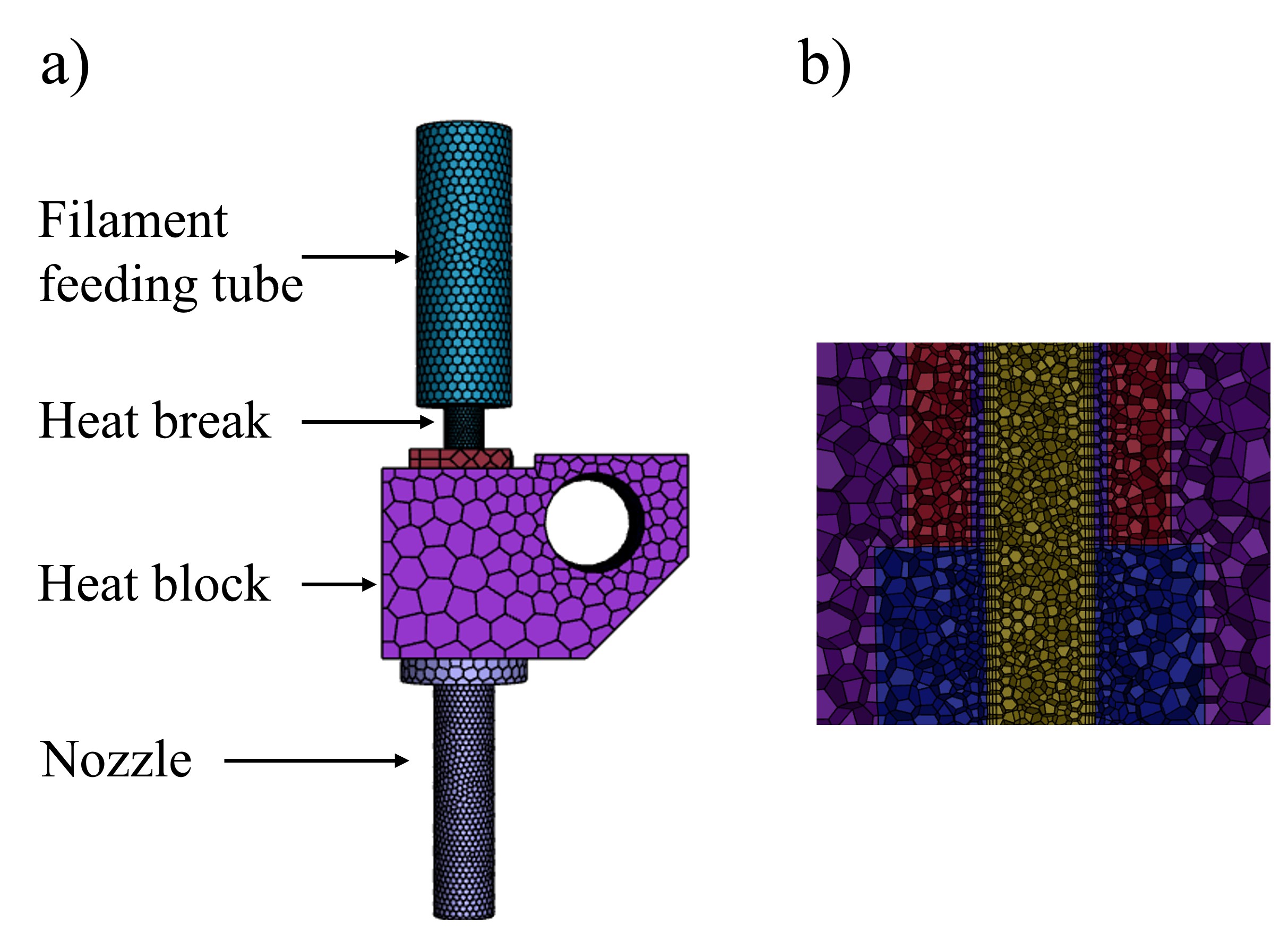
A Computational Fluid Dynamics (CFD) analysis was performed to determine the material requirements of the melting components, heat block and nozzle; the heat shielding parts, feeding tube and heat break; combined with the process parameters, heat block temperature, extrusion speed, and polymer temperature at the nozzle orifice. A detailed explanation of the nomenclature of the machine components, design and mode of operation of the manufacturing process is found in Sec. IV.2.
The results of the CFD analysis concluded that both the heat block and the nozzle needed to be manufactured with copper. Its high thermal conductive property enables a rapid heat transfer to the low thermally conductive PST-based PS filament, such that the desired melt temperature could be reached at high extrusion speeds. The feeding tube had to be fabricated with polyether ether ketone (PEEK), the heat break with stainless steel and a wall-thickness of 250 m. The low thermal conductivity of these materials combined with the small cross-section of the heat break results in a highly thermal resistant structure that prohibits heat flow towards the temperature sensitive parts and maintains a working temperature of the whole extrusion system. This composition of components resulted in the optimal process parameters of: a maximum throughput-speed of 15 mm/s to generate a high mass flow that quickly spreads within the cavity before solidifying; at a peak heat block temperature of 300°C, with which premature melting followed by system clogging can be avoided. This combination results in a temperature of around 230°C throughout the entire cross-section of the PS at the nozzle orifice, which preserves the scintillation properties established in [36, 38] (Fig. 2, left).
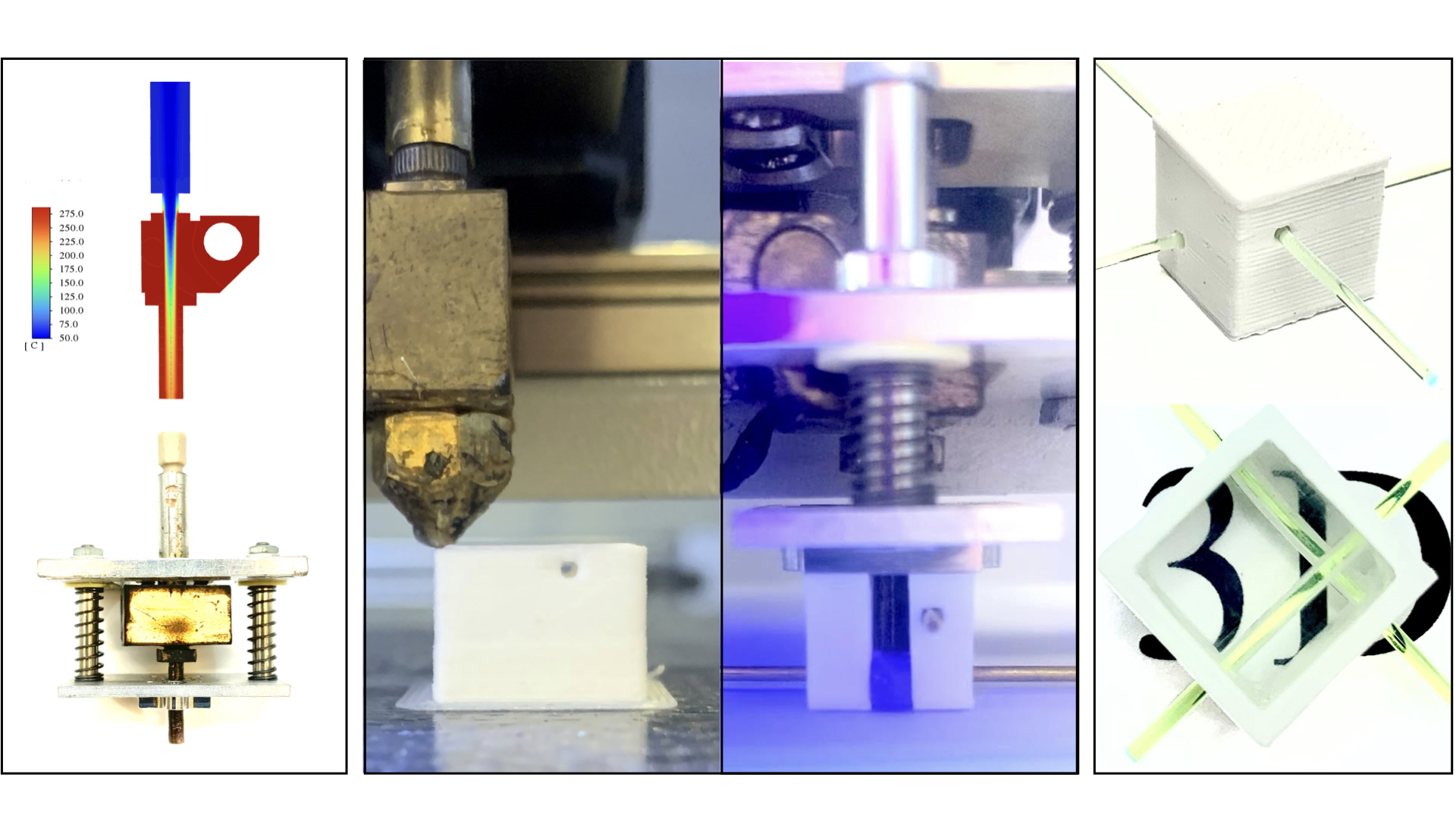
The performance of the custom heat break was tested by measuring its temperature with a thermocouple at a heat block temperature of 300°C and no filament extrusion. The results showed a 43.2% temperature reduction from 155°C to 88°C compared to a standard model heat break. This value lies below the glass transition temperature of the PS (100°C), thus ensures a failure free extrusion process.
The fabrication procedure, using the custom manufactured modified extrusion system (Fig. 2, left, bottom), contained three main steps and is described in more detail in Sec. IV: the fabrication of one matrix-layer of the reflective frame via FDM; the insertion of metal rods into the voxel cavity through already 3D-printed holes in the frame; followed by the forming of the cube-shaped volume with melted scintillation material (Fig. 2, middle). These processes can be repeated until a SuperCube of the desired size has been obtained. Finally, the WLS fibers were placed through the PS voxel via the cylindrical holes produced by the metal rods (Fig. 2, top right).
The optically reflective frame constituted the mold with which the PS was formed and thus needed to withstand the pressure and heat from the extruded melt pool. As reported in our previous work [38], in order to manufacture a 3D printed layer of optically-isolated cubes, a custom optical reflector filament was fabricated with either PMMA or PST. A transmittance of less than 10% and an optical cube-to-cube light crosstalk of less than 2% were achieved, the material could not maintain its structural integrity during the injection of the PS. This was due to the similar heat resistance of the optical reflector compared to the PS, with the consequence of swelling and wall bending during filling. Hence, for the FIM method, a white, more heat-resistant polycarbonate-PTFE filament was used, which combines good optical properties of PTFE and a heat-resistance significantly higher than the previously used materials.
In FDM, vertical walls are created by stacking lines on top of each other, while horizontal walls are formed by placing adjacent lines on the same print plane. This results in different fill factors, thus different light transmissive properties. The corresponding transmittance for a wavelength of 420 nm, measured with a monochromatic light source, resulted in 13% for horizontally and 18% for vertically built walls, as shown in Fig. 1. Consequently, to obtain a uniform cube-to-cube light crosstalk, horizontal walls were fabricated with a thickness of 1.2 mm and the more transmissive vertical walls with 1.5 mm. The more heat-resistant reflective material retained its as-built cube shape throughout the filling fabrication of the PS, as can be seen in Fig. 2, bottom right. Caliper measurements of vertical walls showed an average thickness of = 1.51 mm, deviating by only 0.01 mm from the nominal = 1.5 mm with a standard deviation of = 0.01 mm. Both the retention of the reflective frame geometry after filling and the accurate fabrication of the wall thickness ensured a consistent active volume of scintillation material in every voxel. More details about the fabrication of the white reflector walls can be found in Sec. IV.2.1.
The established process parameters combined with the custom manufactured elongated nozzle and melt-pool-containing pressurized plate resulted in a transparent PS volume with a high fill factor around the metal rods, which left precisely positioned and close-fitting holes for the insertion of WLS fibers. In Ref. [36] a technical attenuation length of about 19 cm was measured and found to be sufficient for highly-segmented detectors. The FIM-fabricated PS showed an even improved transparency and no air bubbles compared to the samples produced with FDM (Fig. 2, bottom right).
The manufacturing time per an entire unit, depicted top right in Fig. 2, was approximately 6 minutes. This involved the fabrication of the reflective frame and the forming of the PS. Fixed time cost, including the not-yet fully automated change between the FDM and injection set-up, was around 20 minutes, plus an additional 15 minutes for an initial warm-up of the machine.
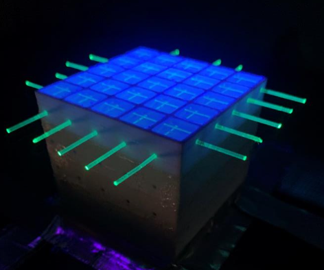
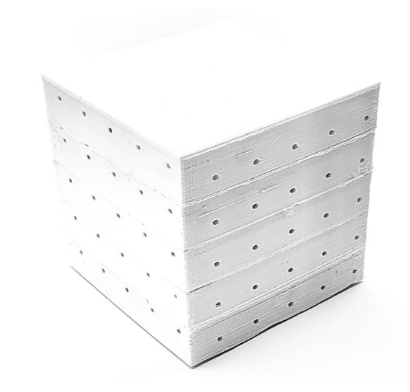
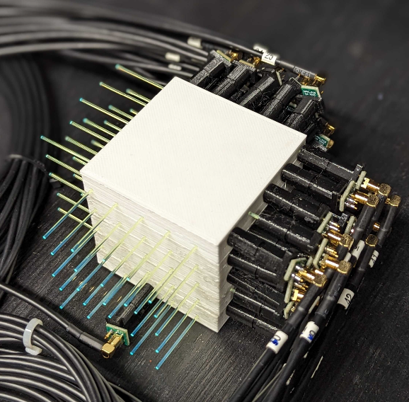
The voxel SuperCube, obtained using the FIM method without the need of post-processing or additional steps, is shown in Fig. 3. It was instrumented with WLS fibers that capture and guide the scintillation light produced by charged particles in single cubes towards coupled silicon photomultipliers (SiPM), which count the number of photons impinging on their active surface. The instrumented detector is shown in Fig. 4. More details can be found in Sec. IV.3.
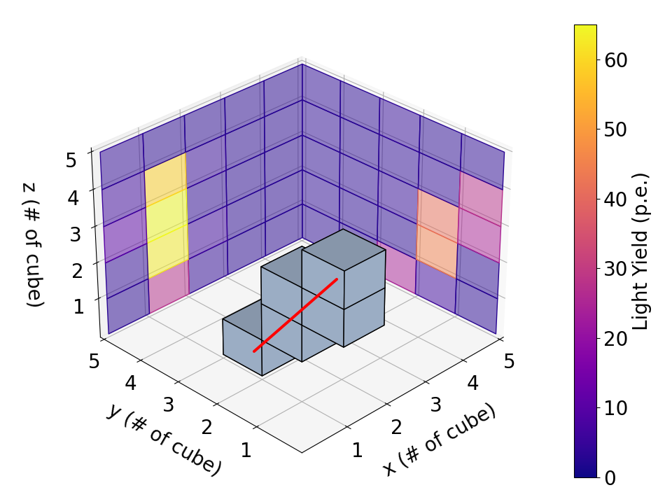
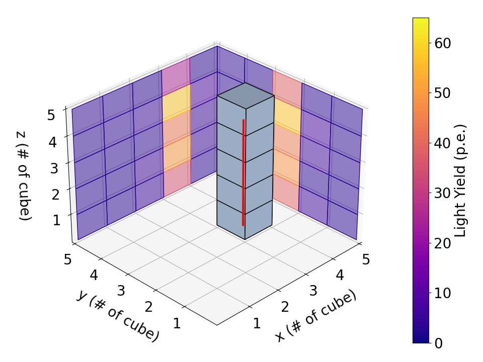
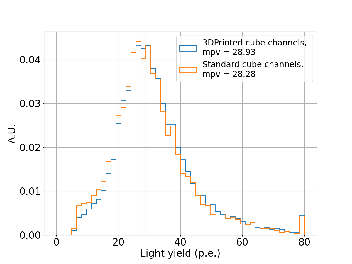
The response of the SuperCube was characterised with cosmic particles in terms of single-cube scintillation light yield and cube-to-cube scintillation light crosstalk, which are the main parameters that determine the detector performance in terms of particle tracking, identification and calorimetry. Cosmic particles entering the prototype from the top side and exiting through the bottom were selected for the analysis. Being mostly minimum ionizing particles (MIP), their typical energy deposited in PS is approximately 1.8 MeV/cm, which allows to precisely estimate the number of photons detected per unit energy loss. Moreover, with an energy spectrum that spans from a few hundred MeV to several GeV, cosmic particles typically produce through-going tracks in the detector with a very uniform energy deposition. Two selected cosmic particle events are shown in Fig. 4. By measuring the number of PE in all the readout channels and geometrically matching the two detector readout, the 3D track of the particle can be easily reconstructed and the number of scintillation photons, produced in each cube, measured. As shown in Fig. 5, the scintillation light yield of the 3D printed prototype was found to be comparable to that obtained with the one produced by cast polymerization (using the same scintillator composition) in [30]. A most probable value (MPV) of about 29 PE was measured for the 3D printed SuperCube, close to the MPV of the prototype produced with cast polymerization (about 28 PE).
In conclusion, the newly developed FIM method allowed for the production of a monolithic 3D optically-segmented matrix of scintillating cubes measuring each . These cubes were fabricated with accurately placed holes for the insertion of WLS fibers in both the X and Y directions. No post-processing was necessary and the detector could be instrumented with the read out electronics right after the fabrication process was completed. Hence, for the first time, a PS detector capable to track elementary particles and measure their energy loss has been successfully additively manufactured. Experimental tests showed a detection performance comparable to the state of the art detectors produced with traditional manufacturing techniques.
III DISCUSSION
The innovative fabrication process developed recently has made it possible to capture a 3D image of particle interaction using a particle detector that was entirely produced through additive manufacturing for the first time. The development of the FIM method was essential to achieve the improved results described above, as it brought several advantages over FDM and other more standard methods like injection molding or cast polymerization.
The FDM manufactured PS showed a sufficient transparency for centimeter-sized voxels, but the FIM fabricated samples visibly improved the quality by reducing imperfections created by the merger of different deposited lines during the FDM process and the reduction of air bubbles within the PS volume. The improved transparency results from the straight down-to-up filling pattern, which creates a single melt pool that expands and forms the PS structure within the optical reflective frame. Multiple converging melt pools introduce non-uniformities that reduce the transparency of the PS. Additionally, the forming of a cubic-centimeter sized PS cube with FIM needs around 30 seconds, whereas the same structure takes around 5 minutes using FDM fabrication, i.e., about ten times as long. The faster per-unit manufacturing time is crucial when it comes to the production of large volume, highly-segmented particle detectors that can include millions of isolated voxels.
The optical isolation of PS voxels is ensured by the FIM process via the FDM-manufactured reflective frame. This is superior to traditional methods, which requires additional vastly dissimilar fabrication steps, as described in Sec. I. The sequence of different fabrication processes increases the total time and cost of production due to the involvement of multiple manufacturing parties, transportation and dead time between steps.
The geometrical tolerance of the optically isolating frame produced by FIM is improved compared to the particle detector manufactured solely by FDM. This is a result of the introduction of a heat-resistant material that is able to preserve its designed shape during the filling of melted PS, thus creates a distinct boundary between the individual PS voxels. In FDM, both the scintillation and the reflective filament are made of plastics with similar thermal characteristics, which can result in a mixing at the boundary layers between these two materials and also a warping and distortion of the reflective geometry. Although the tolerance cannot be considered as good as the one achievable with injection molding or cast polymerization (better than for plastics), it is worth noting, that it is affected by the type of 3D printed material, the printing strategy and the precision of the machine, which will be improved in future studies.
The largest advantage of the FIM method compared to FDM or more traditional methods is the capability of creating precise, close-fitting holes through the entire particle detector to host WLS fibers. FDM is notorious for producing poor quality small holes in terms of size consistency, shape and surface roughness, which results in a low WLS fiber to PS contact area, especially perpendicularly to the print plane. Injection molding has the capability to create hollow components within the manufactured structure. However, incorporating a white reflector without causing any harm to the pre-existing holes poses a significant challenge. In our next prototypes also a third vertical hole will be added.
In terms of the detection performance, the quantity of scintillation light, collected from the FIM manufactured PS cubes crossed by cosmic particles, is similar to that observed from PS cubes produced with traditional methods like cast polymerization. The cube-to-cube crosstalk at the few-percent level is comparable to that of typical PS detectors and is low enough to provide unambiguous 3D particle tracking.
The light crosstalk is about four times higher than with the cast polymerization prototype, due to the higher wall transmittance. Hence, one would expect an approximately 20% lower total light yield. However, this was not observed, as shown in Fig. 5. One may conclude that the additive manufactured PS has an intrinsic light output higher than the one from cast polymerization, but this was not the result of our past work [38, 36]. It is well known, that the light yield of a PS detector can be enhanced by improving the light trapping efficiency of the WLS fibers through the reduction of air gaps, that is the increase of the contact area between the PS and the WLS fibers, whose refractive indices are very similar and thus allows a high transmittance from the scintillation material to the fiber. This can be obtained by using optical grease [41, 42, 43], which is difficult to homogeneously introduce in long, small-diameter holes. Using the FIM method, it was possible to create holes that span the length of the SuperCube of only 100 m larger than the WLS fibers, resulting in a large contact surface between the PS cubes and the fibers. This feature is expected to increase the total light yield and compensate for the light loss from the observed crosstalk.
Overall, the FIM method results in a faster particle detector fabrication by including the shaping of the PS in optically-isolated voxels into an already assembled final detector using one single machine. From here, we see no obstacles that would hinder the viability of this method for large scale particle detector production. Each manufacturing step has consistently yielded satisfactory results.
In conclusion, we have successfully achieved the additive manufacturing of a 3D optically-segmented plastic scintillator detector. To the best of our knowledge, this is the first time such a feat has been accomplished. This detector is capable of both particle tracking and energy loss measurement. It demonstrates a tool that opens new possible concepts of particle detectors characterised by a very fine 3D granularity in very large active volumes, above the tonne-scale. Although not tested in this work, millimeter-sized granularity and bigger units, e.g. or above, are expected to be achieved without problems. We believe that this new technology opens up new possibilities for the future of particle physics experiments. In particular, long-baseline accelerator neutrino oscillations [44, 45, 46, 47] or those searching for new neutrino sterile states via short-baseline oscillations [48, 49, 50, 51, 52, 53] can profit of the developed additive manufacturing process by building very large but finely-segmented scintillator detectors to obtain a large sample of very detailed images of neutrino interactions. Moreover, the developed production method will allow to easily build highly-performing fine-granularity electromagnetic or hadronic sampling calorimeters, enabling high-resolution particle flow analysis and fulfill the requirements of future collider experiments [22, 54]. FIM can be performed with various types of filaments, where the white reflector could be covered by an additional layer made of heavier nuclei or doped material. Finally, large-volume 3D detector geometries, made possible by the FIM process, can allow for a high-efficiency detection of fast neutrons with a precise measurement of their time of flight, thanks to the large content of hydrogen in PS and its short decay time [19, 26]. This is of fundamental importance for next generation neutrino physics experiments, providing constraints on leading systematic uncertainties [25, 55, 24, 56].
IV METHODS
IV.1 Particle Detector Geometry
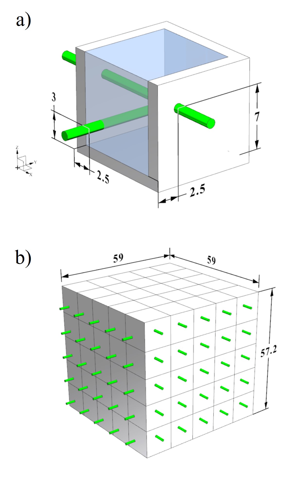
The overlaying structure of particle detector is a cuboid that consists of smaller, cube-shaped detection-units called voxels. One voxel consists of three elements: a PS volume for visible light production; a reflective frame with a wall thickness of 1.5 mm in vertical and 1.2 mm in horizontal plane direction, enclosing the PS to entrap the light in the unit; and two perpendicularly arranged WLS fibers in the horizontal plane with the coordinates (X = 2.5 mm, Z = 3 mm) in Y-direction and (Y = 2.5 mm, Z = 7 mm) in X-direction that absorb the light from the PS, shift its wavelength such that the event can be read-out by an external system connected to the fibers (see Fig. 6 a and Sec. IV.3 for details). The prototype of the “SuperCube” detector consists of 125 detection units arranged in a configuration, resulting in total dimensions of 59 mm in width and 57.2 mm in height, as illustrated in Fig. 6 b.
IV.2 Particle detector fabrication
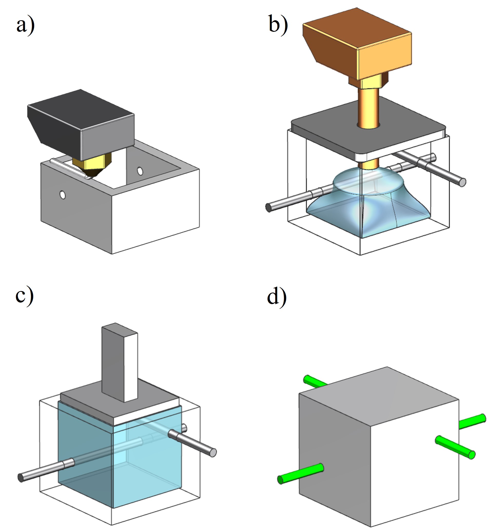
The SuperCube was produced in two separate processes; the fabrication of a matrix layer of an optically reflective frame and the forming of the PS, each using a different mechanical setup. The two production steps were alternated to build a layer-by-layer three-dimensional SuperCube. The reflective frame with holes for the WLS fibers was manufactured via FDM without the use of support structure (Fig. 7 a). The PS was formed in three sub-processes. First, metal rods were placed through the holes to create circular voids for the WLS fibers to be inserted, then the square-shaped volume was rapidly filled in a bottom-to-top motion with a customized extrusion setup combined with a pressurised plate to keep the melt constrained in the cavity (Fig. 7 b) and thirdly, a heated punch was pressed on top of the PS to plane its surface such that the next matrix-layer could be fabricated on top of it (Fig. 7 c). Finally, the top of the voxel was closed by a top layer and the WLS fibers were inserted through the already manufactured holes (Fig. 7 d).
IV.2.1 Reflective Frame Fabrication
The reflective shell was manufactured via FDM using a F430 from Creatbot [57]. In FDM, a polymer string is processed through an extrusion system, which is divided into a cold and hot zone, enabling the distribution of the material with a predetermined temperature and shape. The role of the cold zone is to push the filament with the appropriate speed through feeding tubes into the hot zone, using a motor-controlled gear and roller structure. In this part of the extrusion procedure, the machine temperature must be below the glass transition temperature of the polymer-in-fabrication, otherwise premature softening of the string leads to an increase in friction with the feeding tubes, followed by clogging and system failure. The purpose of the hot zone is to rapidly melt the low thermally conductive material through a metal heat block kept at a polymer specific temperature, such that it can be distributed via an extrusion nozzle into the desired shape. The link between both zones is the heat break, a thin circular tube, which acts as a thermal resistor. It prohibits the heat from creeping from the hot into the cold zone, thus establishing a working temperature in both areas of the extrusion system.
A 1.75 mm polycarbonate-polytetrafluoroethylene-blend (PC-PTFE) filament from Rosa3D filaments [58]
was used for the frame fabrication. This material provided the required combination of good optical reflectivity to contribute to the performance of hte detector and high thermal resistance to ensure the dimensional integrity of the geometry during the forming of the PS.
The structure was printed with a nozzle temperature of 280°C, a bed temperature of 115°C for the first matrix layer and a chamber temperature of 55°C to reduce the risk of warping. After the first filling cycle, the bed temperature was set to 75°C at all time to avoid permanently turning the scintillation material opaque, as was observed in previous studies [38]. The layer height was set to 0.2 mm, the print speed at 2000 mm/min, and cooling was only enabled during the layers that incorporated circular holes to ensure accurate round geometries without the use of support structure. In FDM, the thickness of horizontally-printed walls (parallel to the print bed) is very close to the designed value and was not further investigated. However, 20 thickness measurements of vertically-printed walls (perpendicular to the print bed) were taken using a caliper to show the accuracy and precision of this manufacturing step.
IV.2.2 Plastic scintillator forming
The PS fabrication consisted of three sub-objectives: maximizing the performance of the particle detector, access to an event read-out using WLS fibers in two directions (X, Y) and the preparation of the matrix-layer-in-fabrication for an additional matrix-layer to be built on top.
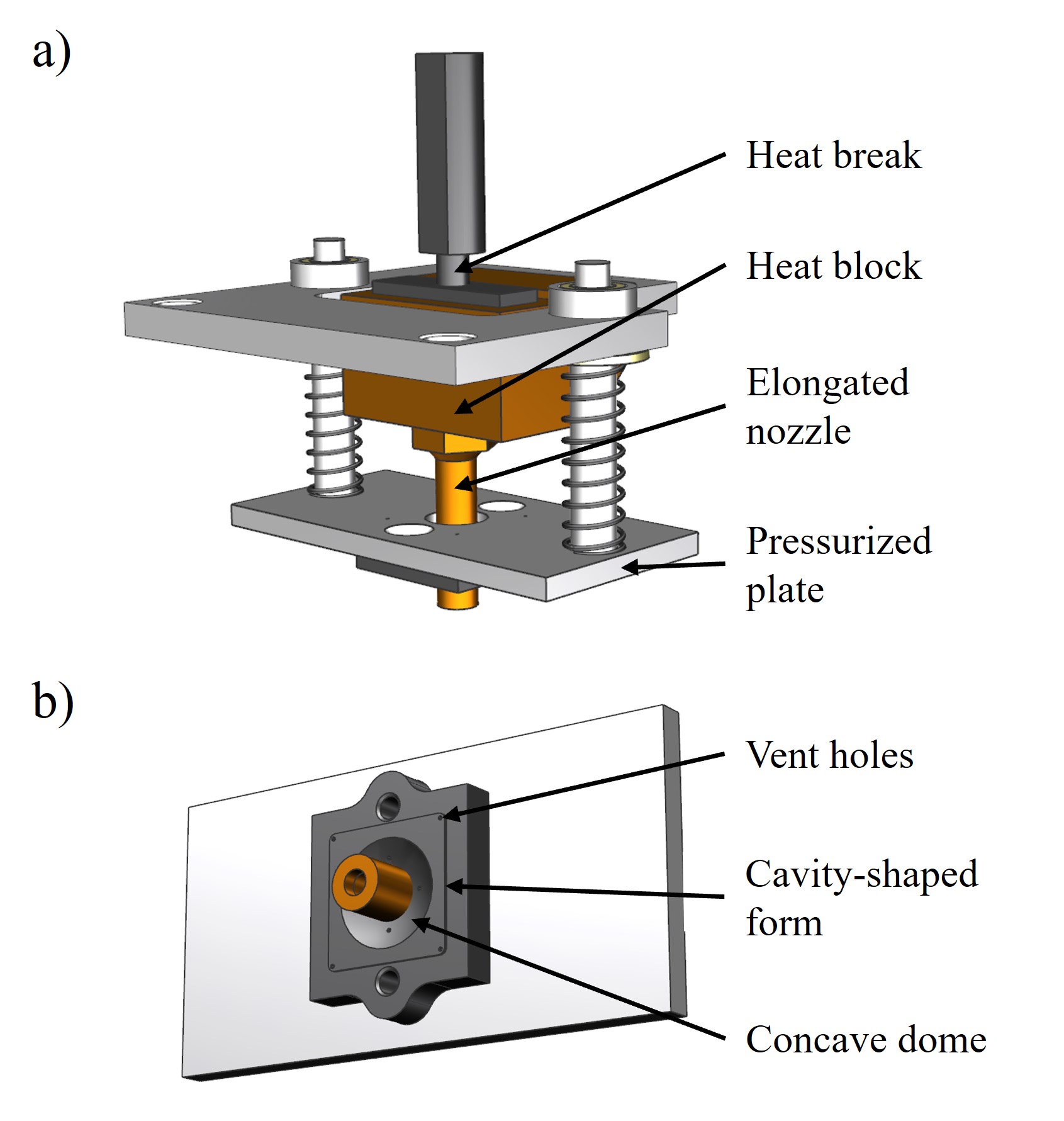
To maximize the particle detector performance, the PS needed to be transparent and have a high fill factor throughout the voxel to increase the active material, and around the metal rods to have a large contact surface between the scintillation material and the WLS fibers for a better light capture efficiency. The fill density is dependent, besides the viscosity of the polymer, on the magnitude of the mass flow rate exiting the nozzle. When increased, the system distributes the melt within the cavity with more energy, pushing the material towards the boundaries with more pressure. This shortens the distribution time of the melt without the polymer being able to cool down and recrystallize before it has reached the outer walls of the reflective shell. An even distribution of scintillation material within the entire cavity shall be achieved by an elongated extrusion nozzle that could reach the bottom of the reflective shell. The liquid polymer was deposited in vertical bottom-to-top movement, creating a single blob, wherefrom the melt spread towards the boundaries. At the top, a spring-loaded, polished, stainless steel plate constrained the melt pool within the cavity (Fig. 8 a). The plate included a hole for the nozzle to move freely up and down, vent holes for air to escape during voxel-filling and a concave dome for a temporarily overfill that compensated for an ensuing material shrinkage (Fig. 8 b).
A CFD analysis using ANSYS Fluent was performed to determine material requirements of the melting components: material of heat block and extrusion nozzle, geometry and material of the heat break and the feeding tube of the filament; and the process parameters heat block temperature and extrusion speed (Fig.9 a).
These process elements were balanced to attain a PS outflow temperature at the nozzle orifice of around 230°C to preserve the scintillation properties established in [36, 38]; to reach the maximum possible material throughput velocity in order to obtain a high fill density of the PS volume by more forcefully spreading the melted polymer throughout the reflective cavity before it solidifies, which is achieved by elevating the heat block temperature (above the usual working temperature) such that the PS is melted to its core at the exit point; and to simultaneously handle the increased heat creep from the high temperature heat block towards the whole extrusion system, which could lead to clogging followed by the failure of the entire injection process.
The discretization of the model concluded in 321,545 nodes with a maximum polymer mesh size of 0.25 mm, a surface mesh size between one and two millimeters, three boundary layers between solid and fluid regions and a volume mesh filled by polyhedra (Fig. 9 b).
Using the discretized model, the following components were determined: the filament-feeding-tube material and the heat break tube-thickness and material, both elements simulated for their heat shielding capabilities; the heat block material and temperature and the nozzle material, both responsible for the melting of the PS. The simulation was based on a laminar flow energy model using a pressure-based transient solver. The surrounding temperature (chamber temperature of the FDM printer) was set to 50°C, the circular cut-out in the heat block was set to a process temperature, simulating an FDM cartridge heater, and the polymer inlet velocity was varied to determine its maximum possible value. Table 1 lists the investigated materials for each extrusion component to achieve a maximal material throughput. The heat break is the essential element in the whole extrusion system because of its shielding function of the cold zone components from the heat creep by the heat block, thus guaranteeing a failure free process. The performance of the manufactured heat break based on the CFD analysis was measured with type “k” thermocouple from the manufacturer Fluke and compared to the commercially available model.
| Extrusion component | Materials |
| Polymer | Polystyrene |
| Feeding tube | Stainless steel, PEEK |
| Heat break | Stainless steel |
| Heat break to heat block coupling | Stainless steel, brass, copper |
| Heat block | Stainless steel, brass, copper |
| Nozzle | Stainless steel, brass, copper |
IV.3 Detector setup and analysis method for cosmic data
The SuperCube was instrumented with fifty readout channels, twenty-five on each view, as shown in Fig. 4.
Kuraray Y11 double-cladding 1 mm diameter WLS fibers [40] along the orthogonal X and Y directions allow to uniquely identify the cubes crossed by a charged particle.
WLS fibers absorb the blue light produced by the PS cube and isotropically emit photons in the green wavelength inside their core. The different refractive index of the outer cladding geometrically traps and guides the photons towards the SiPMs, thanks to an attenuation length of more than 4 meters.
Hamamatsu Multi-Pixel Photon Counters (MPPCs) S13360-1325CS [59] were coupled with individual WLS fibers, on one of the two ends.
The operating voltage was set to the one recommended by the supplier for each MPPC.
The coupling was ensured by black 3D printed optical connectors and enhanced by fixing the WLS fiber with EJ-500 optical glue [60] and pushing the MPPC toward the polished fiber end with a soft black foam acting like a spring.
With a nominal photodetection efficiency of 25%, the analogue charge signal of each MPPC is proportional, to the first order, to the number of photons produced in the PS cubes crossed by the corresponding WLS fiber.
The charge analogue signal of each MPPC is collected with micro-coaxial cables and read out by one CAEN FERS DT5202 front-end (FE) board [61], used to digitize the signal.
The charge value corresponding to the highest signal peak of each independent channel is measured and converted to analogue-to-digital converter (ADC) units.
Then, from the measured number of ADC units, the number of photoelectrons (PE), i.e., the primary electrons originated via photoelectric effect by the visible photons impinging on the MPPC active area, is computed.
Such conversion was obtained with a large data sample collected by exposing the prototype to a radioactive source. The data could show a clear multi-peak structure, each one corresponding to a different number of PEs.
The MPPC gain could be extracted as the distance between adjacent peaks in units of ADC per PE
with a multi-Gaussian distribution fit
and the position of the first three peaks could be obtained.
Then, the peak positions were fitted with a linear function to extract the gain and pedestal.
The above explained procedure was repeated for every channel.
The different gains were found to be relatively uniform around 50 ADC/PE.
Examples of detected cosmic particles can be found in Fig. 4.
The performance of the SuperCube produced with FIM was compared with a reference 2D matrix of cubes produced with injection molding. It consisted of a single layer of optically-isolated PS cubes, thus a geometry analogous to the SuperCube but two dimensional.
In the same way as for the SuperCube, both orthogonal views of the reference sample were read out with
Kuraray Y11 WLS fibers, coupled with the same type of MPPC following the same procedure as described above.
A more detailed description of the reference prototype as well as of its particle detection performance can be found in [30].
The reference prototype was placed on top of the SuperCube and, read out with the same CAEN FERS DT5202 board, was used to trigger the cosmic particles and compare the light yield and crosstalk with the one of the SuperCube.
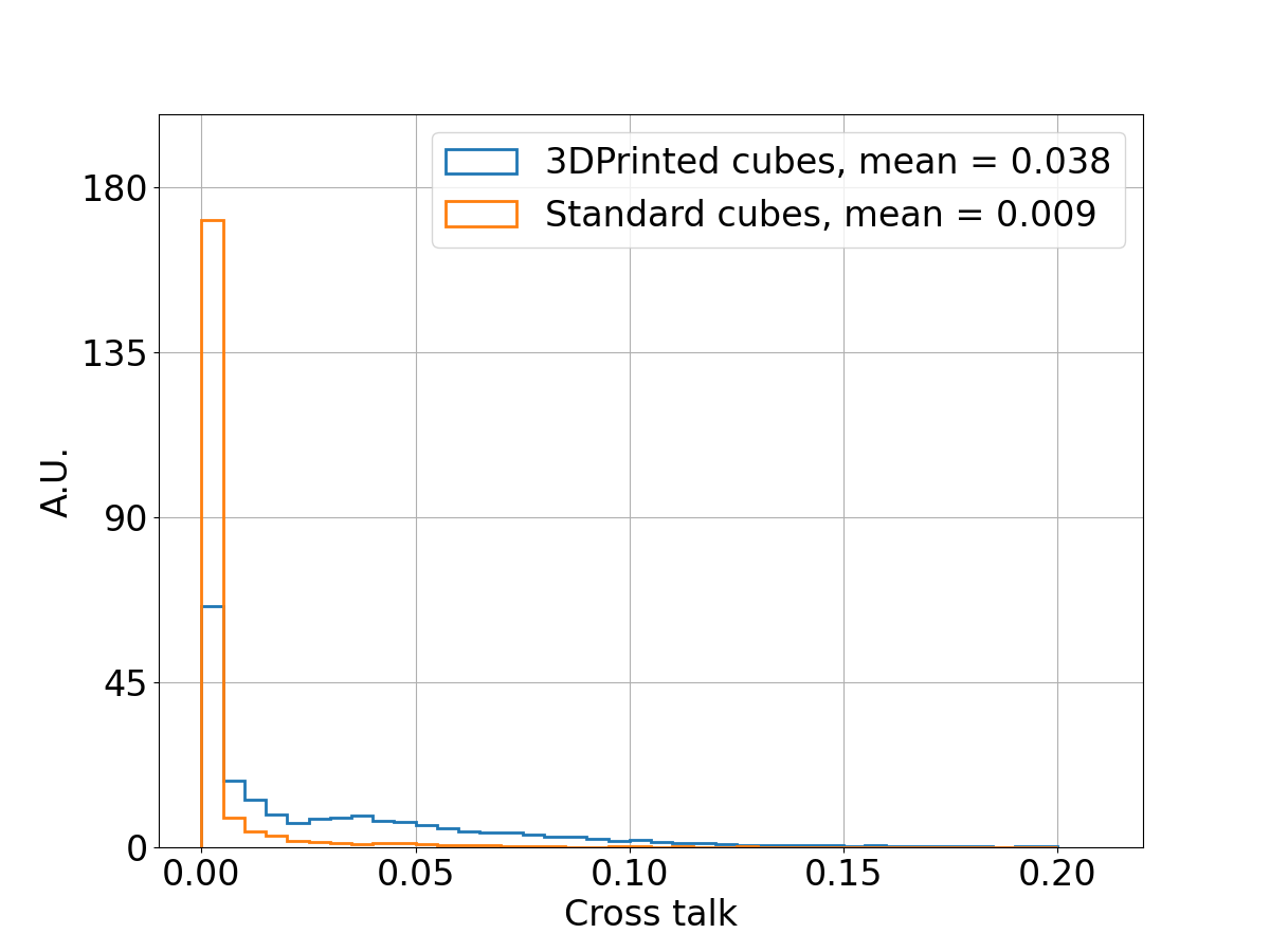
Both the FIM and the injection molding prototypes were characterised by analyzing cosmic particle events and the respective light yield and crosstalk were compared. A total of about 63 hours cosmic data was collected. Typical cosmic events are minimum ionising particles, crossing the prototype every few seconds with an expected energy loss in PS of about 1.8 MeV/cm. Given their angular distribution, approximately equal to where is the azimuth angle, the most common signature consists to the one of a vertical MIP leaving a track that starts from the top layer (the reference prototype) and ends at the bottom layer of the SuperCube, as shown in Fig. 4. The track 3D hits were reconstructed layer by layer, by determining the XY coordinate with the maximum light yield channel in both views. In each electronic channel a threshold of 500 ADC, i.e. about 10 PE, was applied. After the track reconstruction, a data set containing only vertical tracks, i.e. crossing both the reference prototype and the SuperCube in the same column of cubes, was selected to have a particle path length of about 1 cm in each PS cube, hence a comparable energy loss. In Fig. 5, a scintillation light yield of about 29 PE per cube is shown for both the SuperCube and the reference sample. The cube-to-cube light crosstalk was derived from the light yield ratio between neighboring channels within the same layer perpendicular to the track direction. As shown in Fig. 5, a slightly higher crosstalk was measured for the SuperCube . However, it remained constrained at the few % level, thus acceptable for particle tracking and calorimetry measurements.
V Data availability
VI Code availability
References
- Schorr and Torney [1950] M. G. Schorr and F. L. Torney, Phys. Rev. 80, 474 (1950).
- Betancourt et al. [2017] C. Betancourt, A. Blondel, R. Brundler, A. Daetwyler, Y. Favre, D. Gascon, S. Gomez, A. Korzenev, P. Mermod, E. Noah, N. Serra, D. Sgalaberna, and B. Storaci, JINST 12 (11), P11023, arXiv:arXiv:1709.08972 [physics.ins-det] .
- Korzenev et al. [2022] A. Korzenev et al., JINST 17 (01), P01016, arXiv:2109.03078 [physics.ins-det] .
- Amaudruz et al. [2012] P.-A. Amaudruz, M. Barbi, D. Bishop, N. Braam, D. Brook-Roberge, S. Giffin, S. Gomi, P. Gumplinger, K. Hamano, N. Hastings, S. Hastings, R. Helmer, R. Henderson, K. Ieki, B. Jamieson, I. Kato, N. Khan, J. Kim, B. Kirby, P. Kitching, A. Konaka, M. Lenckowski, C. Licciardi, T. Lindner, K. Mahn, E. Mathie, C. Metelko, C. Miller, A. Minamino, K. Mizouchi, T. Nakaya, K. Nitta, C. Ohlmann, K. Olchanski, S. Oser, M. Otani, P. Poffenberger, R. Poutissou, J.-M. Poutissou, W. Qian, F. Retiere, R. Tacik, H. Tanaka, P. Vincent, M. Wilking, S. Yen, and M. Yokoyama, Nucl. Instrum. Meth. A 696, 1 (2012), arXiv:arXiv:1204.3666 [physics.ins-det] .
- Aliaga et al. [2014] L. Aliaga et al. (MINERvA), Nucl. Instrum. Meth. A 743, 130 (2014), arXiv:arXiv:1305.5199 [physics.ins-det] .
- Michael et al. [2008] D. G. Michael et al. (MINOS), Nucl. Instrum. Meth. A 596, 190 (2008), arXiv:0805.3170 [physics.ins-det] .
- Allan et al. [2013] D. Allan, C. Andreopoulos, C. Angelsen, G. J. Barker, G. Barr, S. Bentham, I. Bertram, S. Boyd, K. Briggs, R. G. Calland, J. Carroll, S. L. Cartwright, A. Carver, C. Chavez, G. Christodoulou, J. Coleman, P. Cooke, G. Davies, C. Densham, F. D. Lodovico, J. Dobson, T. Duboyski, T. Durkin, D. L. Evans, A. Finch, M. Fitton, F. C. Gannaway, A. Grant, N. Grant, S. Grenwood, P. Guzowski, D. Hadley, M. Haigh, P. F. Harrison, A. Hatzikoutelis, T. D. J. Haycock, A. Hyndman, J. Ilic, S. Ives, A. C. Kaboth, V. Kasey, L. Kellet, M. Khaleeq, G. Kogan, L. L. Kormos, M. Lawe, T. B. Lawson, C. Lister, R. P. Litchfield, M. Lockwood, M. Malek, T. Maryon, P. Masliah, K. Mavrokoridis, N. McCauley, I. Mercer, C. Metelko, B. Morgan, J. Morris, A. Muir, M. Murdoch, T. Nicholls, M. Noy, H. M. O'Keeffe, R. A. Owen, D. Payne, G. F. Pearce, J. D. Perkin, E. Poplawska, R. Preece, W. Qian, P. Ratoff, T. Raufer, M. Raymond, M. Reeves, D. Richards, M. Rooney, R. Sacco, S. Sadler, P. Schaack, M. Scott, D. I. Scully, S. Short, M. Siyad, R. Smith, B. Still, P. Sutcliffe, I. J. Taylor, R. Terri, L. F. Thompson, A. Thorley, M. Thorpe, C. Timis, C. Touramanis, M. A. Uchida, Y. Uchida, A. Vacheret, J. F. V. Schalkwyk, O. Veledar, A. V. Waldron, M. A. Ward, G. P. Ward, D. Wark, M. O. Wascko, A. Weber, N. West, L. H. Whitehead, C. Wilkinson, and J. R. Wilson, JINST 8, P10019, arXiv:arXiv:1308.3445 [physics.ins-det] .
- Joram et al. [2015] C. Joram, U. Uwer, B. D. Leverington, T. Kirn, S. Bachmann, R. J. Ekelhof, and J. Müller, LHCb Scintillating Fibre Tracker Engineering Design Review Report: Fibres, Mats and Modules (2015).
- Förster [1948] T. Förster, Annalen der Physik 437, 55 (1948), https://onlinelibrary.wiley.com/doi/pdf/10.1002/and p.19484370105 .
- Birks [1960] J. B. Birks, IRE Transactions on Nuclear Science 7, 2 (1960).
- BIRKS [1964] J. BIRKS, in The Theory and Practice of Scintillation Counting, International Series of Monographs in Electronics and Instrumentation, edited by J. BIRKS (Pergamon, 1964) pp. 39–67.
- [12] C. Harper and E. Petrie, In Plastics Materials and Processes: A Concise Encyclopedia (2003), John Wiley & Sons.
- Atoian et al. [2004] G. S. Atoian, V. V. Issakov, O. V. Karavichev, T. L. Karavicheva, A. A. Poblaguev, and M. E. Zeller, Nucl. Instrum. Meth. A 531, 467 (2004), arXiv:physics/0310047 .
- Appel et al. [2002] R. Appel et al. (E865), Nucl. Instrum. Meth. A 479, 349 (2002).
- Thevenin et al. [1980] J. Thevenin, L. Allemand, E. Locci, P. Micolon, S. Palanque, and M. Spiro, Nuclear Instruments and Methods 169, 53 (1980).
- Pla-Dalmau et al. [2001] A. Pla-Dalmau, A. D. Bross, and K. L. Mellott, Nuclear Instruments and Methods in Physics Research Section A: Accelerators, Spectrometers, Detectors and Associated Equipment 466, 482 (2001).
- Kudenko et al. [2001] Y. G. Kudenko, L. S. Littenberg, V. A. Mayatsky, O. V. Mineev, and N. V. Ershov, Nucl. Instrum. Meth. A 469, 340 (2001).
- Abreu et al. [2018] Y. Abreu et al. (SoLid), JINST 13 (09), P09005, arXiv:1806.02461 [physics.ins-det] .
- Blondel et al. [2018] A. Blondel, F. Cadoux, S. Fedotov, M. Khabibullin, A. Khotjantsev, A. Korzenev, A. Kostin, Y. Kudenko, A. Longhin, A. Mefodiev, P. Mermod, O. Mineev, E. Noah, D. Sgalaberna, A. Smirnov, and N. Yershov, Journal of Instrumentation 13 (02), P02006.
- Mineev et al. [2019] O. Mineev, A. Blondel, Y. Favre, S. Fedotov, A. Khotjantsev, A. Korzenev, Y. Kudenko, A. Mefodiev, E. Noah, D. Sgalaberna, and S. Suvorov, Nuclear Instruments and Methods in Physics Research Section A: Accelerators, Spectrometers, Detectors and Associated Equipment 923, 134–138 (2019).
- Blondel et al. [2020] A. Blondel, M. Bogomilov, S. Bordoni, F. Cadoux, D. Douqa, K. Dugas, T. Ekelof, Y. Favre, S. Fedotov, K. Fransson, R. Fujita, E. Gramstad, A. K. Ichikawa, S. Ilieva, K. Iwamoto, C. Jesus-Valls, C. K. Jung, S. P. Kasetti, M. Khabibullin, A. Khotjantsev, A. Korzenev, A. Kostin, Y. Kudenko, T. Kutter, T. Lux, L. Maret, T. Matsubara, A. Mefodiev, A. Minamino, O. Mineev, G. Mitev, M. Nessi, L. Nicola, E. Noah, S. Parsa, G. Petkov, F. Sanchez, D. Sgalaberna, W. Shorrock, K. Skwarczynski, S. Suvorov, A. Teklu, R. Tsenov, Y. Uchida, G. Vankova-Kirilova, N. Yershov, M. Yokoyama, J. Zalipska, Y. Zou, and W. Zurek, JINST 15 (12), P12003, arXiv:arXiv:2008.08861 [physics.ins-det] .
- Andreev et al. [2006] V. Andreev et al., Nucl. Instrum. Meth. A 564, 144 (2006).
- Abreu et al. [2017] Y. Abreu et al. (SoLid), JINST 12 (04), P04024, arXiv:1703.01683 [physics.ins-det] .
- Munteanu et al. [2020] L. Munteanu, S. Suvorov, S. Dolan, D. Sgalaberna, S. Bolognesi, S. Manly, G. Yang, C. Giganti, K. Iwamoto, and C. Jesús-Valls, Phys. Rev. D 101, 092003 (2020), arXiv:arXiv:1912.01511 [physics.ins-det] .
- Manly et al. [2021] S. Manly, M. Kordosky, and O. behalf of the DUNE Collaboration, Instruments 5, 10.3390/instruments5040031 (2021).
- Gwon et al. [2023] S. Gwon et al., Phys. Rev. D 107, 032012 (2023), arXiv:2211.17037 [hep-ex] .
- Agarwal et al. [2023] A. Agarwal et al., Phys. Lett. B 840, 137843 (2023), arXiv:2207.02685 [physics.ins-det] .
- Abe et al. [2019] K. Abe et al. (T2K), T2K ND280 Upgrade - Technical Design Report (2019), arXiv:1901.03750 [physics.ins-det] .
- Fedotov et al. [2022] S. Fedotov, A. Dergacheva, A. Filik, M. Khabibullin, A. Khotjantsev, Y. Kudenko, Y. Kudenko, O. Mineev, and N. Yershov, J. Phys. Conf. Ser. 2374, 012106 (2022), arXiv:2111.07305 [physics.ins-det] .
- Boyarintsev et al. [2021] A. Boyarintsev et al., JINST 16 (12), P12010, arXiv:2108.11897 [physics.ins-det] .
- Newman et al. [2015] S. T. Newman, Z. Zhu, V. Dhokia, and A. Shokrani, CIRP Annals 64, 467 (2015).
- [32] FDM Technology, About Fused Deposition Modeling (copyright by Stratasys), http://www.stratasys.com/3d-printers/technologies/fdm-technology.
- [33] M. Groover, Fundamentals of modern manufacturing: materials, processes, and systems. John Wiley & Sons, Inc, 2013.
- Bellini and Güçeri [2020] A. Bellini and S. Güçeri, Rapid Prototyping Journal 9, 252 (2020).
- Mishnayot et al. [2014] Y. Mishnayot, M. Layani, I. Cooperstein, S. Magdassi, and G. Ron, Review of Scientific Instruments 85, 085102 (2014), https://doi.org/10.1063/1.4891703 .
- Berns et al. [2020] S. Berns, A. Boyarintsev, S. Hugon, U. Kose, D. Sgalaberna, A. De Roeck, A. Lebedynskiy, T. Sibilieva, and P. Zhmurin, JINST 15 (10), 10, arXiv:2011.09859 [physics.ins-det] .
- Hamel and Lebouteiller [2020] M. Hamel and G. Lebouteiller, Journal of Applied Polymer Science 137, 48724 (2020), https://onlinelibrary.wiley.com/doi/pdf/10.1002/app.48724 .
- Berns et al. [2022] S. Berns et al. (3DET), JINST 17 (10), P10045, arXiv:2202.10961 [physics.ins-det] .
- Artikov et al. [2005] A. Artikov, J. Budagov, I. Chirikov-Zorin, D. Chokheli, M. Lyablin, G. Bellettini, A. Menzione, S. Tokar, N. Giokaris, and A. Manousakis-Katsikakis, Nucl. Instrum. Meth. A 555, 125 (2005).
- [40] Kuraray catalogue - plastic scintillating fibers, http://kuraraypsf.jp/psf/ws.html.
- Artikov et al. [2017] A. M. Artikov et al., Phys. Part. Nucl. Lett. 14, 139 (2017), arXiv:1604.02286 [physics.ins-det] .
- Artikov et al. [2019] A. Artikov et al., Nucl. Instrum. Meth. A 930, 87 (2019), arXiv:1711.11393 [physics.ins-det] .
- Artikov et al. [2016] A. Artikov et al., JINST 11 (05), T05003, arXiv:1604.02260 [physics.ins-det] .
- Abe et al. [2017] K. Abe et al. (T2K), Phys. Rev. Lett. 118, 151801 (2017), arXiv:arXiv:1701.00432 [hep-ex] .
- Abe et al. [2020] K. Abe et al. (T2K), Nature 580, 339 (2020), [Erratum: Nature 583, E16 (2020)], arXiv:arXiv:1910.03887 [hep-ex] .
- Acero et al. [2022] M. A. Acero et al. (NOvA), Phys. Rev. D 106, 032004 (2022), arXiv:2108.08219 [hep-ex] .
- Abe et al. [2018] K. Abe et al. (Hyper-Kamiokande), Hyper-Kamiokande Design Report (2018), arXiv:arXiv:1805.04163 [physics.ins-det] .
- Abreu et al. [2021] Y. Abreu et al. (SoLid), JINST 16 (02), P02025, arXiv:2002.05914 [physics.ins-det] .
- Andriamirado et al. [2021] M. Andriamirado et al. (PROSPECT), Phys. Rev. D 103, 032001 (2021), arXiv:2006.11210 [hep-ex] .
- Almazán et al. [2020] H. Almazán et al. (STEREO), Phys. Rev. D 102, 052002 (2020), arXiv:1912.06582 [hep-ex] .
- Atif et al. [2022] Z. Atif et al. (RENO, NEOS), Phys. Rev. D 105, L111101 (2022), arXiv:2011.00896 [hep-ex] .
- Alekseev et al. [2018] I. Alekseev et al. (DANSS), Phys. Lett. B 787, 56 (2018), arXiv:1804.04046 [hep-ex] .
- Serebrov et al. [2021] A. P. Serebrov et al., Phys. Rev. D 104, 032003 (2021), arXiv:2005.05301 [hep-ex] .
- Repond et al. [2018] J. Repond et al. (CALICE), JINST 13 (12), P12022, arXiv:1809.03909 [physics.ins-det] .
- Cai et al. [2023] T. Cai et al. (MINERvA), Nature 614, 48 (2023).
- Baudis et al. [2023] N. Baudis, S. Dolan, D. Sgalaberna, S. Bolognesi, L. Munteanu, and T. Dieminger, Longitudinal kinematic imbalances in (anti-)neutrino interactions for improved measurements of nuclear removal energies and the axial vector form factor (2023), arXiv:2310.15633 [hep-ph] .
- [57] CreatBot F430, https://www.creatbot.com/en/F430.html.
- [58] Rosa3D filament, https://rosa3dfrance.fr.
- ham [2022] MPPC (multi-pixel photon counter) S13360 series, Hamamatsu (2022), accessed 9th of June 2023.
- [60] Eljen Technology - EJ-500 optical glue, https://eljentechnology.com/products/accessories/ej-500.
- [61] CAEN FERS DT5202, https://www.caen.it/products/dt5202/.
VII Acknowledgements
Part of this work was supported by the SNF grant PCEFP2_203261, Switzerland.
VIII Author contributions
D.S. and T.W. conceived the additive manufacturing method.
T.W. implemented the method by designing and making the 3D printer components, tuning the 3D printer parameters and producing the final 3D printed sample.
D.S. supervised the implementation process.
U.K. and B.L. built the experimental setup for cosmic particle data taking.
B.L. ran the particle detection experiment and performed the data analysis.
U.K. and D.S. supervised the data taking and the data analysis.
Also A.Ru. supervised the data analysis.
A.B. and T.S. produced the scintillator filament used for the 3D printed prototype.
S.B., E.B and S.H. provided some of the necessary equipment and discussed the results.
All the authors, part of the 3D printed DETector (3DET) R&D collaboration, discussed and commented on the manuscript.
IX Competing interests
The authors declare no competing interests.