Efficient Synthesis of Passively Loaded Finite Arrays for Tunable Anomalous Reflection
Abstract
A design methodology for planar loaded antenna arrays is proposed to synthesize a perfect anomalous reflection into an arbitrary direction by optimizing the scattering characteristics of passively loaded array antennas. It is based on efficient and accurate prediction of the induced current distribution and the associated scattering for any given set of load impedances. For a fixed array of finite dimensions, the deflection angles can be continuously adjusted with proper tuning of each load. We study and develop anomalous reflectors as semi-finite (finite × infinite) and finite planar rectangular arrays comprising printed patches with a subwavelength spacing. Anomalous reflection into an arbitrary desired angle using purely reactive loads is numerically and experimentally validated. Owing to the algebraic nature of load optimization, the design methodology may be applied to the synthesis of large-scale reflectors of practical significance.
Index Terms:
Anomalous reflector, receiving antennas, aperiodic loadings, reconfigurable intelligent surface (RIS), far-field scattering, reflectarray.I Introduction
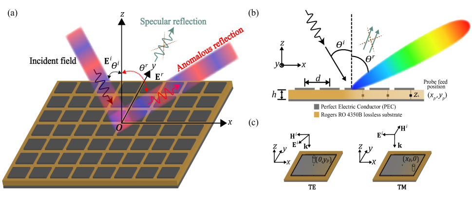
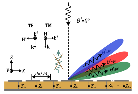
Areconfigurable Intelligent Surface (RIS) is an engineered surface structure to manipulate electromagnetic (EM) waves upon reflection/transmission, aiming for versatile functionalities [1, 2, 3] in 6G wireless networks by enhancing coverage and overcoming challenges associated with non-line-of-sight scenarios. In particular, an RIS can scatter the incident power into a non-specular direction by breaking the law of reflection for a homogeneous reflecting surface, realizing an anomalous reflection, as illustrated in Fig. 1. An anomalous reflector encompasses a typically planar surface with an ample amount of tunable discrete subwavelength-sized elements that can present reconfigurable properties to re-engineer the electromagnetic (EM) interaction with an incoming wave. Advanced methods to achieve anomalous reflection using periodic metasurfacess [4, 5, 6, 7, 8, 9, 10] and metagratings [11, 12, 13, 14, 15, 16] have been proposed for various applications. Nevertheless, research on modeling and designing highly directive and efficient anomalous reflectors is still evolving. The most challenging problem is to realize continuous scanning of the reflection angle without deteriorating performance.
Pioneering research on anomalous deflection has been based on engineering the reflection phase gradient along the reflector surface, violating the usual reflection law (i.e., the incident and reflection angles are not equal, ). Application of the phased-array principle [17], also formulated as the generalized law of reflection [18], leads to a periodic reflector with a linear reflection phase gradient of the local reflection coefficient. However, the anomalous reflection efficiency of the linear phase-gradient reflectors diminishes gradually with increasing deflection tilts, predominantly due to the impedance mismatch between the incident and reflected plane waves and the associated strong parasitic reflections in unwanted directions.
The most typical approach in modeling anomalous reflectors treats periodic structures because only one period needs to be analyzed and designed. The spatial periodicity forces discrete spectra for waves, described by Floquet modes. For a given set of incidence and reflection angles, the smallest spatial periodicity for supporting them is . The periodicity changes with the angles, not allowing continuous scanning for any periodic reflector with a fixed . Hence, no periodic reflector can continuously scan reflected beams. Traditionally, this difficulty has been addressed using reflectarrays comprising resonant elements having aperiodic loads of a fixed (typically ) geometrical periodicity [19, 20]. Based on the locally periodic approximation (LPA), array element loads are chosen by linearly varying the reflection phase of the corresponding uniform arrays along the reflection plane. This technique is effective for relatively small deflection angles, but the reflection efficiency deteriorates for wide-angle deflections. Not relying on the LPA, design and optimization of the entire reflector using full-wave EM simulations is an option, but it becomes computationally inefficient for electrically large structures. In addition, a reconfigurable anomalous reflector design needs to incorporate tunable components to manipulate the EM properties by external stimuli. One approach is to embed one or more tunable components into each meta-atom to enable multi-functional reconfigurability [21].
Application of tunable anomalous reflectors in practice requires synthesis of electrically large, finite structures incorporating numerous tunable elements. Even for infinite periodic reflectors under a supercell periodicity, optimizing the supercell details for perfect anomalous reflection using full-wave simulations is a computationally demanding task. In alleviating this difficulty, an arithmetic optimization method has been developed using array antenna scattering synthesis for infinite periodic reflectors comprising reactively loaded patch elements in a supercell [9]. In this work, we extend the scattering synthesis approach to finite antenna arrays in 2D and 3D, demonstrating numerically efficient synthesis of finite reflectors having high anomalous reflection efficiencies for all deflection angles.
This article is organized as follows. In Section II, we present the problem configuration and develop the scattering synthesis theory for aperiodically loaded antenna arrays. Subsections therein address the principle and optimization technique for finite antenna arrays. In Section III, we show 2-D finite (semi-finite) arrays with different element spacings, assess the reflection efficiency, and evaluate the numerical efficiency of the optimization. In Section IV, we present optimized finite planar arrays with aperiodic loadings to realize tunable anomalous reflections using purely reactive loads. In Section V, we illustrate the experiment results of the manufactured passive fixed anomalous reflector. Finally, Section VI provides a summary and concluding observations.
II Principle and Methodology of Anomalous Reflector Design
Anomalous reflection into a predetermined nonspecular direction for a large deflection tilt is depicted in Figs. 1(a) and (b). A finite number of metallic patches loaded with lumped loads are etched on a dielectric substrate as a periodic grid in the -plane, at a height above a finite perfect electric conductor (PEC) ground plane. The plane of incidence and reflection is the -plane. An equispaced grid of patches with (generally aperiodic) loads are to be designed where a spacing between radiating elements is . With equally spaced radiating elements, the traditional reflectarray design approach uses a reflection phase distribution that follows the linear phase gradient law. However, it is shown in [9] that a perfect anomalous reflection in a large deflection angle cannot be reached by utilizing a regular loading pattern following the linear reflection phase gradient. Here, we show that anomalous finite reflector structures with aperiodical loadings can scatter the incoming wave from any incidence angle into a arbitrary non-specular direction, avoiding computation-intensive full-wave EM simulations by transferring the load optimization to the circuit network synthesis domain.
In an infinite periodic reflector design, the design goal is to deflect an incoming propagating plane wave into a reflected plane wave in an anomalous direction. For finite arrays subject to a plane-wave illumination, the design goal is to ensure one scattered main beam with a high directivity in the desired direction as illustrated in Fig. 1(b). A high-efficiency reflection into a nonspecular angle entails minimizing the specular reflection from the underlying PEC ground plane for finite structures.
II-A Reception and Scattering Calculation of Aperiodically Loaded Antenna
Let us consider the transmitting and receiving configurations of an antenna, where the reception and scattering properties of the loaded antenna depend on the load connected at the antenna terminals [22, 23]. The total scattered -field, , scattered by an antenna for a particular load impedance, , is the superposition of zero-current scattering and port-current scattering, which can be written as [24]
| (1) |
where is the radiated -field in the transmitting (TX) mode for a unit input current excitation, is the scattered -field when its feed point is open-circuited, and is the load current. The first and second terms on the right side in (1) are often referred to as structural scattering and reradiation components, respectively [25, 24]. This decomposition of the total scattered field is not unique, and the structural scattering is set by the reference load condition. We choose the open-circuit load as the reference. The total scattering can be split in different ways [26, 24].
The scattered field decomposition (1) also applies to the general receiving (RX) antenna array with aperiodic loadings. To design a finite-dimension anomalous reflector, a finite array variant of an isolated antenna scattering [24] or the infinite periodic array scattering [9] can be adopted. In an -element loaded meta-atom array, a complex load terminates the -th meta-atom. While scattering synthesis via (1) can be performed for any incident wave and array configuration, let us focus on plane-wave scattering by a linear array. In an time convention dependence, the finite structure is illuminated by an incident plane wave with an -field
| (2) | ||||
| (3) |
where is the angle of incidence, and is the free-space wavenumber. Via reciprocity, the RX mode parameters are related to to the TX mode scanning in the direction .
In the RX and scattering case, the open-circuit voltage and the load current across the terminals of the loaded RX antenna array take the matrix form, as an extension of the isolated RX antenna case, written as
| (4) | ||||
| (5) |
where is the impedance matrix of the antenna array (a full matrix with elements representing self and mutual impedances) and is a diagonal matrix with along the diagonal. The column vector has the vector effective height [27] for the -th antenna as its -th element, , computed from the TX mode for far-field observation in . The column vector contains all open-circuit voltages at the terminals of the RX array. Its elements are , where the incident field values are taken at the global coordinate origin , as illustrated in Fig. 1(a). The column vector contains all individual load currents at the array ports. Canonical array configurations with available near-zone field distribution expressions allow analytical load port current calculations, such as for 2-D wire arrays [28]. Such an approach is not that straightforward for arbitrary arrays, because usually the elements lack analytical formulations for near-zone fields. In this case, load current calculation using the RX antenna theory is useful.
It is essential to perform a set of preliminary simulation studies to prepare for global numerical optimization to attain the scattered beam in the anomalous direction by optimizing ’s. The network impedance matrix is found using a TX simulation for mutual coupling between ports. TX simulations also provide the vector effective height for the -th patch element. To find , it should be remembered to enforce by open-circuiting unexcited patch ports. The open-circuit voltages for the element ports can be computed using (4). Alternatively, can be obtained directly using an RX-mode simulation by monitoring the voltage at the open-circuited ports. Numerical studies confirm that the two approaches produce the same values of . Once the preliminary numerical analysis is complete, optimizations of algebraic nature can be carried out to synthesize the desired scattering characteristics. The required preliminary analysis is unique to every array scattering synthesis problem.
In the far-field region of the scattering array, the total secondary -field, , scattered by the array for a particular load impedance matrix, , in a reflection direction given by is evaluated by extending (1) as
| (6) |
where and are the load port current and the vector effective height, respectively, at the -th port. The free-space intrinsic impedance is denoted by , and is the scattered field from the patch array in when all load terminals are open-circuited. Let us limit our attention to anomalous reflection in the -plane, i.e., or . We adopt the bistatic scattering cross-section (SCS) as the metric in assessing the effectiveness of the synthesized loaded array for creating a strong scattered beam in the desired direction. For the loaded array, it is given by [22]
| (7) |
Once , , and are computed and available, we note that can be evaluated in every scattered direction for any set of loads via an algebraic process. It is numerically efficient compared with full-wave simulations. Changing the incident wave direction or polarization requires new evaluation of only.
In addition to arrays of finite dimensions both in the - and -directions, we will also consider arrays that are finite along the -axis and infinite periodic along the -axis (i.e., finite × infinite). For such arrays, anomalous reflection in the -plane will be synthesized. With a subwavelength periodicity and a uniform phase in the -direction, the scattered waves are cylindrical waves instead of spherical waves. In the same manner as in (6), cylindrical wave scattering in the effective 2-D environment can be split into structural and reradiation contributions as
| (8) |
where is the distance from the -axis. Then, the 2-D scattering width, , is [29]
| (9) |
II-B Optimization Methodology
We aim to achieve high-efficiency anomalous reflection using reactive loads only, without any active elements. Optimization of the induced current distribution at the reactive loaded elements intends to redirect all the incident power from any oblique angle into any desired direction. Each reactive load at the antenna terminals is independently varied, resulting in an algebraic optimization over the metasurface. A practical choice for the tunable components for the finite patch arrays is lumped elements (such as varactors or switches) in each unit cell. Another possibility is to use electrically tunable substrate materials [21]. The optimization process can be performed by maximizing in the desired direction by adjusting . For a finite-array reflector design, a bistatic SCS is an appropriate quantity to maximize the scattering in the desired anomalous direction.
In preparation for the optimization, the goal is to maximize the predicted bistatic SCS in (7) to realize perfect anomalous reflection in the desired anomalous direction as the global fitness function. Numerical experiments reveal that it is worth adding constraints designed to suppress unwanted deflections in the specular reflection and other directions as a cost function during reactive load optimizations. These constraints define a multi-objective optimization problem toward finding a globally optimal solution. The multi-objective optimization problem is formulated as follows:
| (10) | ||||||
| s.t. | ||||||
| where | ||||||
Here, is a small positive constant. The azimuth angle is limited to or , as appropriate for a reflection in the -plane. The optimization is performed using the fmincon function in Matlab. The fmincon function is a practical tool for a multi-objective optimization. The optimization converges to find an optimal set of purely reactive load impedances using the objective function to maximize and the additional constraints to minimize.
The optimization process is as follows: First, an initial set of load impedances are selected to initiate the optimization. A set of purely-reactive load values for the meta-atoms are chosen for this purpose, e.g., from the traditional locally periodical approximation in the linear phase-gradient method. Details of the legacy conventional reflectarray method are given in Appendix A. Then, the bistatic SCS is calculated using (7) over a range of as needed. The above step is repeated by updating the purely reactive impedance loads until the termination criterion is satisfied. Finally, we evaluate the angular response in the far zone using the optimized load values. We verify whether the incident power is rerouted to the predetermined anomalous direction, i.e., a near-perfect anomalous deflection is achieved.
III Optimized finite Arrays to realize Perfect Anomalous Reflectors
It is expected that optimization of loads of -periodical arrays will not result in desired nearly perfect performance for any deflection angles, because it is known that realization of desired induced currents in general requires complex (active-lossy) loads [28]. For this reason, we verify the efficiency of the optimization and the performance of the optimized reflectors considering array designs with subwavelength unit cells and aperiodic passive loadings. A subwavelength cell size enables a fine-grained control of the induced current to help focus the scattered wave toward the desired direction [1]. The power efficiency of anomalous reflection for the conventional reflectarray design with a linear phase gradient loading diminishes gradually for large deflection tilts (considerably more than at normal illumination) due to parasitic reflections into unwanted directions [4, 9]. For infinite periodic reflectors, wide-angle anomalous reflector design techniques that do not require supercell-level EM simulation optimizations have been reported, based on spatially continuous surface reactance synthesis [30] and scattering synthesis for infinite periodic loaded arrays [9]. However, these techniques are limited to periodic reflectors.
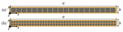
In this section, we present finite-dimension anomalous reflector designs using arithmetic optimization of aperiodic loadings. First, we inspect how many optimization parameters are needed and what sub-wavelength element spacing is required to realize a highly directive non-specular reflection. We need the classical half-wavelength sampling from the Nyquist rate to control and construct the propagating EM spectrum under arbitrary illumination and scattering conditions. However, to fully control amplitudes and phases at all elements, complex-valued load impedances are required. In studies of periodic arrays it was shown that to realize the currents that create desired scattering using only passive elements, twice as many scattering elements are needed [13]. In this study, linear arrays of a spacing and a spacing are designed and compared, while the overall array size is fixed, as illustrated in Fig. 2. This way, the impact of the element spacing on the anomalous reflection characteristics can be inspected. In addition, the performance of the anomalous reflectors is evaluated for both TE- and TM-polarized incident waves.
We begin with determining the dimensions for the single meta-atom as a self-resonant patch under periodic boundary conditions. All numerical simulations have been performed using a commercial software (CST Microwave Studio). A linearly polarized square PEC patch antenna in a unit cell is simulated at a design frequency of 28 GHz to acquire a good impedance match to . The substrate used in all simulations is Rogers RO4350B (neglecting losses) laminate (a relative permittivity ) and a 0.338-mm thickness. The patch dimensions and feeding position data optimized for a - input impedance at resonance at the design frequency are reported in Table I. It is worth mentioning that the self-resonance and especially the - matching condition are used here as conventions, but they are not necessary for a successful design. Next, individual aperiodic loads connected to the patch terminals are optimized following Section II for -periodic arrays. The proposed design technique can be used to synthesize large square or rectangular arrays toward practical applications. However, the design principle and effectiveness can be demonstrated at a reasonable computational cost by using -periodic (-infinite) arrays with one finite and one infinite dimension. Here, the incidence and reflection is limited to the -plane.
| Parameters | spacing | spacing | |
|---|---|---|---|
| Array dimension | |||
| ( mm mm) | |||
| Substrate height () | mm | ||
| Square Patch dimension | mm | mm | |
| Probe position | TE Pol | mm | mm |
| TM Pol | mm | mm | |
| Total loaded elements | |||
III-A Optimized Patch Arrays with a Spacing
As discussed above, we start from a design of -spacing arrays as objects for comparison with subwavelength-spacing arrays. Two loaded patch arrays of a dimension of are designed with a half-wavelength element spacing comprising 20 individual patch elements, in TE and also in TM polarization, as depicted in Fig. 2(a). As an example, for an illuminating plane wave at normal incidence , anomalous reflection into +70° is desired. A starting point for the optimization is obtained the purely-reactive load values from the conventional reflectarray method (Appendix A). The optimization is carried out for maximizing for -periodic arrays.
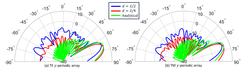
Figure 3 presents the optimized performance for bistatic SCS for the 2-D scattering width in dBm (dB over meter) for -periodic arrays in the -plane. The blue lines represent the scattering patterns for the half-wave spaced arrays. The incident power is rerouted to the desired +70° direction using a 20-element finite-sized patch array along the -dimension. For an infinite periodic reflector, a 0°-to-70° deflection requires a supercell period of , which is not equal to any integer multiple of the unit cell -dimension for these finite arrays.
For the -periodic arrays, the structure designed for TE polarization (Fig. 3(a)) gives a dB side lobe level (SLL) for the highest unwanted side-scattering direction compared to the desired scattering direction. Finally, an SLL of dB is achieved for TM polarized fields, as shown in Fig. 3(b). Although the goal is to attain scattering towards a specific desired angle, the scattering peak is not aligned precisely with the intended angle. A beam pointing error of for the -periodic design is observed. This deviation arises from the constraints imposed by the finite number of individual patch-loaded elements and the relatively coarse half-wave patch spacing in the antenna array.
On top of the SLL, a green-colored SCS pattern is plotted for an ideal anomalous reflection characteristic, which represents a 100% efficiency. It is associated with a reflection coefficient with a linear phase gradient and a constant magnitude corresponding to locally power-conserved reflection. Physically, this ideal model is associated with an active-lossy load impedance distribution. Under the physical optics approximation, analytical results for the 2-D SCS are derived following [29]. Then, the anomalous reflection efficiency is evaluated as the aperture efficiency of scattering into the anomalous direction. In other words, it is defined as the ratio of the 2-D SCS of the optimized physical design to the 2-D SCS of the ideal, analytical model. The TE polarized results depicted in Fig. 3(a) demonstrate an efficiency of 56.9%. Similarly, TM polarized results in Fig. 3(b) produce an efficiency of 63.2% compared to the 2-D SCS analytical model.
III-B Optimized Patch Arrays with a Spacing
To provide a fair comparison with the half-wave spaced array, finiteinfinite, -periodic arrays with a periodic cell of size comprising 80 individual patches for both TE and TM polarizations with a spacing are designed, as depicted in Fig. 2(b). We have now 40 independent load reactance variables, since the two loads on each column should have identical values in order to keep the scattering in the -plane. Repeating the same procedure as in the half-wavelength-spaced design, first, we obtain the initial set of purely-reactive load impedances from the conventional reflectarray method (Appendix A), and then an optimization is performed using the analytical expression for 2-D bistatic SCS (9) for -periodic arrays.
The red curves in Fig. 3 depict the results for -spaced -periodic array. In TE polarization, the ratio of the bistatic SCS for the desired lobe to the highest side lobe gives dB, as seen in Fig. 3(a). Likewise, the results for TM polarized fields are presented in Fig. 3(b), showing the highest SLL of dB. The periodicity design performance is much better as compared with the results. This is an expected result, as the array density is doubled in both dimensions compared with the half-wave spaced case, giving a possibility to control the subwavelength current distribution at the reflector array, which is needed to remove the need of active-lossy loads of the array elements. As depicted in Fig. 3(a), the TE polarization reports an efficiency of 92%, while the TM polarized results in Fig. 3(b) exhibit a similar efficiency of 93.8% compared to the 2-D SCS analytical model. The scattering beam peak for the spacing aligned closer with the intended desired angle compared to spacing. Here, we observe that the reflection efficiencies of the optimized arrays do not closely approach 100%. This is because we are requiring minor scattering lobe levels to be low, as described in Section II-B. This is analogous to targeting low SLLs in antenna synthesis. A tradeoff relation between the SLL and the main beamwidth leads to a slightly weaker SCS in the anomalous direction when minor scattering lobes are suppressed. Specifically, the ideal anomalous reflection is associated with a uniform aperture field for the scattered wave, giving a scattering SLL of −10.5 dB. This is higher than the scattering SLL values of the optimized arrays.
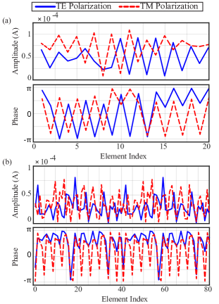
The spacing results show excellent performance for the bistatic SCS with the optimized distribution of reactive loads. The simulated outcomes reveal a dominant scattering lobe while other scattering lobes are suppressed, demonstrating a nearly perfect angle-tunable anomalous deflection. In contrast to the -spaced arrays, a -spaced design offers more degrees of freedom, resulting in better optimization. The induced currents flowing through the patch antenna terminals to anomalously deflect an incident plane wavefront into the desired direction with a fixed and inter-element spacing are presented in Fig. 4, and they shows aperiodic distribution behaviors.
Furthermore, it is noteworthy to discuss the optimization speed to assess the efficiency of the antenna scattering synthesis method. Once the pre-computed data are acquired from the TX antenna simulations, the optimization time increases with an increased number of loaded elements. The time duration for and individual load optimization for and spacing, respectively, is less than a minute to obtain the optimum reactive loads. We utilize an HP EliteBook 845 G7 notebook PC with Windows 10 Enterprise as our hardware platform. Thus, this technique offers scattering maximization in the desired direction by avoiding computationally intensive full-wave EM simulations and prolonged optimization times.
IV Finite Planar Antenna Array
After confirming that the design methodology described in Section II works well for semi-finite arrays, and that a quarter-wave spacing between unit cells is, in terms of scattering performance, superior to a half-wave spacing, we extend the study to finite-size planar arrays, as depicted in Fig. 5 with physical dimensions. With a quarter-wavelength spacing, the array comprises individual loads as free optimization parameters for both TE and TM polarizations. Let us emphasize that we can use the reactive impedances of all the loads as independent optimization variables, as needed when anomalous reflection occurs in a direction off the plane of incidence.
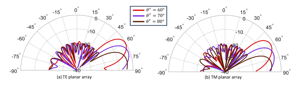
Figure 5 illustrates deflecting the normally incident plane wave into , , and by the finite array designed for TE and TM polarizations. Deflection angles less than 60° are omitted because it is assumed that they can be realized efficiently using the conventional linear phase gradient method. A large deflection of to , , and propagating angles for an infinite periodic reflector requires a supercell period of , , and , respectively. These periodicities do not synchronize with the fixed array period, but continuous scanning across all anomalous reflected beams is enabled using single-period planar finite arrays.
Again, we follow the procedure of Section II, determining , and from full-wave EM simulations using CST. Then, the loads are optimized to steer the incident wave into a desired reflection angle, maximizing .
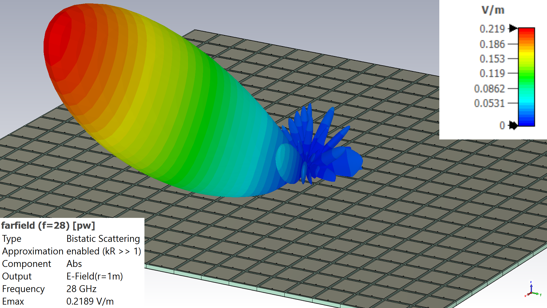
Figure 6 plots the predicted SCS patterns of the optimized planar array with a element spacing. The results have been confirmed by separate full-wave scattering simulations of the optimized designs. The reported outcomes show a dominant scattering beam into the desired direction while minimizing the specular lobe and other undesired reflections. For the TM polarized case, the SLL of the strongest minor scattering beam compared with the field at the desired direction reports dB, dB, and dB for the deflection angles , , and , respectively. Likewise, the designs for TE polarized fields have SLLs of dB, dB, and dB for the respective reflection angles, which are similar to the SLLs of the TM results. The achievable optimized scattering cross-section inevitably decays when the deflection angle approaches 90°, as the projected area of the scattering surface seen in that direction diminishes. Figure 7 demonstrates the 3-D magnitude plot of the scattered -field of the anomalous reflector design for the TM polarization, deflecting a normally incident plane wave into with minimization of all undesired side lobes. In addition to the narrow half-power beamwidth of 19.2° in the -plane owing to collimation via anomalous reflection, the beamwidth in the -plane is narrow at 9.2°.
The optimization for individual load variables takes approximately hours to attain the optimal load impedances.
V Experimental Results
To further validate the performance of the optimized reflectarrays for various deflection angles, we design, fabricate, and characterize a compact finite -GHz anomalous reflector. From the -periodic array design analysis in Section III, a spacing is chosen. The available in-house PCB manufacturing facility and anechoic room test setup are taken into consideration in design to enable practical comparison of the CST simulation results with the experimental scattering pattern. A dual-layer printed circuit board (PCB) is selected for manufacturing using an LPKF Proto laser and galvanic through-hole plating. For measurements, an EM shielded anechoic room with dimensions m is used.
V-A Practical Design and Manufacturing
A finite planar array prototype is designed to be illuminated by a TM-polarized plane wave at normal incidence to have scattering steered to a fixed +70° anomalous reflection angle at 28 GHz. The designed array has metal patches arranged periodically with a period in a square array, resulting in overall dimensions.
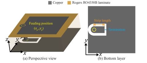
The unit cell is a copper square patch on a PCB, using a Rogers RO4350B laminate with LoPro copper layers (, , a -mm thickness). For simulations, we use the lossy materials definitions available on CST’s material library, assuming annealed copper with a 0.035-mm thickness and surface roughness of 0.001 mm. The square patch length is 2.039 mm, and the feeding position mm is optimized for resonance with a input impedance at the desired frequency. This is a practical choice, suitable for implementing a set of desired load impedances with shorted and open coplanar waveguide (CPW) strips.
Considering further practical implementations, using a wide range of continuously tunable load values might become infeasible. Consequently, the number of possible load values is limited to a 3-bit (a 45° increment) quantization resolution to have distinct phase responses of homogeneous arrays. This discretization of the corresponding load reactances will provide an insight into the robustness of the design method, showing whether inaccurate load impedance values can still provide good anomalous reflection. Additionally, optimization of the load impedances converges significantly faster with a limited number of available load reactance values.
We start our analysis with a -periodic array incorporating 80 individual patch elements. The scattering behavior of a -periodic semi-finite array should be consistent with a large finite rectangular array. The reactive loads are optimized following Section II. Then, we form a panel with elements as a set of optimized linear arrays, to avoid a large preliminary set of simulations with elements. As a final design step, a mapping of the 3-bit load reactances into a practical, equivalent set of shorted and open CPW lines is made, as reported in Table II. The geometry of the proposed single patch antenna, featuring a terminated CPW strip, is illustrated in Fig. 8.
V-B Measurements
| No. | Phase | Reactance | Strip (mm) | Termination |
|---|---|---|---|---|
| 0 | short | |||
| short | ||||
| short | ||||
| open | ||||
| open | ||||
| open | ||||
| open | ||||
| short |
The manufactured anomalous reflector sample is tested in an anechoic chamber organized to carry out bistatic SCS measurements with the device under test (DUT) mounted on a stationary tripod. The physical size of the manufactured PCB panel is approximately mm (-axis) by mm (-axis), and a photograph along with an illustration of the experimental setup is shown in Fig. 9. Standard gain horn antennas with a dBi gain at 28 GHz are used as TX and RX antennas. At a 3 m distance from the DUT, the TX horn antenna connected to a signal generator (SG) is mounted on a fixed pole. The RX horn antenna is at a 2 m distance from the DUT, with a portable spectrum analyzer (SA) as a detector.
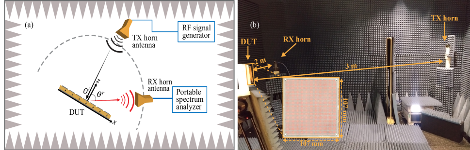
Although a proper far-field condition (the Fraunhofer distance 2.14 m) cannot be satisfied in the test setup, a decent estimate of the scattering pattern is obtained. In the current experimental setup, measurements are conducted at 28 GHz with the receiver moving at a 2.5° angle resolution across the azimuth over . In order to facilitate measurement also in the specular reflection direction, a 2° downtilt is utilized, so that the height of the TX antenna is set to 140 cm, the height of the DUT to 129.5 cm, and the height of the RX antenna to 122.5 cm. The consequence of this positioning is that the angle of incidence for the DUT is not exactly broadside, but it is . The DUT then should reflect the signal to the designed anomalous azimuth angle at a elevation.
Figure 10 compares the normalized scattered patterns obtained from the measurements and simulations, where a good agreement is observed for the whole angular range. The red curve representing the measured data shows a −10 dB ratio of the bistatic SCS of the highest side lobe to the desired anomalous scattering lobe.

VI Conclusion
A numerically efficient design strategy for planar finite-sized anomalous reflectors capable of scanning the deflection beam to any arbitrary angle without parasitic scattering has been demonstrated. Steering and maximizing the directive scattered beam is cast to a circuit domain-based algebraic optimization, which is numerically efficient compared with the traditional full-wave EM simulation-based techniques. A reflector comprises a loaded array of antenna elements treated as a linear multi-port network. Reactive load impedances for individual antennas are optimized to enhance the main scattering lobe and suppress scattering in other directions. The design approach can also synthesize high-efficiency wide-angle reflections using quantized reactive loads, which may be useful in practical tunable reflectors employing digital phase shifters.
This study was performed using a practical array of printed microstrip patches for two- and three-dimensional models. The fabrication and subsequent experimental validation confirms a large fixed-response wide-angle reflector with an optimized set of quantized reactive load values. The results provide an empirical evidence of effective design of anomalous reflectors realizing nearly perfect reflection into an arbitrary direction in a fixed-period configuration. Although the proof of concept has been developed and validated for specific antenna structures at a mmWave frequency, the design approach is general and applicable to a wide range of reflectors comprising loaded scattering elements, as the scattered field is formulated in terms of the generic radiation property of the array. In a load optimization for real-time reconfiguration applications, the impact of losses in practical phase shifters can be incorporated into the design method by introducing a resistance value to every load impedance.
Finally, this technique can be used to shape wave reflections in rather general ways, not limited to anomalous reflectors considered here. For example, there is a problem of parasitic specular reflections and other scattering from offset fed reflectarrays, e.g. [19, 31]. Since the developed method is based on a global optimization of array loads, it is possible to define the incident field as the field of a primary horn at an arbitrary offset position and find the optimal loads for specular reflection elimination, while forming a main beam in the desired direction via coherent addition of anomalously reflected waves.
Appendix A Conventional Reflectarray Method
We use the traditional phase-gradient reflectarray design based on the LPA as the initial guess for the load reactance values and also as a reference. Under the periodic boundary conditions, the patch element in the subwavelength unit cell is simulated for the plane-wave reflection coefficient as a function of the load reactance. This way, we build a design curve as a mapping between the reflection phase and the load reactance. Next, the local reflection phase distribution is calculated analytically from the linear phase gradient relation associated with a given set of incidence and reflection angles. For a normally incident plane wave, the reflection phase for -th patch element with the patch center located at for a deflection angle is then given by
| (11) |
Next, we create a finite patch array loaded with the set of reactive load impedances associated with (11) to provide the -linear reflection phase gradient needed for the anomalous deflection angle, read off of the design curve.
References
- [1] M. Di Renzo, A. Zappone, M. Debbah, M.-S. Alouini, C. Yuen, J. de Rosny, and S. Tretyakov, “Smart radio environments empowered by reconfigurable intelligent surfaces: How it works, state of research, and the road ahead,” IEEE J. Sel. Areas Commun., vol. 38, no. 11, pp. 2450–2525, Nov. 2020.
- [2] M. Di Renzo, F. H. Danufane, and S. Tretyakov, “Communication models for reconfigurable intelligent surfaces: From surface electromagnetics to wireless networks optimization,” Proc. IEEE, vol. 110, no. 9, pp. 1164–1209, Sep. 2022.
- [3] A. Díaz-Rubio, S. Kosulnikov, and S. A. Tretyakov, “On the integration of reconfigurable intelligent surfaces in real-world environments: A convenient approach for estimation reflection and transmission,” IEEE Antennas Propag. Mag., vol. 64, no. 4, pp. 85–95, Aug. 2022.
- [4] A. Díaz-Rubio, V. S. Asadchy, A. Elsakka, and S. A. Tretyakov, “From the generalized reflection law to the realization of perfect anomalous reflectors,” Sci. Adv., vol. 3, no. 8, p. e1602714, Aug. 2017.
- [5] A. M. H. Wong and G. V. Eleftheriades, “Perfect anomalous reflection with a bipartite Huygens’ metasurface,” Phys. Rev. X, vol. 8, Feb. 2018, Art. No. 011036.
- [6] A. Díaz-Rubio and S. A. Tretyakov, “Macroscopic modeling of anomalously reflecting metasurfaces: Angular response and far-field scattering,” IEEE Trans. Antennas Propag., vol. 69, no. 10, pp. 6560–6571, Oct. 2021.
- [7] D.-H. Kwon, “Lossless scalar metasurfaces for anomalous reflection based on efficient surface field optimization,” IEEE Antennas Wireless Propag. Lett., vol. 17, no. 7, pp. 1149–1152, Jul. 2018.
- [8] V. S. Asadchy, M. Albooyeh, S. N. Tcvetkova, A. Díaz-Rubio, Y. Ra’di, and S. Tretyakov, “Perfect control of reflection and refraction using spatially dispersive metasurfaces,” Phys. Rev. B, vol. 94, no. 7, p. 075142, Aug. 2016.
- [9] S. K. R. Vuyyuru, R. Valkonen, D.-H. Kwon, and S. A. Tretyakov, “Efficient anomalous reflector design using array antenna scattering synthesis,” IEEE Antennas Wireless Propag. Lett., vol. 22, no. 7, pp. 1711–1715, Jul. 2023.
- [10] M. Movahediqomi, G. Ptitcyn, and S. Tretyakov, “Comparison between different designs and realizations of anomalous reflectors for extreme deflections,” IEEE Trans. Antennas Propag., vol. 71, no. 10, pp. 8007–8017, Oct. 2023.
- [11] Y. Ra’di and A. Alù, “Metagratings for efficient wavefront manipulation,” IEEE Photon. J., vol. 14, no. 1, pp. 1–13, Feb. 2022.
- [12] A. Casolaro, A. Toscano, A. Alu, and F. Bilotti, “Dynamic beam steering with reconfigurable metagratings,” IEEE Trans. Antennas Propag., vol. 68, no. 3, pp. 1542–1552, Mar. 2020.
- [13] V. Popov, F. Boust, and S. N. Burokur, “Constructing the near field and far field with reactive metagratings: Study on the degrees of freedom,” Phys. Rev. Appl., vol. 11, Feb. 2019, Art. No. 024074.
- [14] V. Popov, M. Yakovleva, F. Boust, J.-L. Pelouard, F. Pardo, and S. N. Burokur, “Designing metagratings via local periodic approximation: From microwaves to infrared,” Phys. Rev. Appl., vol. 11, p. 044054, Apr. 2019.
- [15] X. Wang, A. Díaz-Rubio, and S. A. Tretyakov, “Independent control of multiple channels in metasurface devices,” Phys. Rev. Appl., vol. 14, p. 024089, Aug. 2020.
- [16] V. Popov, F. Boust, and S. N. Burokur, “Beamforming with metagratings at microwave frequencies: Design procedure and experimental demonstration,” IEEE Trans. Antennas Propag., vol. 68, no. 3, pp. 1533–1541, Mar. 2020.
- [17] D. Berry, R. Malech, and W. Kennedy, “The reflectarray antenna,” IEEE Trans. Antennas Propag., vol. 11, no. 6, pp. 645–651, Nov. 1963.
- [18] N. Yu, P. Genevet, M. A. Kats, F. Aieta, J.-P. Tetienne, F. Capasso, and Z. Gaburro, “Light propagation with phase discontinuities: generalized laws of reflection and refraction,” Science, vol. 334, pp. 333–337, Oct. 2011.
- [19] J. Huang and J. A. Encinar, Reflectarray Antennas. Hoboken, NJ, USA: Wiley, 2008.
- [20] P. Nayeri, F. Yang, and A. Z. Elsherbeni, Reflectarray Antennas: Theory, Designs, and Applications. Piscataway, NJ, USA: Wiley-IEEE Press, 2018.
- [21] F. Liu, O. Tsilipakos, A. Pitilakis, A. C. Tasolamprou, M. S. Mirmoosa, N. V. Kantartzis, D.-H. Kwon, J. Georgiou, K. Kossifos, M. A. Antoniades, M. Kafesaki, C. M. Soukoulis, and S. A. Tretyakov, “Intelligent metasurfaces with continuously tunable local surface impedance for multiple reconfigurable functions,” Phys. Rev. Appl., vol. 11, p. 044024, Apr. 2019.
- [22] C. A. Balanis, Antenna Theory: Analysis and Design. Hoboken, NJ, USA: John Wiley & Sons, 2015.
- [23] W. L. Stutzman and G. A. Thiele, Antenna Theory and Design. Hoboken, NJ, USA: John Wiley & Sons, 2012.
- [24] R. Collin, “Limitations of the Thevenin and Norton equivalent circuits for a receiving antenna,” IEEE Antennas Propag. Mag., vol. 45, no. 2, pp. 119–124, Apr. 2003.
- [25] M. T. Tuley, “Antenna RCS and RCSR,” in Radar Cross Section, 2nd ed., E. F. Knott, J. F. Shaeffer, and M. T. Tuley, Eds. Norwood, MA, USA: Artech House, 1993, ch. 10.
- [26] R. C. Hansen, “Relationships between antennas as scatterers and as radiators,” Proc. IEEE, vol. 77, no. 5, pp. 659–662, May 1989.
- [27] R. E. Collin and F. J. Zucker, Antenna Theory. New York: McGraw-Hill, 1969, ch. 4.
- [28] Y. Li, X. Ma, X. Wang, G. Ptitcyn, M. Movahediqomi, and S. A. Tretyakov, “Tunable perfect anomalous reflection using passive aperiodic gratings,” arXiv preprint arXiv:2303.05411, 2023.
- [29] C. A. Balanis, Advanced Engineering Electromagnetics. New York: Wiley, 1989.
- [30] D.-H. Kwon, “Planar metasurface design for wide-angle refraction using interface field optimization,” IEEE Antennas Wireless Propag. Lett., vol. 20, no. 4, pp. 428–432, Apr. 2021.
- [31] J. Budhu and Y. Rahmat-Samii, “Understanding the appearance of specular reflection in offset fed reflectarray antennas,” in 2011 IEEE Int. Symp. Antennas Propag., Aug. 2011, pp. 97–100.