High-Precision Frequency-Controlled Optical Phase Shifter with Acousto Optic Devices
Abstract
A fundamental parameter to determine how electromagnetic waves interfere is their relative phase. Therefore, achieving a fine control over it enables a wide range of interferometric applications. Existing phase control methods rely on modifying the optical path length by either changing the path followed by the light or by altering the thickness or index of refraction of an optical element in the setup. In this work we present a novel method, based on acousto-optic modulators (AOM), which allows adjusting the phase by shifting the frequency of the light in a segment of its path. Since the amount of phase-shift depends on the length of the segment, an optical fiber is used to realize a shift. Two experimental implementations are described which deal with different sources of phase fluctuations. The first addresses fluctuations resulting from the optical fiber while the second also tackles unwanted variations originating from the AOMs.
1 Introduction
Controlling the phase of light is challenging since it usually requires the ability to adjust the optical path length by a small fraction of an optical wavelength, typically in the order of a few nanometers. In spite of these difficulties, achieving control of the phase is of great importance as it finds applications in a large number of fields including holographic [1] and phase-shifting [2] inteferometry as well as homodyne detection in quantum optics [3, 4] and quantum information processing [5] among others.
Several methods can be used for controlling phase shifts, including opto-mechanical, thermo-optical [6] or electro-optical [7]. Another option is to use acousto-optical means [8, 9] where a beam passes through a pair of acousto-optic modulators and the phase difference between the RF signals driving them is used to control the phase of the light. This method effectively displaces the traveling diffraction grating created by the sound waves in the crystal and thus the optical path length is changed.
In this work we propose and demonstrate a novel acousto-optic method for optical phase shifting controlled by the acoustic frequency. As the frequency of the electrical signal, which generates the acoustic wave, can be controlled with a precision of for a common signal generator, this method allows an exceptionally fine tuning of the phase. As opposed to other methods, the method presented in this letter does not rely on modifying the optical path length.
2 Working Principle
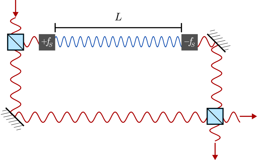
The basic principle of operation of our proposed phase-control method is illustrated in Fig. 1. In the Mach-Zehnder interferometer shown, the phase of one arm is shifted with respect to the other. This is accomplished by, first, shifting its frequency by , then allowing the light to propagate through a distance , and finally shifting the frequency back by before combining both arms in a beam splitter. Since the arm length is fixed the number of wavelengths that fit within changes when varying . In fact, the additional phase acquired due to the frequency shift is , where is the speed of light and the index of refraction of the medium. Therefore, the phase shift range obtained by changing the modulation frequency by an amount is
| (1) |
3 Practical Considerations
To implement the frequency shift we use an acousto-optic modulator (AOM) in a double-pass configuration [10] for which can be tuned by a few tens of without misalignment. This means that to adjust the phase shift in a range of the frequency-shifted path length must be of several meters. However, a compact setup can be obtained by coupling the frequency shifted arm of the interferometer to an optical fiber. Nevertheless, the phase is highly sensitive to variations in the fiber length, which may result from mechanical and thermal changes. The latter also affects the phase due to alterations in the refractive index of the fiber with temperature [11]. The resulting phase fluctuation is
| (2) |
where is the frequency of the light, represents the length fluctuation, and is the refractive index variation.
There is a trade-off involved when choosing . On the one hand, according to Eq. 1 the fiber length can be increased to achieve a larger phase shift range for a given frequency shift , but on the other hand the phase fluctuations increase. In the case of thermal variations, for example, the variation in length of an optical fiber changes proportionally to its total length . Hence, both terms in Eq. 2 increase in proportion to . Therefore, the choice of fiber length should be based on the specific requirements of the application.
Using acousto-optic modulators for frequency shifting introduces an additional effect where the angle of the diffracted light, and consequently the optical path, depends on the frequency. The resulting phase shift, denoted as , due to a change in angle from a frequency change is highly sensitive to the specific position of the optical components so it is challenging to calculate this dependence explicitly. However, despite this sensitivity, the contribution is repeatable because of the one-to-one correspondence between and . Hence, calibrating the phase shifter adequately addresses this effect.
Another factor contributing to phase variation is the phase fluctuation , arising from changes in the width of the AOMs’ crystals due to thermal effects. The thermal origin of this variation poses challenges in achieving precise control over it. Notably, conventional AOM drivers do not exhibit a perfectly flat power output as a function of frequency, leading to fluctuations in the power delivered to the crystal. These fluctuations, in turn, cause unintended changes in the crystal’s width which may lead to systematic errors in the phase shift.
4 Experimental Setup
5 Solución I
The unwanted fiber fluctuations can be reduced by noting that the main contribution presented in Eq. 2 comes from the term with , which is more than six orders of magnitude larger than . Therefore, a straightforward solution to mitigate their effects is to couple both arms of the interferometer into the same fiber and separate them at the output. This results in a strong suppression since, instead of behaving according to Eq. 2, the terms with cancel out and the phase fluctuation due to variations in fiber length or refractive index is given by
| (3) |
Intuitively, if the two arms of the interferometer traverse identical paths, they are subject to the same fluctuations, thus maintaining a constant relative phase difference.
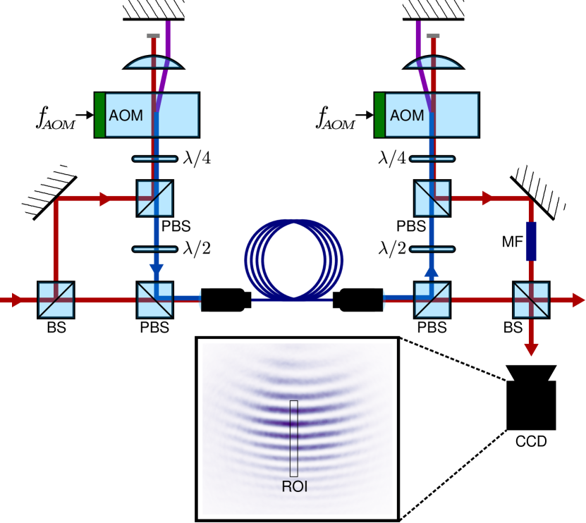
This reasoning motivates the interferometer proposed in Fig. 2, both arms are folded on top of each other with opposite polarization and coupled into a long polarization-maintaining optical fiber. The frequency of one arm is shifted by using an AOM in a double-pass configuration, with the AOM frequency, allowing us to scan while maintaining the fiber coupling. A second AOM in a double-pass configuration subtracts the frequency shift of . Finally, we clean the mode of the frequency-shifted beam with a mode filter (MF) consisting of a single mode fiber before interfering it.
We can estimate the frequency change required to produce phase shift of in this setup. An important difference between the ideal setup of Fig. 1 and the actual experimental setup from Fig. 2 is that as we are using the AOMs in a double-pass configuration the frequency shifted beam travels some distance with an added frequency and other distance with . Measuring all the optical paths to determine we estimate that for a phase shift. However, this calculation only accounts for the phase shift due to the distance propagated with different frequency and to have a quantitative agreement with the measured phase shift also and should be accounted for.
6 Characterization/Proof of concept (solución 1)
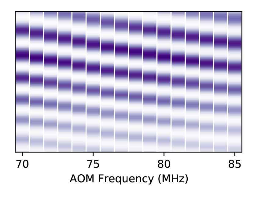
To observe the phase shift we systematically varied the frequency by changing the output frequency of two DDS channels that feed the AOMs while capturing images of the interference pattern. We select a region of interest (ROI) from the captured images and display them as a function of in Fig. 3. During this process, we incrementally adjusted the frequency from to with a interval between each measurement, which was the smallest delay our setup would allow, in order to avoid the effect of slow drifts of the phase.
7 Analysis (solución 1)
Scanning the acoustic frequency results in a displacement of the interference pattern as the phase of one of the arms of the interferometer changes with respect to the other. From this measurement we get that a phase shift requires a frequency shift . However, it is important to note that this required frequency shift may exhibit variations of up to depending on whether it is a one-off measurement or part of a continuous measurement for which a stationary state has been reached. We attribute this effect to the frequency-dependent power delivered by AOM drivers and amplifiers which may cause in transient heating or cooling of the AOMs’ crytals changing the effective optical path introducing a stray phase shift. In particular the high refractive index of the AOM crystal () introduces high variations as it undergoes thermal expansion.
8 Solución II
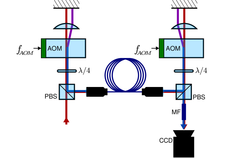
The presented phase shifter can be improved to increase its precision and repeatability by reducing the effect of the AOM crystal thermal fluctuations. We use the same principle of combining both arms of the interferometer into the same path. In the improved case both arms of the interferometer are sent through the AOMs with the non-diffracted beam of the AOM acting as the non-shifted branch of the interferometer while the diffracted beam is used as the shifted branch as shown in Fig. 4. This scenario suppresses the relative optical path fluctuations from and in Eq. 3 and by an analogous argument is also significantly decreased. However, a drawback of this method is that there are additional beams with frequencies and together with the outputs at the original frequency . The net effect of the extra frequencies is that a beat, at frequencies and , appears at the output. Also, now both arms are mixed with the same polarization but they could be separated by using a retarder acting on only one of the orders of the second AOM.
9 Characterization/Proof of concept (solución 2)
Measurements are carried using this modified setup by scanning and recording the output of the interferometer with the camera obtaining the results presented in Fig. 5. Since the interfering beams co-propagate in the same spatial mode there is not a changing fringe pattern as in the previous case and the entire image varies from bright to dark. To maintain the contrast in the oscillating signal we adjust the AOM driver RF power in sync with the frequency to ensure the intensities of the two branches remain in a 50/50 ratio throughout the measurement range. We captured images while increasing the frequency from to . As the AOM efficiency varies with frequency we normalize the measured intensities to remove this effect from the results. To normalize we require an intensity curve as a function of frequency in which the interference effects do not play a role. This is obtained by doing the previously described measurement with a frequency difference of between the two AOMs resulting in an output of the interferometer that blinks at this frequency. As this frequency is much faster than the response time of the camera, only the average intensity is obtained.
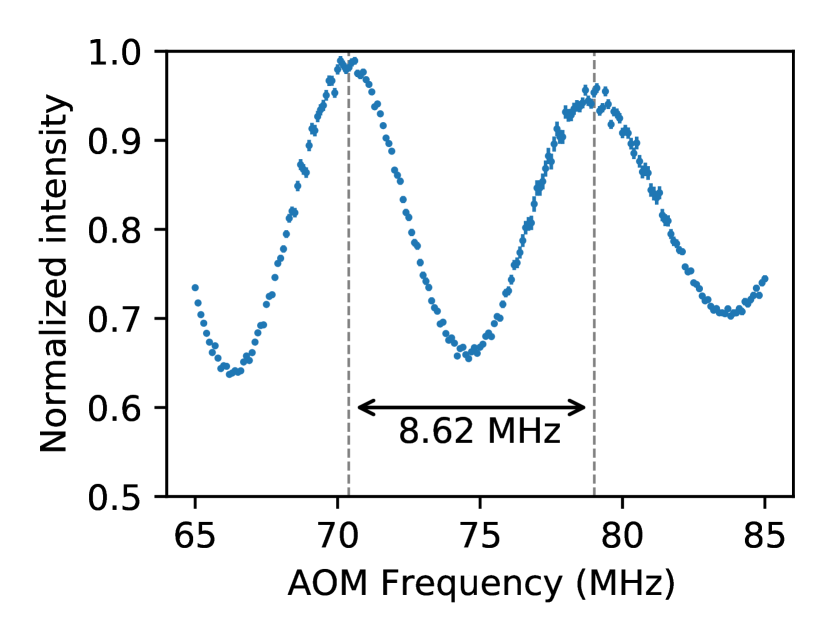
10 Analysis (solución 2)
This optical setup is more robust since most of the relative fluctuations between the interferometer branches are suppressed. For this arrangement we find that is the calibration frequency which corresponds to a phase shift. As the additional beams present oscillate with a frequency of several their intensity at the CCD camera averages which effectively reduces the interference pattern contrast at the output of the Mach-Zehnder interferometer.
11 Conclusions
We introduced and demonstrated a novel method for implementing a high-precision frequency-controlled phase shifter based on acousto-optic modulators. Two experimental setups were developed to address the different experimental fluctuations that affect the performance of the phase shifter. The first one suppresses the phase variations introduced by the optical fiber required for the practical implementation of our phase shifter, and the second one also diminishes the fluctuations due to thermal variations of the AOMs. While the second setup is more reliable, this comes at the expense of having additional frequencies present at the output.
We showed with our setup that a phase shift of can be achieved with a fiber by varying the AOM frequency in a range smaller than . A greater phase shift of several cycles can be achieved by using a longer optical fiber or a greater frequency shift.
In principle, this method offers a typical phase resolution of . However, most experimental implementation would have a passive phase-noise floor much higher that this, so to further exploit this resolution a feedback mechanism [12] could be implemented on the system to stabilize the phase shift in a fixed value using the AOM frequency as a control parameter.
Funding
This work was supported by project UNAM-PAPIIT IN115523, UNAM-CIC LANMAC program and CONACyT Ciencia Básica grant A1-S-29630.
E. E-R., L. U-R., E. G. A-T. and A. H-L. acknowledge fellowships by CONAHCyT.
\bmsectionDisclosures
The authors declare no conflicts of interest.
\bmsectionData availability Data underlying the results presented in this paper are not publicly available at this time but may be obtained from the authors upon reasonable request.
References
- [1] R. L. Powell and K. A. Stetson, \JournalTitleJournal of the Optical Society of America 55, 1593 (1965).
- [2] J. H. Bruning, D. R. Herriott, J. E. Gallagher, et al., \JournalTitleApplied Optics 13, 2693 (1974).
- [3] M. Collett, R. Loudon, and C. Gardiner, \JournalTitleJournal of Modern Optics 34, 881 (1987).
- [4] K. Banaszek, C. Radzewicz, K. Wódkiewicz, and J. S. Krasiński, \JournalTitlePhysical Review A 60, 674 (1999).
- [5] P. Kok, W. J. Munro, K. Nemoto, et al., \JournalTitleReviews of Modern Physics 79, 135 (2007).
- [6] S. Liu, J. Feng, Y. Tian, et al., \JournalTitleFrontiers of Optoelectronics 15, 9 (2022).
- [7] G. Sinatkas, T. Christopoulos, O. Tsilipakos, and E. E. Kriezis, \JournalTitleJournal of Applied Physics 130, 010901 (2021).
- [8] E. Li, J. Yao, D. Yu, et al., \JournalTitleOptics Letters 30, 189 (2005).
- [9] M. J. Ehrlich, L. C. Phillips, and J. W. Wagner, \JournalTitleReview of Scientific Instruments 59, 2390 (1988).
- [10] E. a. Donley, T. P. Heavner, F. Levi, et al., \JournalTitleReview of Scientific Instruments 76, 063112 (2005).
- [11] T. Priest, K. Jones, G. Scelsi, and G. Woolsey, “Thermal Coefficients of Refractive Index and Expansion in Optical Fibre Sensing,” in 12th International Conference on Optical Fiber Sensors, (OSA, Williamsburg, Virginia, 1997), p. OWC41.
- [12] J. Bechhoefer, \JournalTitleReviews of Modern Physics 77, 783 (2005).