Dynamically Reprogrammable Stiffness in Gecko-Inspired Laminated Structures
Abstract
Adaptive structures are of interest for their ability to dynamically modify mechanical properties post fabrication, enabling structural performance that is responsive to environmental uncertainty and changing loading conditions. Dynamic control of stiffness is of particular importance as a fundamental structural property, impacting both static and dynamic structural performance. However, existing technologies necessitate continuous power to maintain multiple stiffness states or couple stiffness modulation to a large geometric reconfiguration. In this work, reversible lamination of stiff materials using Gecko-inspired dry adhesives is leveraged for bending stiffness control. All stiffness states are passively maintained, with electrostatic or magnetic actuation applied for 1s to reprogram stiffness. We demonstrate hinges with up to four passively maintained reprogrammable states decoupled from any shape reconfiguration. Design guidelines are developed for maximizing stiffness modulation. Experimentally, the proposed method achieved a stiffness modulation ratio of up to 14.4, with simulations showing stiffness modulation ratios of at least 73.0. It is anticipated that the stiffness reprogramming method developed in this work will reduce energy requirements and design complexity for adaptation in aerospace and robotics applications.
-
Nov 2023
Keywords: programmable stiffness, adaptive structures, composite materials
1 Introduction
The classic paradigm of structural design yields fixed mechanical properties representing a compromise in performance across various operating conditions. More recently, adaptive structures have focused on dynamically reprogramming mechanical performance of engineering structures [1, 2] – that is, actively changing mechanical response post fabrication. This approach enables structural performance tailored to each operating condition independently. Adaptive structures promise better response to environmental uncertainty and changing loading conditions. Dynamic reprogramming of the stiffness of structural elements is of particular interest due to its impact on a broad range of mechanical performance indices. For example, it can be used to adapt the dynamic response of structures through modification of resonant frequencies [3, 4, 5]. The temporary reduction of stiffness is also advantageous for low-energy shape adaptation in load-carrying structures including morphing wings [6, 2], deployable and adaptive space structures [7, 8], and robotic grippers [9, 10].
Dynamic reprogramming of structural stiffness can be attained through a variety of methods. Material-based approaches leverage temperature-dependent elastic moduli. Shape memory alloys such as NiTi exhibit a temperature- and load-dependent crystal phase transformation with a higher stiffness above their Austenite transition temperature. The different phases show stiffness modulation up to a factor of 4 [11, 12]. Shape memory polymers on the other hand show a drastic reduction of the elastic modulus above their glass transition temperature, allowing stiffness modulation as high as two orders of magnitude [2, 13, 14]. The shape memory effect in these materials is often used for recovering large deformations in adaptive structures [9, 8].
Alternatively, stiffness reprogramming can be attained via phenomena at the structural scale including contact and instabilities. Jamming techniques use meso-scale structural changes by bringing particles or lamina in contact and leveraging friction to increase stiffness. Most commonly this is done by encasing the jammed media in airtight flexible pouches and applying vacuum [15, 16, 17]. Conductive layers separated by thin dielectric films enable laminar jamming via elactrostatic attraction, leading to bending stiffness variation [18, 19, 20]. Lastly, elastic buckling of thin cylindrical shells (i.e., tape springs) or other slender structural elements leads to a large reduction in bending stiffness [21, 7, 22, 23]. Combined with bi-stability, which allows the buckled shape to be maintained without external force, elastic instabilities can reduce energy use in structures with reprogrammable stiffness [24, 25, 26, 27]. While tape springs can induce stiffness changes by factors as high as 400 [7], it is derived from a non-linear moment-curvature relationship and thus stiffness modulation is necessarily coupled to a large shape change.
In addition to the approaches targeted at load-carrying applications, many examples of stiffness reprogramming exist in soft robotics, biomedical, and other disciplines and have been the subject of numerous reviews [28, 29, 1].
Regardless of the technique, a continuous energy input is required to maintain at least one of the stiffness states. For example, continuous heating is necessary to maintain the high stiffness in shape memory alloys or low stiffness state in shape memory polymers, and a persistent external load is needed in jamming methods and elastically buckled structures. The exception to this are bi-stable structures where two shapes with distinct stiffnesses can be held without external force. However, bi-stability shows high sensitivity to boundary conditions [24, 30] and couples stiffness modulation to a large shape change, making it impractical in many applications. As the field has matured, there has also been a growing interest in combining individual reprogrammable stiffness units into large mechanical metamaterials to expand the range of mechanical behavior [27, 5, 31, 32]. Therefore, it is crucial that all operational stiffness states are passive to enable energy-efficient reprogramming and that stiffness is decoupled from shape adaption such that individual units can be readily integrated into engineered metamaterials.
To address this gap, a novel approach is proposed in this work based on reversible lamination of thin load-carrying layers using gecko-inspired dry adhesives. We study dynamic bending stiffness reprogramming in a hinge-like element and demonstrate that two or more stiffness states can be passively maintained for any applied displacement. At the same time, we achieve stiffness modulation on par with existing methods. A combined experimental and finite element approach is presented and performance is explained within a simple analytical framework of a sandwich structure. Section 2 presents the structural and actuation concept for the reprogrammable hinge. The experimental and numerical approaches are introduced in Section 3. Section 4 demonstrates the range of achievable stiffness reprogramming and Section 5 discusses design considerations and compares performance to the state-of-the-art. Lastly, Section 6 concludes the paper.
2 Reprogrammable Stiffness Concept
2.1 Working Principle
We take advantage of gecko-inspired dry adhesives to reversibly laminate load-carrying layers. The proposed hinge-like element with reprogrammable bending stiffness is illustrated schematically in Figure 1(a). The hinge is composed of a functional sandwich structure at its center. Two thin load-carrying layers (‘face-sheets’), with Young’s modulus, , and thickness, , surround a soft dry adhesive core of modulus, , and thickness, . The dry adhesive forms van der Waals bonds with the load-carrying layers when brought into close proximity. This is achieved at the microscale through the high compliance of the dry adhesive material resulting in the formation of van der Waals bonds over a large area [33, 34]. To maintain high absolute stiffness of the hinge, a high modulus material is selected for the load-carrying layers. A permanent stiff adhesive is used at the two ends of the hinge to limit through-thickness shear in bending.
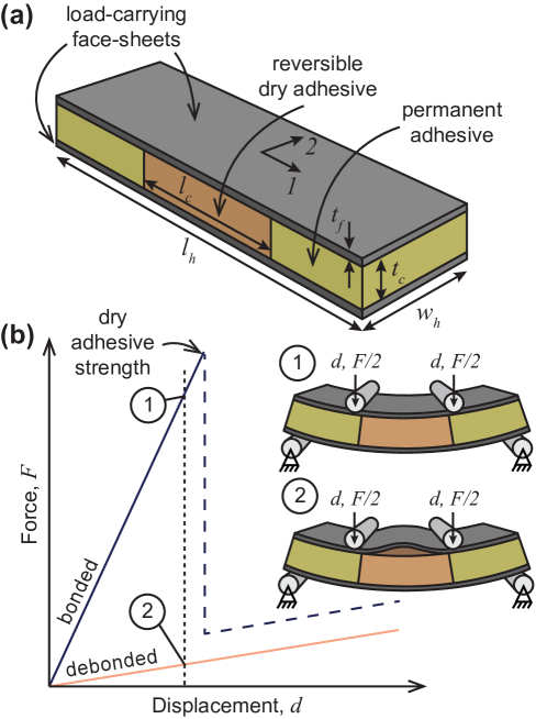
To understand the bending stiffness reprogrammability of the proposed structure, we examine the response of the hinge in four-point bending (Figure 1(b)). When the adhesive is bonded to the two load-carrying layers via van der Waals bonds, the structure bends as a single beam with a high bending stiffness. For sufficiently high displacements, the dry adhesive strength is exceeded and an elastic buckling instability occurs on the compression side, associated with adhesive debonding. Note that for stiffness control purposes, only the initial high stiffness region is of interest. On the other hand, when the dry adhesive is initially debonded, the two load-carrying layers bend upon their individual neutral axis and the bending stiffness is significantly reduced. The face-sheet on the compressive side will elastically buckle due to its small thickness. We refer to these two stiffness states as bonded and debonded, respectively, and note that they can both be passively maintained at any applied displacement (up to the adhesive strength). As such, external energy input is required only to bond and debond the dry adhesive and stiffness reprogramming is decoupled from shape reconfiguration.
The stiffness ratio, , between the bonded and debonded states can be estimated analytically from Classical Lamination Theory (CLT) [35],
| (1) |
where is the longitudinal bending stiffness per unit width of the hinge, following standard CLT notation, is the longitudinal axial stiffness of layer , and are the locations of the layer boundaries from the mid-plane. For the middle section of the hinge where two load-carrying face-sheets are bonded via a dry adhesive core, Equation 1 gives,
| (2) |
where and superscripts refer to the core and face-sheets, respectively, and the bending stiffness contribution of the core layer is neglected since . The debonded bending stiffness can be approximated by adding the bending stiffness of each individual layer,
| (3) |
where the bending stiffness contribution of the core is again negligible. The stiffness ratio is therefore only a function of the thickness of the layers,
| (4) |
This analysis assumes negligible transverse shear deformation in the silicone core (i.e., normals remain normal upon bending). In practice, the stiff permanent adhesive at the ends of the hinge will limit transverse shear deformation in the soft dry adhesive core but will not eliminate it entirely, particularly for high . We also neglect the elastic buckling of the face-sheet on the compression side of the bend in the debonded state. The validity of these assumptions will be investigated in Section 4. Regardless, CLT provides a simple analytic framework to understand the bending stiffness reprogrammability.
Equation 4 shows that for an infinitesimally thin dry adhesive core, this approach yields a stiffness ratio of 4. Increasing the dry adhesive core thickness relative to that of the face-sheets, drastically improves the stiffness variability. For example, for , we expect a maximum stiffness variation by a factor of 28. As will be investigated in Section 4.4, the adhesive and load-carrying layers can be repeated to obtain more than two stiffness states and increase stiffness variation further.
Reversible lamination using dry adhesive yields an effective method of dynamic stiffness reprogrammability where all stiffness states are passively maintained, stiffness modulation and shape adaptation are decoupled, and the stiffness modulation is easily controlled through geometric parameters.
2.2 Actuation Concepts
In this work, we propose two methods for lightweight bonding and debonding of the dry adhesive: electrostatic and magnetic actuation.
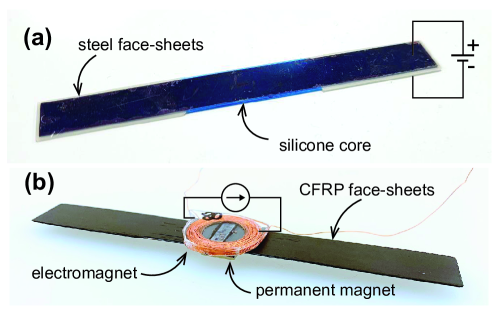
In the electrostatic approach, metallic face-sheets are used as both the load-carrying layers and actuation. Application of a large potential difference () between the two face-sheets creates an electrostatic attractive force between them. This creates a pressure between the dry adhesive and face-sheets and is sufficient to bond the layers. Debonding cannot be achieved using this method and is instead done through external mechanical loading.
In the magnetic approach, non-magnetic face-sheets are used. A small electromagnet realized from a coil of wire is bonded to one face-sheet and a permanent magnet is bonded to the other face-sheet. Application of a current through the coil in one direction attracts the permanent magnet and applies pressure between the dry adhesive and face-sheets, thereby bonding them. Reversal of the current repels the permanent magnet and breaks the van der Waals bonds to debond the layers.
The two methods can theoretically achieve rapid stiffness switching, on the order of the time constant of the actuation circuit () [18]. Embedding of wires in the dry adhesive to heat the layer via resistive heating was also considered. Expansion of the dry adhesive would apply the required pressure for bonding. However, this method has the disadvantage of slow actuation rates and was not pursued.
3 Materials and Methods
3.1 Materials
The electrostatically actuated hinge was fabricated from thin steel sheets (1095 spring steel) for the load carrying layers and thickness-controlled silicone sheets (MoldStarTM 30) for the dry adhesive. An epoxy adhesive (Loctite EA E-20HP) was used to bond the face-sheets at the two ends.
In the magnetically actuated hinge, load-carrying layers were manufactured from HR40 carbon fiber and Thinpreg 513 epoxy prepreg from North Thin Ply Composites with an areal weight of 45 and fiber volume fraction . The dry adhesive was realized from thickness-controlled silicone sheets (Bluesil RTV 3428). To enable actuation, three Neodymium permanent magnets were used in conjuction with an electromagnet coil made from enamel-coated Copper wire with a diameter of 0.22 and 80 turns. The coil was cast in epoxy to better distribute actuation pressures [36].
The material properties of all constituents are summarized in Table 1.
| Hinge Type | Material | [GPa] | [GPa] | [GPa] | [-] | [-] |
|---|---|---|---|---|---|---|
| Electrostatic Actuation | Silicone | 0.00066 | 0.00066 | 0.00022 | 0.49 | - |
| Steel | 206.0 | 206.0 | 147.1 | 0.3 | - | |
| Epoxy | 2.1 | 2.1 | 1.7 | 0.38 | - | |
| Magnetic Actuation | Silicone | 0.0080 | 0.0080 | 0.0078 | 0.49 | - |
| CFRP | 206.2 | 9.1 | 3.4 | 0.26 | 0.55 |
3.2 Hinge Fabrication
A thickness-control process was adopted for the fabrication of all components and hinges in this study. The respective materials were cast in their uncured state between two thick stainless steel plates with a surface roughness of 1.6 and a flatness of 0.03 mm per 100 mm. Precision steel spacers were used between the plates to set the desired thickness.
3.2.1 Dry Adhesive
Dry adhesives typically use micro-scale patterning on their surface with the compliance of these features critical to achieve large contact areas for van der Waals bonds [33]. Bartlett et al. proposed that scalable dry adhesion can instead be attained without patterning by curing silicone on a sufficiently smooth surface and using a fiber reinforcement to increase the shear strength [34]. We follow this strategy in this study. The adhesive strength is dominated by the normal stresses applied to the dry adhesive by the elastic buckling of the face-sheet on the compressive side of the fold. As a result, the fiber-reinforcement of the adhesive is omitted here.
The silicone was cast between the two plates and cured for 24 hours. To facilitate the removal of the dry adhesive after cure, the two plates were staggered and one was lined with a 50 polyimide sheet (Dupont Kapton HN).
3.2.2 Electrostatically Actuated Hinge
The steel layers were cut to size with a paper guillotine. A sharp blade was crucial to ensure that the steel remained flat after cutting. The face-sheets and silicone were stacked on the steel plate and the permanent epoxy adhesive was applied between the face-sheets with a spatula. The hinges were clamped between 10 thick steel plates. Excess epoxy was squeezed out during cure due to the spacers and was trimmed with scissors. A photograph of an electrostatically manufactured hinge is shown in Figure 2(a).
3.2.3 Magnetically Actuated Hinge
The magnetically actuated hinges were made from carbon fiber reinforced polymer (CFRP) prepreg. The prepreg was cut to size and stacked to the desired thickness. For simplicity, unidirectional laminates were used in this study, with the carbon fibers parallel to the hinge length. The load-carrying layers used two layers of prepreg for a total cured thickness of 96 while the number of CFRP layers in the ends was varied to match the silicone adhesive thickness. The prepreg was stacked between two 10 thick steel plates coated with release agent. The spacer thickness was selected to keep the resin bleed between 2 – 10% by weight of the composite. The assembly of prepreg and silicone core was cured in an autoclave using the manufacturer recommended cure cycle (2 hours at 120oC).
Once cured, the actuation was boded to the hinge using adhesive tape (Tesa 05338). The electromagnet was attached at its center using a single 3.5 mm wide strip across the width of the hinge while the permanent magnets used two strips at their ends. This attachment of the actuation was found to best distribute pressure from the actuation and produced the most repeatable results [37]. A photograph of a magnetically actuated hinge is shown in Figure 2(b).
3.2.4 Geometry of Hinge Prototypes
The thickness of all manufactured prototypes is summarized in Table 2. All hinges had a length of with a long silicone core. The width was for both the CFRP and steel hinges. For the steel hinge, silicone adhesive thickness values were measured using a micrometer and the load-carrying layer thicknesses are nominal values according to manufacturer data [38]. For the CFRP hinge, all values were measured using optical microscopy (Keyence VHX-6000). All prototypes had two load-carrying layers with a single adhesive core with the exception of one steel prototype that repeated the layers for a total of three load-carrying and two dry adhesive layers. The latter demonstrated three programmable stiffness states.
| Hinge Type | [] | [] | |
|---|---|---|---|
| CFRP | 3.18 | ||
| Steel | 2.19 | ||
| 3.24 | |||
| 4.32 | |||
| 4.98 | |||
| Steel (3 Layer) | 3.31 |
3.3 Experimental Characterization
The hinge stiffness was characterized using four-point bending (illustrated schematically in Figure 1(b)). For the electrostatically actuated hinges, tests were conducted on an Instron 68TM-50 universal testing machine (UTM) with a 100N load cell. A load span of 45 and a support span of 90 was used. For the magnetically actuated hinges, tests were conducted on a Zwick Roell Z005 AllRoundLine UTM with a 5 kN load cell. A load span of 52 and a support span of 104 was used. In both cases, the hinges were loaded at 5 up to a displacement.
The hinges were actuated directly on the testing machine to minimize the effects of manual handling on the stiffness response. 3D printed PLA bending fixtures were used to minimize interaction with the actuation.
For the electrostatically actuated hinges, a high voltage supply (Stanford Research Systems PS350) was used to apply potential differences up to 1000. For the magnetically actuated hinges, bonding and debonding was done using a DC power supply (RND 320-KA3305P) controlled using the Korad KA3005P software. A prescribed current of 5 was applied to the electromagnet for 1.4 to achieve actuation. In both cases, actuation times had no impact on the stiffness response, and times as low as 1 were sufficient to successfully bond the layers of the hinge.
3.4 Finite Element Simulations
A finite element (FE) model simulating a four point bending test of the hinge was implemented in Abaqus/Standard (Figure 3). The model captures the hinge bending stiffness in the bonded and debonded states and does not attempt to model the adhesive strength. The schematic in Figure 3 shows a hinge with two load-carrying layers and a single dry adhesive layer as in Figure 1 and in the majority of physical prototypes. The FE model can also account for multi-layer hinges with an arbitrary number of dry adhesive layers as will be discussed in Section 4.4.
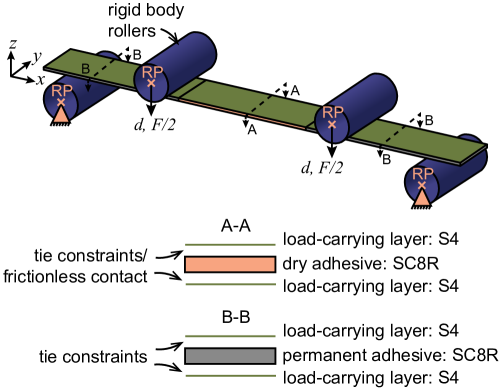
The hinge was modeled as a laminate with two layer types (load-carrying layers and adhesive) with different interaction properties between the layers used to capture the stiffness responses in the bonded and debonded states. The load carrying elements were modeled by their mid-planes using S4 quadratic shell elements with their material properties defined using an orthotropic material to capture all material options in this study. The adhesive layer was modeled using SC8R reduced integration continuum shell elements. This is important to capture the correct response of the relatively thick and soft silicone by allowing the elements to change thickness and accounting for transverse shear deformation [39]. The adhesive layer was partitioned to assign separate material properties to the silicone dry adhesive and permanent adhesive regions. A mesh size of 1 was used for all elements, determined using a mesh convergence study.
Tie constraints were used to simulate permanent bonding between the load-carrying layers at their two ends. To simulate the bonded stiff state, tie constraints were also implemented between the load-carrying layers and the dry adhesive regions. To capture the debonded soft state, frictionless tangential contact and hard normal contact were used between the two instead.
All load-carrying layers that elastically buckle contained a small imperfection to mimic the imperfection-sensitive buckling behavior of thin shells [40]. This was implemented through a 30 amplitude geometric imperfection in the center section of the layer. This method of modeling the imperfection sensitivity was most physical as the manufactured hinges were not perfectly flat.
Bending was applied using four rigid rollers with a 5.0 radius, matching experiments. The motion of each roller was controlled by coupling all of its degrees of freedom to a reference point (RP). The boundary conditions used to apply bending to the hinge are illustrated in Figure 3. Frictional contact with a penalty formulation and a friction coefficient of 0.2 was used to model the tangential interaction between the rollers and the hinge. Hard contact was used for normal behavior.
A geometrically non-linear dynamic implicit analysis was used to solve for the hinge deformation. The quasi-static option was enabled and the loading rate was chosen to limit the kinetic energy at all simulation increments to below 5% of the internal energy. Through this approach, we are able to capture the quasi-static experimental response and circumvent the convergence difficulties of the static solver associated with the elastic buckling instability. An arc-length method can be used instead if the post-buckling response is of interest [41].
4 Results
4.1 Stiffness reprogramming proof of concept
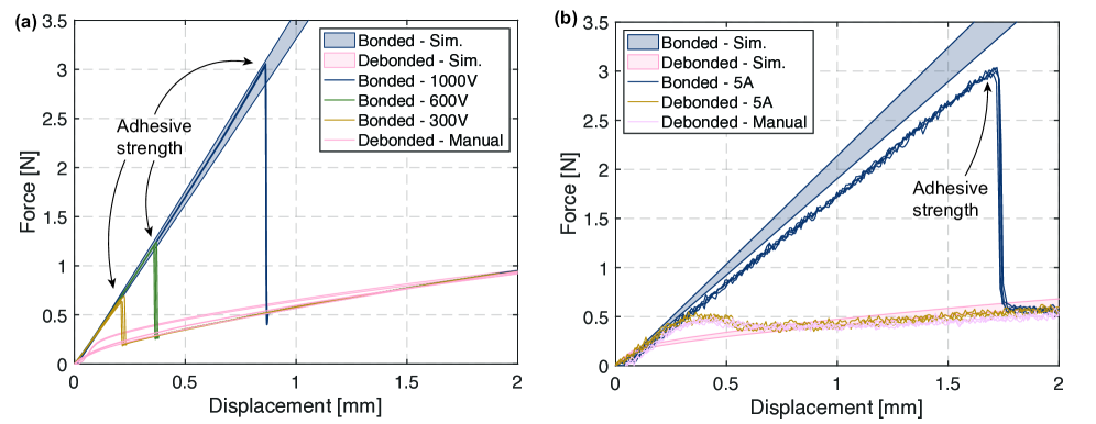
Stiffness modulation is demonstrated for the electrostatically actuated hinge in Figure 4(a). The manually debonded response of the hinge is compared to electrostatic actuation at voltages of 300 V, 600 V and 1000 V. The debonded response shows a small initial region with a higher stiffness before the buckling load of the face-sheet on the compression side is reached. Following this, the desired low stiffness linear regime can be observed. After actuation, we observe a much larger linear stiff response, until the dry adhesive strength is exceeded. The experimentally observed stiffness ratio between the linear portions of the bonded and debonded behaviors is .
Three bonding trials are shown for each actuation voltage, demonstrating excellent repeatability in both bending stiffness (std. dev. = 1.3%) and debonding load (std. dev. = 1.8%). Notably, actuation is only applied for 1s to achieve bonding using the dry adhesive, while both stiffness states can be maintained passively. Higher actuation voltage is beneficial for increasing the adhesive strength, likely due to the formation of Van der Waals bonds over a larger area due to higher electrostatic force. However, it is observed that the adhesive strength is also sensitive to imperfections in the core thickness arising from manufacturing defects. Precise control of clamping forces when curing the epoxy ends is necessary to achieve precise contact between layers without introducing inherent compressive stresses into the core adhesive layer.
The FE predictions for the two operating regimes are shown in the shaded regions in Figure 4(a). The bounds of the regions correspond to the measured standard deviation of the thickness of the dry adhesive layer. The debonded response shows good agreement with the predicted stiffness. The simulations similarly show a small higher stiffness region before elastic buckling, although this region is higher in simulations than measured. A potential explanation is geometric imperfection in the hinge specimen, causing it to buckle more easily. The bonded prediction has excellent agreement with experimental results.
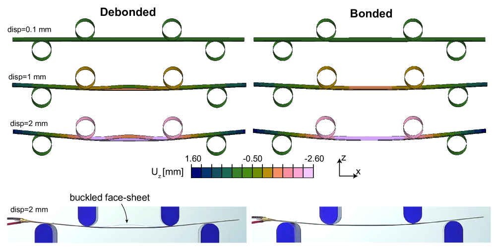
The simulated and experimental deformation of the steel hinge in its debonded and bonded states is illustrated in Figure 5. The buckling of the face-sheet under compression is clearly evident in the debonded case for displacements above . This response is absent in the bonded case.
Stiffness reprogramming is demonstrated in the magnetically actuated hinge as shown in Figure 4(b). In this case, we demonstrate 3 actuation cycles and show that the bonding and debonding actuation is successful at changing the bending stiffness response of the hinge reversibly. Specifically, the debonding actuation yields the same response as a manually debonded hinge. For the magnetically actuated hinge, the measured stiffness ratio is . Simulated behavior agrees well with experimental measurements.
4.2 Control of stiffness modulation using geometry
We test several steel hinges with identical face-sheets but different silicone core thicknesses (as per Table 2). The measured bending stiffness response of these is shown in Figure 6(a) and is in good agreement with FE simulation results. Each sample is tested 3 times in each stiffness state for repeatability, with bonding and debonding done manually. Experimental stiffness values are computed from a 0.3 N pre-load up to a 1.0 cross-head displacement. As expected, the bonded stiffness is easily increased using the core thickness, . The experimental design with the thickest core of achieves a stiffness ratio of .
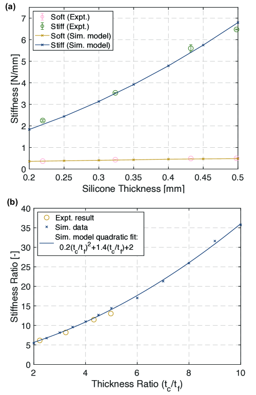
A broader range of core thicknesses in the steel hinges is simulated in Figure 6(b) and is in good agreement with experimental results. A quadratic dependence of the stiffness ratio, , on the thickness ratio is observed. This is as expected from Equation 4. However, the coefficients are much lower than what is predicted analytically leading to lower stiffness modulation. We revisit the model assumptions to understand the discrepancy in the next two sections.
4.3 Comparison of stiffness modulation with analytic prediction
The analytic model in Equation 4 assumes that the rigid ends of the hinge prevent significant shearing of the soft dry adhesive core. As a result, we use CLT without an additional correction factor for transverse shear as is done for thick composites [35]. A transverse shear correction factor of 5/6 is used in the Abaqus finite element software for thick shells and is implemented by default [42].
4.3.1 Deformation of dry adhesive core
We examine the extent of transverse shear in the middle of the hinge through the longitudinal curvature, , of the shells in the bonded state. The most notable aspect is that the curvature is non-uniform in the section between the inner rollers contrary to what would be expected in a four-point bending test that applies pure bending to this section. This is indication of the effects of transverse shear. However, the deviation of the deformation from pure bending has no effect on the overall stiffness of the hinge since . We verify through FE modelling that increasing stiffness of the dry adhesive up to 1% of the stiffness of the load-carrying layers (i.e., dry adhesive with a modulus similar to epoxy) has no impact on the overall stiffness of the hinge. Similarly, modification of the transverse shear stiffness of the dry adhesive from 1 - 1000% that of the computed default has no impact on hinge stiffness. This crucial observation allows us to use a relatively soft material like silicone for its functional properties without sacrificing overall stiffness.
4.3.2 Deformation of the buckled face-sheet
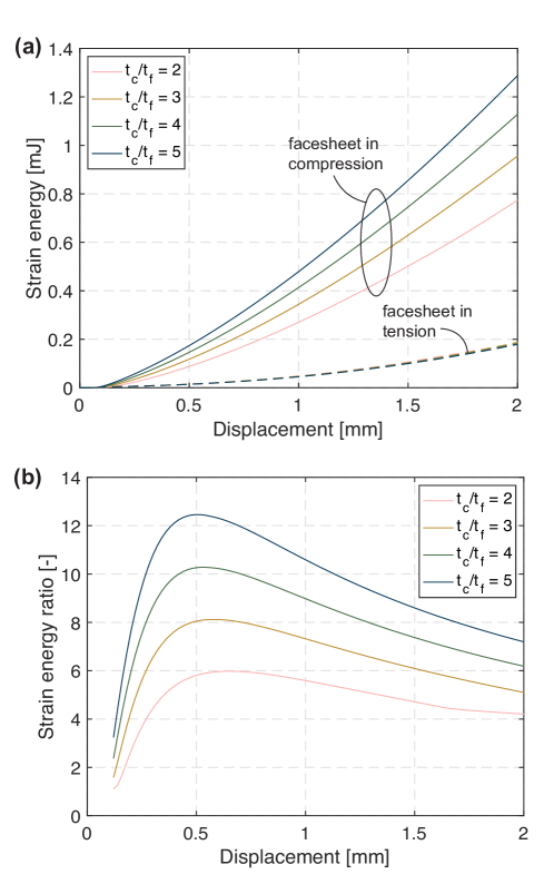
Above, we showed that the soft silicone core does not impact the bonded high stiffness state of the hinge. We now examine the debonded soft stiffness state in more detail to understand the obtained stiffness ratios. Figure 7(a) shows the deformation strain energy in the debonded state for the load-carrying layers on the tensile and compressive sides of the bend for several thickness ratios. It is observed that in all cases the elastically buckled face-sheet on the compression side deforms to higher curvatures and therefore stores higher strain energy. The deformation of the face-sheet on the tensile side is independent of the hinge geometry (i.e., thickness ratio) as it bends upon its own neutral axis. The energy stored in the elastically buckled face-sheet increases with the thickness ratio. The further away this face-sheet is from the mid-plane of the hinge, the larger the compressive buckling force that is applied to it. In fact, this face-sheet stores as much as 12 times the strain energy of the face-sheet on the tensile side as can be seen in Figure 7(b). Therefore, the elastic buckling of the face-sheet in the debonded states must be accounted for when predicting the stiffness ratio as it significantly increases the stiffness of the soft debonded state.
4.4 Expanding the stiffness modulation behavior
We propose the expansion of the stiffness reprogrammability in the laminated hinges by repeating the dry adhesive and load-carrying layers. Figure 8(a) and Figure 9(a) show respectively the behavior of hinges with three and four load-carrying layers, each with . In both cases, we demonstrate that there are as many distinct stiffness layers as load-carrying layers in the hinges. Starting from all interfaces between the stiff layers and the dry adhesive layers being in the bonded state, we can debond the dry adhesive layers one at a time to achieve successively softer stiffness regimes. As long as the load-carrying layers are debonded sequentially starting from the compressive side of the bend, cooperative buckling between the debonded stiff layers is possible. This is shown in the simulated displacement contours in Figure 8(c) and experimentally in Figure 8(d) for a hinge with three load-carrying layers. Visually, there is good agreement between simulated and experimental deformation of the dry adhesive and load-carrying layers. Notably, all stiffness states exhibit a linear response with the exception of small displacements () where the buckling of the stiff layers occurs. The simulated bending response for the three layer hinge is experimentally verified and results are shown in Figure 8(a), with stiffest-to-softest ratio of 14.4 and a intermediate-to-softest ratio of 5.2. For the four layer hinge, we note that a larger geometric imperfection of 60 in simulation is required to achieve buckling in the softest state. The effect on bending stiffness of the increased imperfection is found to be negligible.
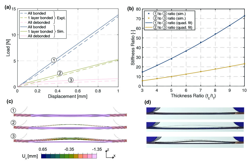
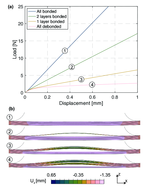
Figure 8(b) shows the achievable stiffness ratios as a function of the thickness ratio for the three layer hinge. The stiffness ratios are always taken relative to the softest, fully debonded state. For example, the blue line shows the stiffness ratio of state 1 relative to 3 and the yellow line shows the stiffness ratio of state 2 relative to 3.
5 Discussion
5.1 Strategy for hinge design
The optimal design strategy for the proposed reconfigurable hinges depends on the design objective. For a fixed total thickness, the stiffness variability is maximized by the design with two load-carrying layers. For example, consider a hinge with a total thickness of with load-carrying layers. The simulated stiffness ratio, , for the two and three layer designs is 21.3 and 14.7 respectively. The elastic buckling of the debonded layers generally reduces the achieved stiffness modulation. On the other hand, the multi-layer hinges are advantageous for achieving more than two stiffness states or if there are limitations on the dry adhesive thickness that can be manufactured. Another consideration is that actuation becomes more difficult for thick dry adhesive layers since electrostatic force scales inversely with the square of the distance between the load-carrying layers [43].
| Technology | Maximum number of stiffness states | Stiffness state maintainability | Shape change and stiffness modulation coupled? | Stiffness modulation ratio, | References |
|---|---|---|---|---|---|
| Shape memory alloys | 2 | Active | No | 2 - 4 | [28, 12, 11] |
| Shape memory polymers | 3 | Active | No | 2 - 100 | [13, 9, 12, 14, 44] |
| Lamina jamming (electrostatic) | 4 | Active | No | 1.2 - 18 | [18, 20] |
| Particle/lamina jamming (pneumatic) | 2 | Active | No | 3 - 50 | [16, 15, 45, 46] |
| Tape springs | 2 | Active | Yes | <400 | [7, 47, 48] |
| Bi-stable tape springs | 2 | Passive | Yes | <100 | [25, 49, 26, 50] |
| Gecko Inspired Laminates | 4 | Passive | No | 6.3 - 14.4 (up to 73 in simulation) | This Work |
5.2 Comparison to existing methods
Table 3 summarizes key performance metrics for stiffness reprogramming methods in literature and this work. The main advantage of the proposed stiffness modulation method is that we can achieve multiple stiffness states and maintain each of them passively – expanding the range of mechanical performance and improving energy efficiency. At the same time, the proposed method does not rely on a large geometric shape change to achieve stiffness modulation (unlike tape springs). In the Gecko-inspired hinge, all stiffness states are accessible at small displacements, while the hinge ends can be mounted with static boundary conditions. This allows it to be easily integrated into structures.
In terms of stiffness modulation, our experimental results perform on par with laminar jamming methods, while easily surpassing the performance of shape memory alloys, used commonly for their variable stiffness performance as actuators. Simulations demonstrate that the stiffness modulation can be improved using simple geometric design parameters, placing the stiffness modulation on par with all other existing methods.
6 Conclusion
In this work, we proposed a Gecko-inspired hinge with dynamically reprogrammable stiffness achieved through reversible lamination of thin stiff layers using dry adhesives via electrostatic or magnetic stimuli. Reprogrammable hinges with up to four distinct stiffness states were studied. All stiffness states are maintained passively due to switchable bonding between load-carrying and dry adhesive layers. Actuation times on the order of 1s were found to be sufficient to activate bonding. The degree of stiffness modulation can be controlled through geometric parameters, with a quadratic proportionality to the ratio of adhesive to load-carrying layer thickness demonstrated. Experimental stiffness responses were found to be repeatable and could be accurately captured by FE simulations. Stiffness reprogramming by a factor of up to 14.4 was shown experimentally, with factors up to 73.0 promised by FE simulations. Hinges with two programmable stiffness states were demonstrated to have the largest stiffness modulation for a given total thickness.
The novel concept addressed two key limitations of existing stiffness control approaches. Namely, all available stiffness states can be passively maintained with energy required only to switch between states and the stiffness reprogramming is independent of shape reconfiguration. The Gecko-inspired hinge reduces energy requirements in adaptive systems and has a broad range of applicability to stiffness modulation in both static (e.g., shape reconfiguration) and dynamic applications (e.g., control of vibration response). As such, the proposed concept is of utility in energy-constrained environments of space, remote robotic exploration, and biomedical devices.
A promising avenue for future work is modeling and predicting the adhesive strength. Improvement of the strength using micro-patterning of the dry adhesive or through modification of adhesive material would enable higher load-carrying capacity in the stiff state. Additionally, the development of extension dominated structures would broaden the applicability of the proposed concept. In this work, stiffness reprogramming is enabled in bending which is ideal for applications like deployable space structures, often packaged using bending of thin composites. Dry adhesion between load-carrying elements can also be applied to structures loaded in tension. In this case, turning adhesion on and off would allow surfaces to transmit loads or slide relative to each other, respectively.
Data Availability
All raw data required to reproduce the findings of this paper is available at: https://doi.org/10.25740/zj277df0909.
Acknowledgments
This research was supported by startup funding from the School of Engineering at Stanford University. Kai Jun Chen was supported by a postgraduate fellowship from DSO National Laboratories - Singapore.
Author Contributions
Kai Jun Chen - Experiment and simulations for electrostatic hinge, literature review, analysis, paper writing and editing. Maria Sakovsky - Idea conception, literature review, experiment and simulations for magnetic hinge, paper writing and editing.
References
- [1] Xiaoxing Xia, Christopher M. Spadaccini and Julia R. Greer “Responsive materials architected in space and time” In Nature Reviews Materials 7.9, 2022, pp. 683–701 DOI: 10.1038/s41578-022-00450-z
- [2] Izabela K. Kuder, Andres F. Arrieta, Wolfram E. Raither and Paolo Ermanni “Variable stiffness material and structural concepts for morphing applications” In Progress in Aerospace Sciences 63 Elsevier, 2013, pp. 33–55 DOI: 10.1016/j.paerosci.2013.07.001
- [3] Henri P. Gavin and Nitin S. Doke “Resonance suppression through variable stiffness and samping mechanisms” In 1999 Symposium on Smart Structures and Materials 3671, 1999, pp. 43–53 DOI: 10.1117/12.348688
- [4] H. X. Deng and X. L. Gong “Adaptive tuned vibration absorber based on magnetorheological elastomer” In Journal of Intelligent Material Systems and Structures 18.12, 2007, pp. 1205–1210 DOI: 10.1177/1045389X07083128
- [5] Hongcheng Tao, Francesco Danzi, Christian E Silva and James M Gibert “Heterogeneous digital stiffness programming” In Extreme Mechanics Letters 55 Elsevier Ltd, 2022, pp. 101832 DOI: 10.1016/j.eml.2022.101832
- [6] Silvestro Barbarino et al. “A review of morphing aircraft” In Journal of Intelligent Material Systems and Structures 22.9, 2011, pp. 823–877 DOI: 10.1177/1045389X11414084
- [7] Sergio Pellegrino “Folding and Deployment of Thin Shell Structures” In Extremely Deformable Structures Springer, 2015, pp. 179–267 DOI: 10.1007/978-3-7091-1877-1˙5
- [8] Oleg Testoni et al. “A 4D printed active compliant hinge for potential space applications using shape memory alloys and polymers” In Smart Materials and Structures 30, 2021, pp. 085004 DOI: 10.1088/1361-665X/ac01fa
- [9] Amir Firouzeh and Jamie Paik “Grasp Mode and Compliance Control of an Underactuated Origami Gripper Using Adjustable Stiffness Joints” In IEEE/ASME Transactions on Mechatronics 22.5, 2017, pp. 2165–2173 DOI: 10.1109/TMECH.2017.2732827
- [10] Christopher Joseph Stabile et al. “The Role of Stiffness in Versatile Robotic Grasping” In IEEE Robotics and Automation Letters 7.2 IEEE, 2022, pp. 4733–4740 DOI: 10.1109/LRA.2022.3149036
- [11] W.B. Cross, A. H. Kariotis and F. J. Stimler “Nitinol Characrerization Study” In NASA Contractor Report, 1969
- [12] Jaronie Mohd Jani, Martin Leary, Aleksandar Subic and Mark A. Gibson “A review of shape memory alloy research, applications and opportunities” In Materials and Design 56 Elsevier Ltd, 2014, pp. 1078–1113 DOI: 10.1016/j.matdes.2013.11.084
- [13] Marc Behl and Andreas Lendlein “Shape-memory polymers” In Materials Today 10.4 Elsevier Ltd, 2007, pp. 20–28 DOI: 10.1016/S1369-7021(07)70047-0
- [14] Geoffrey McKnight et al. “Segmented reinforcement variable stiffness materials for reconfigurable surfaces” In Journal of Intelligent Material Systems and Structures 21.17, 2010, pp. 1783–1793 DOI: 10.1177/1045389X10386399
- [15] Yashraj S. Narang, Joost J. Vlassak and Robert D. Howe “Mechanically Versatile Soft Machines through Laminar Jamming” In Advanced Functional Materials 28.17, 2018, pp. 1–9 DOI: 10.1002/adfm.201707136
- [16] E. Steltz et al. “JSEL: Jamming skin enabled locomotion” In 2009 IEEE/RSJ International Conference on Intelligent Robots and Systems, IROS 2009, 2009, pp. 5672–5677 DOI: 10.1109/IROS.2009.5354790
- [17] Yifan Wang et al. “Structured fabrics with tunable mechanical properties” In Nature 596.7871 Springer US, 2021, pp. 238–243 DOI: 10.1038/s41586-021-03698-7
- [18] Tao Wang et al. “Electrostatic Layer Jamming Variable Stiffness for Soft Robotics” In IEEE/ASME Transactions on Mechatronics 24.2 IEEE, 2019, pp. 424–433
- [19] A. Bergamini, R. X. Christen, B. Maag and M. Motavalli “A sandwich beam with electrostatically tunable bending stiffness” In Smart Materials and Structures 15.3, 2006, pp. 678–686 DOI: 10.1088/0964-1726/15/3/002
- [20] Luigi Di Lillo et al. “Tuning the mechanical behaviour of structural elements by electric fields” In Applied Physics Letters 102.22, 2013, pp. 224106 DOI: 10.1063/1.4809728
- [21] F. P. J. Rimrott “Storable Tubular Extendible Member: a unique machine element” In Journal of Machine Design 37, 1965, pp. 156–165
- [22] Sicong Shan et al. “Multistable Architected Materials for Trapping Elastic Strain Energy” In Advanced Materials 27.29, 2015, pp. 4296–4301 DOI: 10.1002/adma.201501708
- [23] Tian Chen and Kristina Shea “An Autonomous Programmable Actuator and Shape Reconfigurable Structures using Bistability and Shape Memory Polymers” In 3D Printing and Additive Manufacturing 5.2, 2018, pp. 90–101 DOI: 10.1089/3dp.2017.0118
- [24] Andres F Arrieta, Izabela K Kuder, Tobias Waeber and Paolo Ermanni “Variable stiffness characteristics of embeddable multi-stable composites” In Composites Science and Technology 97 Elsevier Ltd, 2014, pp. 12–18 DOI: 10.1016/j.compscitech.2014.03.017
- [25] Cezar G. Diaconu, Paul M. Weaver and Filippo Mattioni “Concepts for morphing airfoil sections using bi-stable laminated composite structures” In Thin-Walled Structures 46.6, 2007, pp. 689–701 DOI: 10.1016/j.tws.2007.11.002
- [26] Sungeun Jeon and Thomas Murphey “Design and analysis of a meter-class CubeSat boom with a motor-less deployment by bi-stable tape springs” In 52nd AIAA/ASME/ASCE/AHS/ASC Structures, Structural Dynamics and Materials Conference, 2011, pp. AIAA 2011–1731 DOI: 10.2514/6.2011-1731
- [27] Tian Chen, Mark Pauly and Pedro M. Reis “A reprogrammable mechanical metamaterial with stable memory” In Nature 589.7842 Springer US, 2021, pp. 386–390 DOI: 10.1038/s41586-020-03123-5
- [28] Mariangela Manti, Vito Cacucciolo and Matteo Cianchetti “Stiffening in soft robotics: A review of the state of the art” In IEEE Robotics and Automation Magazine 23.3 IEEE, 2016, pp. 93–106 DOI: 10.1109/MRA.2016.2582718
- [29] Erick I. Saavedra Flores, Michael I. Friswell and Yuying Xia “Variable stiffness biological and bio-inspired materials” In Journal of Intelligent Material Systems and Structures 24.5, 2013, pp. 529–540 DOI: 10.1177/1045389X12461722
- [30] Yuefeng Cui and Matthew Santer “Highly multistable composite surfaces” In Composite Structures 124 Elsevier Ltd, 2015, pp. 44–54 DOI: 10.1016/j.compstruct.2014.12.052
- [31] Babak Haghpanah et al. “Programmable Elastic Metamaterials” In Advanced Engineering Materials 18.4, 2016, pp. 643–649 DOI: 10.1002/adem.201500295
- [32] Ryan H. Lee, Erwin A.B. Mulder and Jonathan B. Hopkins “Mechanical neural networks: Architected materials that learn behaviors” In Science Robotics 7.71, 2022, pp. 1–10 DOI: 10.1126/scirobotics.abq7278
- [33] Wei Wang, Yang Liu and Zongwu Xie “Gecko-Like Dry Adhesive Surfaces and Their Applications: A Review” In Journal of Bionic Engineering Springer Singapore, 2021 DOI: 10.1007/s42235-021-00088-7
- [34] Michael D. Bartlett et al. “Looking beyond fibrillar features to scale gecko-like adhesion” In Advanced Materials 24.8, 2012, pp. 1078–1083 DOI: 10.1002/adma.201104191
- [35] I. M. Daniel and O. Ishai “Engineering mechanics of composite materials” Oxford: Oxford University Press, 2006 DOI: 10.1016/s0261-3069(97)87195-6
- [36] Cyrill Schmid and Maria Sakovsky “Variable Stiffness Structures through Reversible Lamination Using Dry Adhesives” In AIAA SCITECH 2022 Forum, 2022, pp. 0652
- [37] Cyrill Schmid and Maria Sakovsky “Variable stiffness hinges through reversible lamination using dry adhesives” In AIAA SciTech 2022 Forum, 2022, pp. AIAA 2022–0652 DOI: 10.2514/6.2022-0652
- [38] In McMaster URL: https://www.mcmaster.com/9014K11/
- [39] Simulia “ABAQUS Analysis User’s Manual - Choosing a shell element”, 2021
- [40] Don O. Brush and Bo O. Almroth “Buckling of Bars, Plates, and Shells” McGraw-Hill, 1975
- [41] E. Riks “An incremental approach to the solution of snapping and buckling problems” In International Journal of Solids and Structures 15.7 Pergamon Press Ltd., 1979, pp. 529–551 DOI: 10.1016/0020-7683(79)90081-7
- [42] I Abaqus “Abaqus documentation” In Version 6, 2014, pp. 1–5
- [43] A. Bergamini, R. Christen and M. Motavalli “Electrostatically tunable bending stiffness in a GFRP-CFRP composite beam” In Smart Materials and Structures 16.3, 2007, pp. 575–582 DOI: 10.1088/0964-1726/16/3/004
- [44] Thomas P. Chenal, Jennifer C. Case, Jamie Paik and Rebecca K. Kramer “Variable stiffness fabrics with embedded shape memory materials for wearable applications” In IEEE International Conference on Intelligent Robots and Systems IEEE, 2014, pp. 2827–2831 DOI: 10.1109/IROS.2014.6942950
- [45] Allen Jiang et al. “Robotic Granular Jamming: Does the Membrane Matter?” In Soft Robotics 1.3, 2014, pp. 192–201 DOI: 10.1089/soro.2014.0002
- [46] Vincent Wall, Raphael Deimel and Oliver Brock “Selective stiffening of soft actuators based on jamming” In Proceedings - IEEE International Conference on Robotics and Automation 2015-June.June IEEE, 2015, pp. 252–257 DOI: 10.1109/ICRA.2015.7139008
- [47] Sang Min Baek et al. “Ladybird beetle-inspired compliant origami” In Science Robotics 5.41, 2020, pp. eaaz6262 DOI: 10.1126/SCIROBOTICS.AAZ6262
- [48] Matthew Santer and Andrew Whealey “Composite Tube Flexures at Nanosatellite Scale” In 4th AIAA Spacecraft Structures Conference, 2017, pp. AIAA 2017–0622 DOI: 10.2514/6.2017-0622
- [49] Andres F. Arrieta et al. “Passive load alleviation aerofoil concept with variable stiffness multi-stable composites” In Composite Structures 116.1 Elsevier Ltd, 2014, pp. 235–242 DOI: 10.1016/j.compstruct.2014.05.016
- [50] Joseph Costantine et al. “Cubesat deployable antenna using bistable composite tape-springs” In IEEE Antennas and Wireless Propagation Letters 11, 2012, pp. 285–288 DOI: 10.1109/LAWP.2012.2189544