Quantum-secured single-pixel imaging under general spoofing attacks
Abstract
In this paper, we introduce a quantum-secured single-pixel imaging (QS-SPI) technique designed to withstand spoofing attacks, wherein adversaries attempt to deceive imaging systems with fake signals. Unlike previous quantum-secured protocols that impose a threshold error rate limiting their operation, even with the existence of true signals, our approach not only identifies spoofing attacks but also facilitates the reconstruction of a true image. Our method involves the analysis of a specific mode correlation of a photon-pair, which is independent of the mode used for image construction, to check security. Through this analysis, we can identify both the targeted image region by the attack and the type of spoofing attack, enabling reconstruction of the true image. A proof-of-principle demonstration employing polarization-correlation of a photon-pair is provided, showcasing successful image reconstruction even under the condition of spoofing signals 2000 times stronger than the true signals. We expect our approach to be applied to quantum-secured signal processing such as quantum target detection or ranging.
I Introduction
Quantum security, security based on quantum phenomena, has been studied extensively in the quantum information field. Quantum key distribution (QKD) [1, 2, 3] and blind quantum computation (BQC) [4, 5, 6] are representative quantum information protocols that exploit quantum phenomena based quantum security including the no-cloning theorem [7, 8], uncertainty relation [9, 10], and quantum measurement [11, 12, 13]. In both protocols, by analyzing changes of quantum states, or state errors, one can notice the existence of an adversary. Therefore, quantum security is fulfilled if information encoded in the quantum states is used only when there is no adversary.
In quantum sensing, there have been various studies on the rejection of environmental hindrances, especially external noise [14, 15, 16, 17, 18]. However, only a few studies have been conducted on preventing a spoofing attack, i.e., an attempt to deceive a sensing system by sending falsified signals to the system [19, 20, 21, 22]. A primary quantum-secured imaging (QSI) method was proposed in 2012 [19] which provides threshold-type quantum security for an encoding mode, such as the polarization mode of a photon. Threshold-type quantum security means that there is a threshold error rate, which is an error rate obtained under the assumption of the optimal attack, and a protocol is interrupted when an error rate exceeds the threshold. Thus, in QSI, an obtained image is trusted only when a detected error rate is below the threshold; otherwise, it is discarded even if true information is included.
In QSI, encoding modes for a security check does not directly contribute to image formation, while QKD and BQC exploit encoding modes for both data processing and security analysis. This implies that QSI does not necessarily have the same form of security analysis as the previous quantum-secured protocols. Recently, there was a proposal for quantum-secured single-pixel imaging (QS-SPI) which tries to extract a true image under a certain kind of spoofing attack by an adversary [22]. However, its security analysis considered only the optimal attack, which is an intercept-and-resend attack, so that it also provides threshold-type quantum security. Therefore, under a non-optimal attack, the extracted true image can be distorted.
In this paper, we present a QS-SPI method that can provide a true image under a spoofing attack. Our method exploits a mode-correlation of a photon-pair for security analysis. In our method, a type of spoofing attack is revealed by analyzing an erroneous image area and an error rate. With the detailed information of the attack, if true signals exist in detected signals, our method can reconstruct a true image even if the true signals are buried under strong fake signals. Thus, our method provides a new type of quantum security distinct from threshold-type security. We experimentally demonstrated our method with polarization-correlation of a photon-pair to compare reconstructed images of our method to a true image. We expect that adopting advanced techniques used in the existing quantum-secured protocols can further improve our method.
II Quantum-Secured Single-Pixel Imaging and spoofing attack
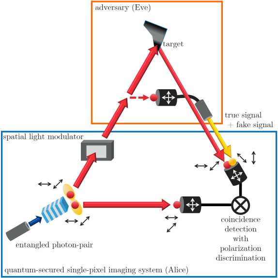
The conceptual framework for QS-SPI is presented in Fig. 1. Initially, an entangled photon-pair is prepared. For illustration, we employ the polarization-correlation of the photon pair. However, alternative degrees-of-freedom may be exploited for QS-SPI. The signal photon of the photon-pair undergoes spatial intensity encoding through a spatial light modulator (SLM) before interaction with a target. After the interaction, measurements are conducted to obtain the polarization and timing information of the received photon. Simultaneously, the idler photon is directly measured to analyze the temporal and polarization correlations between two photons. As a result, spatial information of the target and polarization correct- and mismatched-coincidence rates of the photon pairs is obtained.
In the polarization measurement, one of two mutually unbiased bases (MUBs) is randomly chosen, such as a rectilinear basis and a diagonal basis. The rectilinear basis consists of horizontal and vertical polarization, and the diagonal basis consists of diagonal and anti-diagonal polarization. The polarization states are related with the following equations: and , where denotes a single photon -polarization state, and , , , and denote horizontal, vertical, diagonal, and anti-diagonal polarization, respectively.
In SPI, an image is constructed from the spatial correlation between encoding patterns on SLM and measured coincidence rates, i.e., , where is a spatial correlation, is a pixel position, is the -th encoding pattern, is a coincidence rate, and denotes the average for the whole trials [23, 24].
During the target interaction phase, a user of the imaging system, called Alice, may encounter potential adversarial threats in the form of deceiving images by falsified data: a so-called spoofing attack. To accomplish the attack against SPI, an adversary, called Eve, should control Alice’s coincidence rate according to Alice’s spatial patterns. This can be realized by sending fake signals in diverse strategies such as substituting all/partial signals with fake signals, or illuminating strong patterned-jamming signals without blocking true signals to increase the accidental coincidence rates.
III Security analysis for spoofing attacks
Due to the no-cloning theorem, Eve should interact with Alice’s signal photon to obtain temporal and polarization information which introduces a change of the quantum state. Since we exploit two MUBs, if Eve’s basis is different from Alice’s, polarization of the prepared and received photons can be mismatched [19, 22]. To analyze the images constructed from the true and fake signals, the following spatial correlations are considered:
| (1) | ||||
where the subscriptions and denote true and fake, respectively. , , and are obtained from all, correct, and mismatched polarization coincidence rates, respectively. These three spatial correlations are directly obtained from experimental data while true and fake spatial correlations are not. A fake signal error rate, , is an error rate induced by Eve’s signal only. Since it is determined by Eve’s attack strategy, estimation of is the key to uncovering the attack strategy of an adversary; thus, a reconstructed image gets close to the true image with an exact estimation of . Let us define a polarization state error rate, , which is obtained from (mismatched coincidence rate)/(all coincidence rate). The relation between and becomes . Therefore, is satisfied only when there is no true signal. Note that should be satisfied since 25% is the fake signal error rate induced by the optimal attack: an intercept-and-resend attack [19, 22].
To specify Eve’s attack strategy, we define the following values:
| (2) | ||||
If Eve interacts with all signals, i.e., there is no true signal, should be satisfied where an arithmetic mean of composite pixel values of is written as and denotes an erroneous area. In this case, reconstruction of the true image is impossible. However, does not imply the absence of a true signal. To clarify Eve’s strategy, should be exploited. Only when can we conclude that there are no true signals; otherwise, true image reconstruction is possible (See Appendix A).
Image reconstruction is conducted with which is the estimation of . At the pixel , , if there is no true signal, when true signals exist. The condition guarantees that implies the existence of true signals. Therefore, the estimation becomes more accurate for the region rather than for since the pixels in are closer to . The estimated error rate is obtained from . With and Eq. 1, a reconstructed true image is formed based on the following equation:
| (3) | ||||
where .
Since no specific strategies for sending a fake signal are assumed, our method can be applied to any spoofing attack scenario. The true image reconstruction method is based on a QSI system that performs imaging and security analysis using the same data. If the two are executed with different data, has no relation with the images; thus, neither the attack discrimination nor reconstruction of the true image is possible.
In summary, security analysis for QS-SPI under a general spoofing attack is conducted as follows:
-
1.
Using and , the possibility of true image reconstruction is determined as follows:
-
•
: possible.
-
•
& : possible.
-
•
: impossible.
-
•
-
2.
If the reconstruction is possible, Alice can obtain a credible image by Eq. 3 with .
IV Proof-of-Principle Demonstration
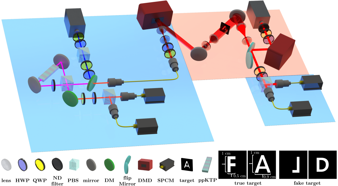
Fig. 2 shows a schematic of the QS-SPI experimental setup. In Alice’s setup, depicted by the blue region in the figure, 810 nm entangled photon pairs were created by pumping a periodically poled potassium titanyl phosphate (ppKTP) crystal using a 405 nm continuous wave (CW) laser. The ppKTP is located inside a Sagnac interferometer setup for generating the polarization entangled Bell state [25], . The fidelity of the generated state was 98.6%. The entangled pairs are detected by single photon counting modules (SPCMs, Excelitas Technologies, SPCM-780-13-FC) with polarization discrimination. The bases are randomly chosen by wave plates, but the bases of the signal and idler are always identical. A digital micromirror device (DMD, Vialux GmbH, DLP650LNIR) was exploited for spatial intensity modulation.
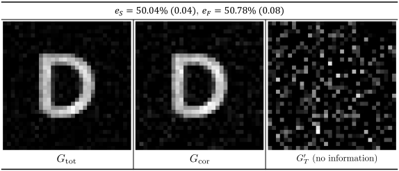
Eve’s setup, shown in red in Fig. 2, is composed of an 810 nm CW laser and another DMD. Eve’s DMD encodes fake target information to fake signals by displaying an overlap of an Alice’s imaging pattern and a fake target image. We demonstrated two targets: a true target “A” having overlap with a fake target “D,” and a true target “F” having no overlap with a fake target. Both are combined to show the form of the digital number “8.”
By controlling the flip mirror, true and fake signals are selectively received. When the flip mirror blocked the true signal and reflected the fake signal, only the fake signal was detected, and if the flip mirror did nothing to the signals, the true signal was detected. Since we do not have an on-demand single-photon generator, an attack was simulated by blocking a true signal and illuminating strong light for accidental coincidence. Eve’s attack was simulated by mixing the two data. The detections were analyzed by coincidence counts in each polarization combination. Two attack strategies are demonstrated: a patterned-jamming attack with random polarization and an intercept-and-resend attack. The details of the demonstration are given in Appendix B.

Fig. 3 shows the obtained images under a patterned-jamming attack with random polarization when the fake signal is 500 times stronger than the actual signal. A target is the letter “F,” and this attack makes the imaging system construct the digital number “8” by using fake signals. All images shown are normalized to a scale of 0 to 255 pixel values. The theoretical fake signal error rate is for this attack. The polarization state error rate of the obtained image is with a standard deviation of , making it undetectable by the original QSI [19]. The digital number “8” is constructed from both the original SPI () and polarization-filtered SPI (. The previous QS-SPI [22] and our QS-SPI can construct the true image “F”. However, the previous QS-SPI overly deletes the area of . This effect will be described in the following examples. The estimated fake signal error rate is .
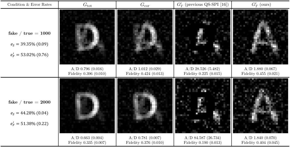
Fig. 4 shows the obtained images under a patterned-jamming attack with random polarization when the true target is the letter “A,” and the fake target is “D.” The fake signal is 1000 and 2000 times stronger than the true signal. Similar to the previous image, the original SPI and SPI with polarization filtering cannot obtain the true image, while our QS-SPI can reconstruct a true image. Since this is not an optimal attack, the previous QS-SPI [22] overly deletes the fake image; thus, the reconstructed image is far from the true image.
To compare the quality of the true image, we exploit two measures: the A to D ratio and fidelity. First, the fidelity is obtained with the true target “A” shown in Fig. 2. Let us define the spatial correlation of the true target as , then for the “A” region and otherwise. The fidelity is calculated from where is an experimentally constructed spatial correlation. A correlation of the fake target can be obtained in the same way. We can then define the A to D ratio as . The A to D ratio quantifies the restoration of the true image and rejection of the fake signal. The fidelity is used to quantify the quality of the true image. Here, we compared the A to D ratio of , , and (ours), and the fidelity of of the previous QS-SPI and ours.
From the A to D ratio, the reconstructed image obtained by our QS-SPI is closer to the true image and farther from the fake image compared to and . The image obtained by the previous QS-SPI has the highest A to D ratio since the pixels in the fake image region are mostly 0 due to over-deletion. The fidelity shows that the image obtained by our QS-SPI is closer to the true image than that by the previous QS-SPI.
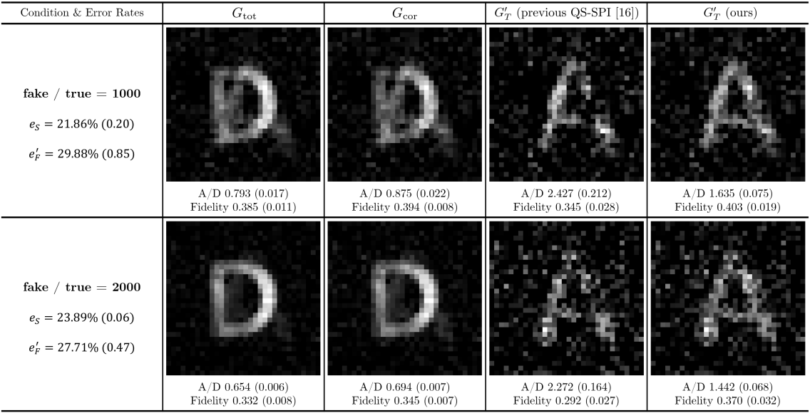
Fig. 5 shows obtained images under an intercept-and-resend attack. Since the state error rate is below , the original QSI cannot detect this attack. Different from the patterned-jamming attack case, the previous QS-SPI [22] well reconstructs the true image. Comparing the qualities of the images obtained by the two QS-SPI protocols, the previous QS-SPI is better than ours in the A to D ratio. However, as shown in Fig. 4, the previous QS-SPI overly deletes the fake image information since the protocol works under the assumption of an ideal intercept-and-resend attack. From our QS-SPI, the estimated fake signal error rates, and , are close to the ideal fake signal error rate of an intercept-and-resend attack: . However, the existence of a small variation means that the intercept-and-resend attack is not perfectly demonstrated for some experimental reasons. Thus, the previous QS-SPI still overly deletes the fake signal information in the demonstration. Therefore, our QS-SPI provides higher fidelity compared to the previous QS-SPI.
Lastly, Fig 6 shows the obtained images under a patterned-jamming attack with random polarization and no true signals. The state error rate is and the fake signal error rate is very similar at . Thus, we can conclude there is no true signal. This is also verified from the image reconstruction ; since there is no true signal, only white noise is shown in the reconstructed image.
V Summary and Discussion
In this paper, QS-SPI under a general spoofing attack is presented. Like QKD, the original QSI [19] and the previous QS-SPI [22] considered only the optimal attack and provided threshold-type quantum security, i.e., if the error rate is higher than the error threshold, the protocol is interrupted even when true signals exist. However, our QS-SPI does not assume a specific attack strategy, and thus, the type of spoofing attack can be discovered by using our method. Moreover, it is possible to reconstruct a true image under various types of spoofing attacks. A proof-of-principle demonstration of our QS-SPI is provided, and we show the reconstructed true images with our QS-SPI have better quality compared to the previous methods.
Similar to the previous QS-SPI [22], we expect that the security of our QS-SPI can be enhanced with the advanced techniques exploited in quantum secure communication, such as protocols based on three mutually unbiased bases [26], high-dimensional quantum states [27, 28, 29, 30], and hyper-entangled states [31, 32]. Although the demonstration of our method is limited to an SPI system in this paper, the methods are expected to be adopted in other applications such as quantum target detection [14, 33] or quantum target ranging [34, 35]. In particular, LiDAR [36, 37, 38, 39, 40] can provide higher security not only against a jamming attack with external noise rejection [15, 16, 17, 18], but also against a spoofing attack with our method.
Acknowledgements.
This work was supported by a grant funded by the Defense Acquisition Program Administration and Agency for Defense Development.Appendices
Appendix A Spoofing attack with true and fake signal mixing
From Eq. 1 and Eq. 2, under a spoofing attack by mixing true and fake signals is
| (4) |
This shows that the presence of lowers pixel values below . Therefore, if , a true signal exists. However, does not guarantee that there is no true signal. For example, if exists in half of and inside and , then , although a true signal exists. Still, the cases are distinguishable by using .
Failure to discriminate the two cases is equivalent to the following: with true signals, if , then . To analyze this statement, let us define the -th area in as where and the composite pixel values are identical to a constant value . Therefore, in that area, . Assume a total of areas exist in where . Lastly, let us define the area where inside as . Since we assume that there is a true signal and , exists in , then, gives
| (5) |
Using Eq. 5, is
| (6) | ||||
| (7) |
, where the last inequality is the Cauchy-Schwarz inequality. For to be accomplished, the last equality should be satisfied. However, equality is reached only when all values are equal to 1, indicating that in . This contradicts the assumption that . Therefore and together can always discriminate the existence of a true signal. If and , then there is a true signal; if , then there is no true signal.
Appendix B Demonstration details
Spatial patterns are crucial for the quality of SPI [41, 42, 43]. For enhancing imaging quality and efficiency of the process, orthogonal pattern sets are used such as Hadamard patterns [44, 45, 46, 47], which are used for our experimental demonstration of QS-SPI.
The Hadamard matrix of order is constructed as
| (8) |
where
| (9) |
and denotes the tensor product. Reshaping each row of a Hadamard matrix of order into a square matrix, a total of Hadamard patterns of resolution are obtained. The patterns include negative elements. To display the pattern set to an SLM with intensity modulation such as a digital-micromirror-device (DMD), two shots are required for a single pattern: a pattern formed by transitioning elements as white and as black, and the opposite [24]. Therefore, a total of shots are required for a resolution image. This can be reduced to half by one-shot detection of a single pattern through various techniques [48].
We used Hadamard patterns reconstructed based on a Hadamard matrix of order . Therefore, 2048 shots are required for construction of an image. The resolution of the images is .
To simulate a spoofing attack, fake signals are illuminated to the detection system for an accidental coincidence. Due to the loss of true signals in the target interaction, fake signals can induce accidental coincidence. By controlling the power of the illumination, Eve can manipulate Alice’s coincidence rates. The fake signal is sent in either the - or the -polarization, randomly; therefore, the raw data represents a patterned-jamming attack with random polarization. The intercept-and-resend attack is demonstrated as follows. First, as the error rate in the mismatched bases selection of Alice and Eve is also in this attack, the raw data is used without modification. If Alice and Eve choose identical bases, ideally no error is induced, so only the correct data should be exploited for image construction. Therefore, the error coincidences should be discarded, meaning that we discard one out of the two possibilities of Eve’s successful attack. To account for this, we double the coincidence counts of the selected data. In total, is made [22].
In our demonstration, possesses not only fake image information but also small background fluctuations due to experimental defects. These pixels can mislead the precise formation of the set . To avoid this, we suppress the pixel values that are smaller than of the maximum pixel value for obtaining .
References
- Bennett and Brassard [1984] C. H. Bennett and G. Brassard, Quantum cryptography: Public key distribution and coin tossing, in Proceedings of the IEEE International Conference on Computers, Systems and Signal Processing (IEEE, 1984) p. 175.
- Ekert [1991] A. K. Ekert, Quantum cryptography based on bell’s theorem, Phys. Rev. Lett. 67, 661 (1991).
- Bennett et al. [1992] C. H. Bennett, G. Brassard, and N. D. Mermin, Quantum cryptography without bell’s theorem, Phys. Rev. Lett. 68, 557 (1992).
- Childs [2005] A. M. Childs, Secure assisted quantum computation, Quantum Info. Comput. 5, 456 (2005).
- Arrighi and Salvail [2006] P. Arrighi and L. Salvail, Blind quantum computation, Int. J. of Quantum Inf. 04, 883 (2006).
- Broadbent et al. [2009] A. Broadbent, J. Fitzsimons, and E. Kashefi, Universal blind quantum computation, in 2009 50th Annual IEEE Symposium on Foundations of Computer Science (2009) pp. 517–526.
- Dieks [1982] D. Dieks, Communication by epr devices, Phys. Lett. A 92, 271 (1982).
- Wootters and Zurek [1982] W. K. Wootters and W. H. Zurek, A single quantum cannot be cloned, Nature 299, 802 (1982).
- Heisenberg [1927] W. Heisenberg, Über den anschaulichen inhalt der quantentheoretischen kinematik und mechanik, Z. Phys. 43, 172 (1927).
- Busch et al. [2007] P. Busch, T. Heinonen, and P. Lahti, Heisenberg’s uncertainty principle, Phys. Rep. 452, 155 (2007).
- Cerf and Adami [1998] N. J. Cerf and C. Adami, Information theory of quantum entanglement and measurement, Phys. D: Nonlinear Phenom. 120, 62 (1998).
- Busch [2003] P. Busch, Quantum states and generalized observables: A simple proof of gleason’s theorem, Phys. Rev. Lett. 91, 120403 (2003).
- Peres and Terno [2004] A. Peres and D. R. Terno, Quantum information and relativity theory, Rev. Mod. Phys. 76, 93 (2004).
- Lloyd [2008] S. Lloyd, Enhanced sensitivity of photodetection via quantum illumination, Science 321, 1463 (2008).
- Liu et al. [2019] H. Liu, D. Giovannini, H. He, D. England, B. J. Sussman, B. Balaji, and A. S. Helmy, Enhancing lidar performance metrics using continuous-wave photon-pair sources, Optica 6, 1349 (2019).
- Kim et al. [2021a] J. Kim, T. Jeong, S.-Y. Lee, D. Y. Kim, D. Kim, S. Lee, Y. S. Ihn, Z. Kim, and Y. Jo, Heralded single-pixel imaging with high loss-resistance and noise-robustness, Appl. Phys. Lett. 119, 244002 (2021a).
- Blakey et al. [2022] P. S. Blakey, H. Liu, G. Papangelakis, Y. Zhang, Z. M. Léger, M. L. Iu, and A. S. Helmy, Quantum and non-local effects offer over 40 db noise resilience advantage towards quantum lidar, Nat. Commun. 13, 5633 (2022).
- Liu et al. [2023] H. Liu, C. Qin, G. Papangelakis, M. L. Iu, and A. S. Helmy, Compact all-fiber quantum-inspired lidar with over 100 db noise rejection and single photon sensitivity, Nat. Commun. 14, 5344 (2023).
- Malik et al. [2012] M. Malik, O. S. Magaña-Loaiza, and R. W. Boyd, Quantum-secured imaging, Appl. Phys. Lett. 101, 241103 (2012).
- Roga and Jeffers [2016] W. Roga and J. Jeffers, Security against jamming and noise exclusion in imaging, Phys. Rev. A 94, 032301 (2016).
- Yao et al. [2018] X. Yao, X. Liu, L. You, Z. Wang, X. Feng, F. Liu, K. Cui, Y. Huang, and W. Zhang, Quantum secure ghost imaging, Phys. Rev. A 98, 063816 (2018).
- Heo et al. [2023] J. Heo, J. Kim, T. Jeong, Y. S. Ihn, D. Y. Kim, Z. Kim, and Y. Jo, Quantum-secured single-pixel imaging with enhanced security, Optica 10, 1461 (2023).
- Shapiro [2008] J. H. Shapiro, Computational ghost imaging, Phys. Rev. A 78, 061802(R) (2008).
- Gibson et al. [2020] G. M. Gibson, S. D. Johnson, and M. J. Padgett, Single-pixel imaging 12 years on: a review, Opt. Express 28, 28190 (2020).
- Kim et al. [2006] T. Kim, M. Fiorentino, and F. N. C. Wong, Phase-stable source of polarization-entangled photons using a polarization sagnac interferometer, Phys. Rev. A 73, 012316 (2006).
- Bruß [1998] D. Bruß, Optimal eavesdropping in quantum cryptography with six states, Phys. Rev. Lett. 81, 3018 (1998).
- Cerf et al. [2002] N. J. Cerf, M. Bourennane, A. Karlsson, and N. Gisin, Security of quantum key distribution using -level systems, Phys. Rev. Lett. 88, 127902 (2002).
- Jo and Son [2016] Y. Jo and W. Son, Key-rate enhancement using qutrit states for quantum key distribution with askew aligned sources, Phys. Rev. A 94, 052316 (2016).
- Bouchard et al. [2018] F. Bouchard, K. Heshami, D. England, R. Fickler, R. W. Boyd, B.-G. Englert, L. L. Sánchez-Soto, and E. Karimi, Experimental investigation of high-dimensional quantum key distribution protocols with twisted photons, Quantum 2, 111 (2018).
- Jo et al. [2019] Y. Jo, H. S. Park, S.-W. Lee, and W. Son, Efficient high-dimensional quantum key distribution with hybrid encoding, Entropy 21, 80 (2019).
- Wang et al. [2015] X.-L. Wang, X.-D. Cai, Z.-E. Su, M.-C. Chen, D. Wu, L. Li, N.-L. Liu, C.-Y. Lu, and J.-W. Pan, Quantum teleportation of multiple degrees of freedom of a single photon, Nature 518, 516 (2015).
- Kim et al. [2021b] J.-H. Kim, Y. Kim, D.-G. Im, C.-H. Lee, J.-W. Chae, G. Scarcelli, and Y.-H. Kim, Noise-resistant quantum communications using hyperentanglement, Optica 8, 1524 (2021b).
- Lee et al. [2023a] S.-Y. Lee, D. H. Kim, Y. Jo, T. Jeong, Z. Kim, and D. Y. Kim, Bound for gaussian-state quantum illumination using a direct photon measurement, Opt. Express 31, 38977 (2023a).
- Zhuang [2021] Q. Zhuang, Quantum ranging with gaussian entanglement, Phys. Rev. Lett. 126, 240501 (2021).
- Qian et al. [2023] G. Qian, X. Xu, S.-A. Zhu, C. Xu, F. Gao, V. V. Yakovlev, X. Liu, S.-Y. Zhu, and D.-W. Wang, Quantum induced coherence light detection and ranging, Phys. Rev. Lett. 131, 033603 (2023).
- Kim et al. [2021c] I. Kim, R. J. Martins, J. Jang, T. Badloe, S. Khadir, H.-Y. Jung, H. Kim, J. Kim, P. Genevet, and J. Rho, Nanophotonics for light detection and ranging technology, Nat. Nanotechnol. 16, 508 (2021c).
- Reichert et al. [2022] M. Reichert, R. Di Candia, M. Z. Win, and M. Sanz, Quantum-enhanced doppler lidar, npj Quantum Inf. 8, 147 (2022).
- Lim et al. [2023] D. Lim, D. Kim, K. Park, D.-G. Im, and Y. S. Ihn, Highly-enhanced active beam-wander-correction for free-space quantum communications, Opt. Express 31, 39981 (2023).
- Lee et al. [2023b] C.-H. Lee, Y. Kim, D.-G. Im, U.-S. Kim, V. Tamma, and Y.-H. Kim, Coherent two-photon lidar with incoherent light, Phys. Rev. Lett. 131, 223602 (2023b).
- Reichert et al. [2023] M. Reichert, Q. Zhuang, and M. Sanz, Heisenberg-limited quantum lidar for joint range and velocity estimation, arXiv:2311.14546 [quant-ph] (2023).
- Nie et al. [2021] X. Nie, F. Yang, X. Liu, X. Zhao, R. Nessler, T. Peng, M. S. Zubairy, and M. O. Scully, Noise-robust computational ghost imaging with pink noise speckle patterns, Phys. Rev. A 104, 013513 (2021).
- Zhang et al. [2022] X. Zhang, S. Song, X. Ma, H. Zhang, L. Gai, Y. Gu, and W. Li, Optimizing ghost imaging via analysis and design of speckle patterns, Appl. Opt. 61, 4113 (2022).
- Lin et al. [2023] L.-X. Lin, J. Cao, D. Zhou, and Q. Hao, Scattering medium-robust computational ghost imaging with random superimposed-speckle patterns, Opt. Commun. 529, 129083 (2023).
- Pratt et al. [1969] W. Pratt, J. Kane, and H. Andrews, Hadamard transform image coding, Proceedings of the IEEE 57, 58 (1969).
- Souza et al. [1988] S. Souza, J. Szumowski, C. Dumoulin, D. Plewes, and G. Glover, Sima: simultaneous multislice acquisition of mr images by hadamard-encoded excitation, J. Comput. Assist. Tomogr. 12, 1026 (1988).
- Duarte et al. [2008] M. F. Duarte, M. A. Davenport, D. Takhar, J. N. Laska, T. Sun, K. F. Kelly, and R. G. Baraniuk, Single-pixel imaging via compressive sampling, IEEE Signal Process. Mag. 25, 83 (2008).
- Heo et al. [2022] J. Heo, J. Kim, T. Jeong, S. Lee, Y. S. Ihn, Z. Kim, and Y. Jo, Lossy and noisy channel simulation in computational ghost imaging by using noise-induced pattern, Sci. Rep. 12, 11787 (2022).
- Yu et al. [2021] Z. Yu, X.-Q. Wang, C. Gao, Z. Li, H. Zhao, and Z. Yao, Differential hadamard ghost imaging via single-round detection, Opt. Express 29, 41457 (2021).