Interplay between magnetism and superconductivity in a hybrid magnon-photon bilayer system
Abstract
Spin waves in magnetic films are affected by the vicinity to a superconductor. Here we studied a bilayer stack made of an insulating Yttrium Iron Garnet (YIG) film and a high- YBCO superconducting planar resonator. We investigated the hybridization of magnon and photon modes reporting the temperature evolution of microwave transmission spectra. Data analysis, based on the description of magnon modes and on the Hopfield model, shows that the magnon-photon coupling strength and the mode frequency shift can be ultimately related to the temperature dependence of the penetration depth of YBCO.
The interplay between magnetism and superconductivity comprises a variety of physical phenomena observed when superconducting and magnetic layers get close to one another: the diamagnetism of an adjacent superconductor perturbs the propagation of spin waves in ferro(i)magnets Golovchanskiy et al. (2018); Yu and Bauer (2022); Borst et al. (2023); Zhou and Yu (2023) and, in turns, the superconducting state of a film is affected by the profile of spin excitations in a neighbouring magnetic layer Dobrovolskiy et al. (2019). The description of these effects is intriguing and, just to start with, it will be useful to see to which extent the Landau-Lifshitz-Gilbert (LLG) description of spin waves combined with the two-fluid model for the superconductor are effective to account for, at least, the non-dissipative effects of this interplay.
High- superconducting resonators, in particular those based on (YBCO) films, display critical temperature () above the liquid nitrogen boiling point, resilience in applied magnetic field and low damping of microwaves, at least below 10 GHz Ghirri et al. (2015). These characteristics have been successfully exploited for the manipulation of spin systems Bonizzoni et al. (2020); Artzi et al. (2022); Bonizzoni et al. (2023) and for the implementation of hybrid spin-photon modes Ghirri et al. (2015, 2016); Bonizzoni et al. (2017); Velluire-Pellat et al. (2023). Insulating and ferrimagnetic Yttrium Iron Garnet (YIG) is widely used in (planar) magnonic devices for its exceptionally low damping of magnetization precession.
The ability to control the propagation of collective spin wave excitations in magnetic films offers novel paradigms for data processing Chumak et al. (2022). In this context, it has been shown, for instance, that the vicinity of a superconductor can be exploited to gate the spin wave modes adding novel functionalities to magnonic devices Yu and Bauer (2022); Borst et al. (2023); superconducting circuits operated at microwave frequencies have been exploited to investigate the hybridization of magnons and photons Huebl et al. (2013); Zare Rameshti et al. (2022), showing that superconductor-ferromagnet trilayer Golovchanskiy et al. (2021a, b); Silaev (2023) and bilayer Ghirri et al. (2023) stacked structures can be exploited to achieve the ultrastrong coupling regime Frisk Kockum et al. (2019). The possibility to span the whole full working temperature range of YBCO is desirable for devising magnonic devices Hein (1999) and for testing the validity of models. Considering all these features, stacks of YIG/YBCO films represent an interesting case study for both fundamental and applied point of view.
Here we report transmission measurements carried out on a YIG/YBCO bilayer at different temperatures. Analysis of the spectra acquired by a broadband YBCO coplanar waveguide (CPW) line firstly allows us to identify key magnonic modes and to evidence the effects of an adjacent YBCO layer across its . When the YIG film is pressed on top of a YBCO CPW resonator, we find that magnons and microwave photons strongly hybridise at resonance and the polaritonic branches systematically shift with the temperature. By fitting the polaritonic modes within the framework of the Hopfield model, the magnon-photon coupling and the shift of the hybrid mode frequency can be evaluated for different temperatures. We describe the interplay of the magnon and photon modes by means of a minimal set of free parameters. By neglecting dissipation effects, we show that the temperature dependence of the measured physical quantities can ultimately be related to the penetration depth of YBCO below .
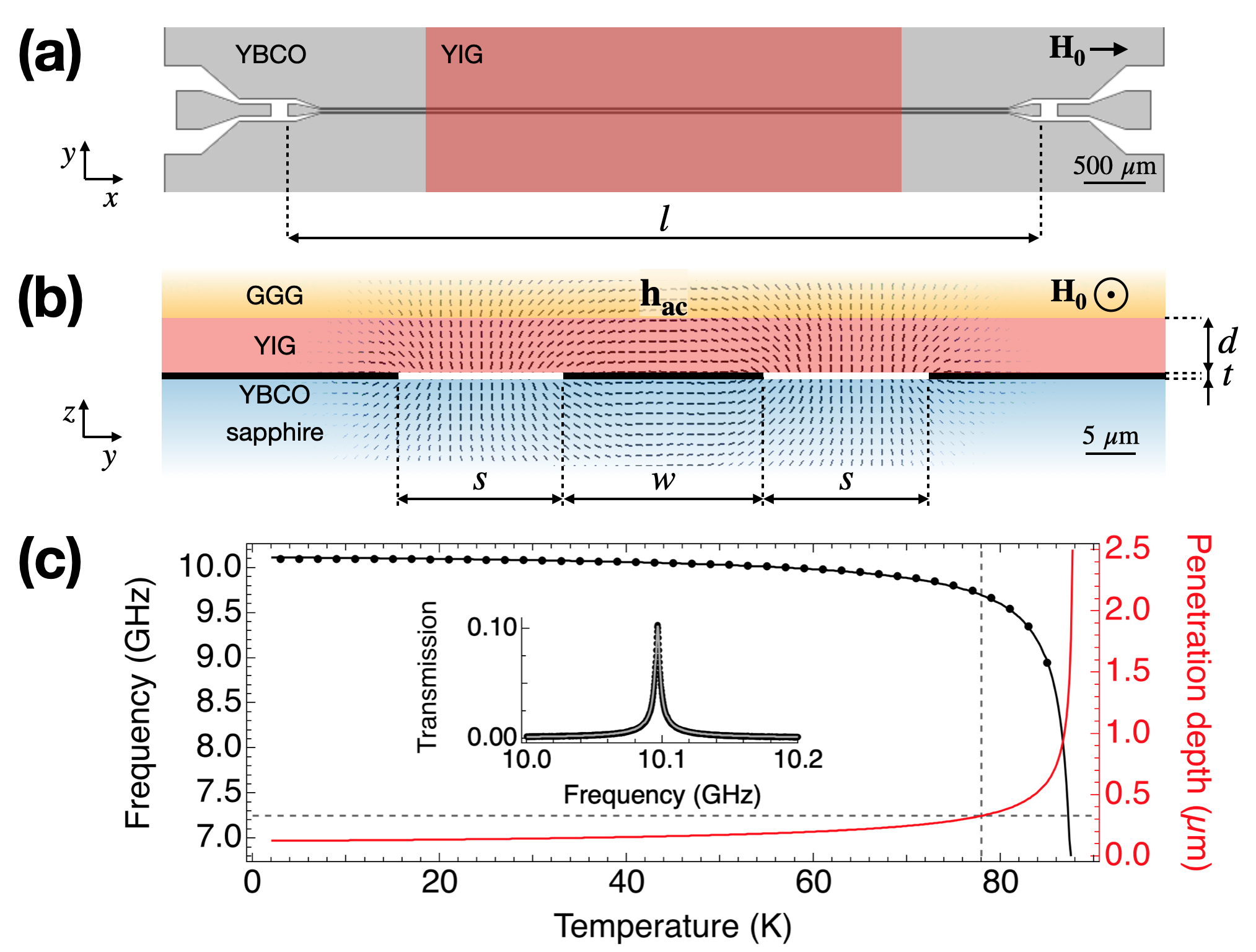
CPW transmission lines and resonators were fabricated by optical lithography starting from superconducting YBCO films (thickness nm) deposited on sapphire sup . The central conductor had width m and separation m from the lateral ground planes; the length was mm (Fig. 1(a,b)). Electromagnetic simulations Ghirri et al. (2023) show that the microwave field is confined within a few tens of above the YBCO surface (Fig. 1(b)). The transmission () spectrum of the bare resonator shows a half-wavelength fundamental mode whose frequency is at the chosen reference temperature K (Inset in Fig. 1(c)). The fundamental mode frequency progressively decreases with increasing temperature up to (Fig. 1(c)).
From the standard theory of distributed element transmission lines, the frequency of the resonator results in , where and are respectively the capacitance and the inductance per unit length, the latter given by the sum of the geometric () and kinetic () contributions. Being weakly depending on the temperature, the dependence can be accounted to the change in the inductance Vendik et al. (1998); Ghigo et al. (2004)
| (1) |
where depends, through , from the penetration depth of the superconductor. In the simplest two-fluid binomial approximation, the latter can be expressed as Prozorov and Giannetta (2006)
| (2) |
where , is the London penetration length in the zero-temperature limit and for d-wave superconductors Prozorov and Giannetta (2006); Vendik et al. (1998); Ghigo et al. (2004). The explicit relation to derive from Eqs. 1 and 2 is reported in sup . The best fit of the experimental data in Fig. 1(c) gives nm and K. These values match well the typical ones reported for high quality YBCO Ghigo et al. (2004). We note that above K the calculated curve exceeds the nominal thickness of the YBCO film (Fig. 1(c)).
A YIG film with thickness m grown on Gadolinium Gallium Garnet substrate (YIG/GGG) was positioned in contact with the YBCO resonator. The external magnetic field was applied in the plane of the superconductor along the direction of the CPW line (). We first carried out transmission measurements by means of a YBCO broadband CPW line, having the same lateral dimensions of the resonator, to investigate the temperature evolution of the spin wave modes in the presence of the superconductor (Fig. 2).
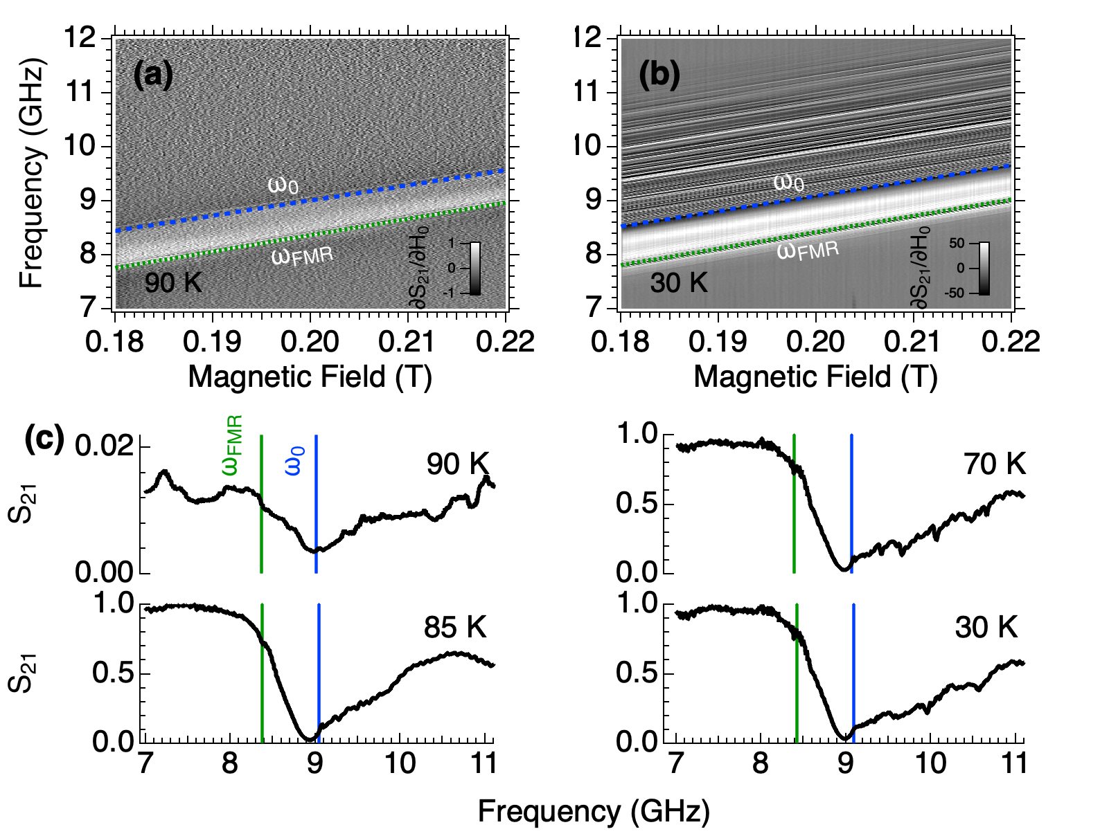
Above we can identify an absorption band with characteristic frequencies (Fig. 2(a)). The lower limit of the band is given by the Kittel relation Kittel (1948)
| (3) |
where and , being H/m the vacuum permeability and the electron’s gyromagnetic ratio. The saturation magnetization of YIG () is assumed to vary with temperature Maier-Flaig et al. (2017) between T and T sup . Note that the minimum of the transmission coincides with the frequency (Fig. 2(a,c)).
CPW lines can excite spin wave modes having wavelength comparable to the lateral profile of the microwave field, Maksymov and Kostylev (2015). For an in-plane bias magnetic field, the direction of propagation is perpendicular to (Fig. 1(b)). In a YIG film, the spectrum of spin wave modes consists of the lowest dipole-dominated mode characterized by a quasi-uniform thickness profile and higher order exchange-dominated modes. The lowest mode approximately follows Kalinikos and Slavin (1986)
| (4) | ||||
whose evolution is similar to what we obtained through the Damon-Eshbach expression Demokritov and Slavin (2021); Ghirri et al. (2023). In Eq. 4, is the wavevector of the spin wave mode in the YIG film and Demokritov and Slavin (2021). As shown in the spectral map in Fig. 2(a), Eq. 4 can reproduce the position of the transmission minimum as a function of the magnetic field. From the direct comparison between and the experimental data, we obtain . This value fits well with what we can estimate from the lateral profile of the CPW line since Maksymov and Kostylev (2015).
The effects of superconductivity on the spin wave resonance spectrum are reflected in the broadband spectral maps below (Fig. 2(b-c)): as the temperature decreases, the absorption band progressively widens, additional resonances can be observed at higher frequencies for while, we note that is nearly temperature independent. In Eq. 4 the temperature dependence is derived from sup . Using the dependence of on can be satisfactorily reproduced in the whole 10-90 K temperature range.
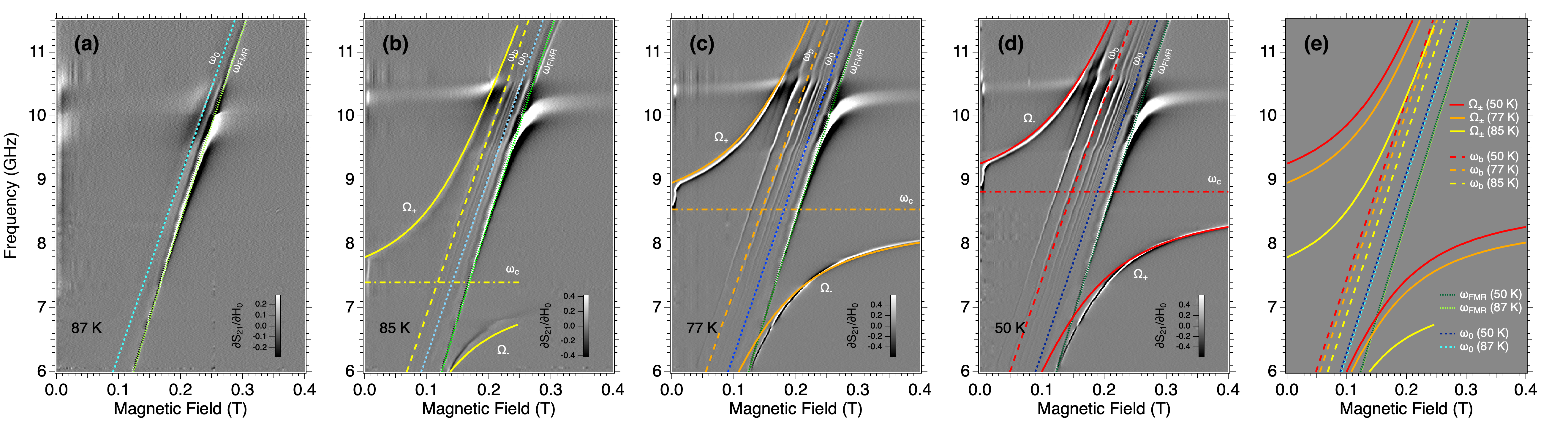
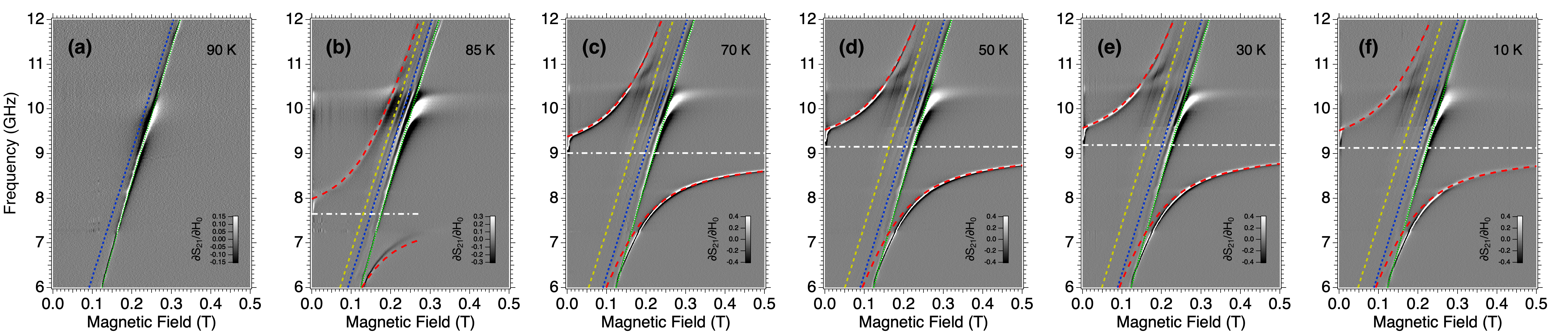
In the following experiments we consider hybridization of spin waves with the fundamental mode of a CPW resonator. To this end, the YIG film was installed on the resonator in the same configuration as for the broadband line as specified before. Fig. 3 shows a series of spectral maps taken at different temperatures. Two datasets were acquired with the same YIG film showing equivalent results sup . At K the resonator mode is not visible but weak absorption lines can be noticed due to the magnetic film. In Fig. 3(a) we can identify the Kittel mode, , and the quasi-uniform thickness mode, . Consistently with data in Fig. 2, the latter can be reproduced with .
At K, the resonator mode appears with frequency GHz (Fig. 3(b)). Due to the permittivity of the YIG/GGG sample, this value is lower than what was obtained at the same temperature using the bare resonator. The spectral map shows the presence of polaritonic branches as a result of the hybridization of spin wave and resonator modes. Note that or modes remain unperturbed across the anticrossing gap, suggesting that their coupling with the resonator mode is weak.
Below 77 K, the fundamental mode frequency increases and the splitting of the polaritonic branches (2) progressively increases up to the maximum value at the lowest temperature (Fig. 3(c,d)). As a common feature of the spectral maps, the lower polaritonic branch merges with , while the increase of the anticrossing splitting is determined by the progressive shift of the upper branch to higher frequencies. This shift of the hybrid magnon-photon mode frequency is certainly related to the vicinity of the superconducting resonator Golovchanskiy et al. (2021b, 2023); Ghirri et al. (2023). If we define as the frequency of the hybrid mode, being the shift estimated with respect to the unperturbed mode frequency , we observe that increases with the lowering of the temperature (see Fig.3(e) and below).
The physical system comprising of resonator modes interacting with collective spin wave excitations can be analysed on the basis of a modified Hopfield Hamiltonian, which adequately describes the hybrid system in the ultrastrong coupling regime Ghirri et al. (2023). The eigenvalues of the Hopfield Hamiltonian reads Ghirri et al. (2023)
| (5) |
where , being the diamagnetic term that, however, we take vanishingly small Ghirri et al. (2023). Assuming that spins are coupled to the resonator mode, the collective coupling strength results in
| (6) |
where is the single-ion spin of Fe3+. The prefactor is spin-photon coupling strength, which can derived from the parameters of the bare resonator Tosi et al. (2014)
| (7) |
being the vacuum magnetic field of the resonator and the nominal impedance of the CPW line.
By means of Eq. 5 we fitted the magnetic field dispersion of the polariton branches measured with the YIG film. In order to reproduce the measured spectral maps in Fig. 3, and were considered free parameters. From the former, was derived using Eq. 7; was calculated (Eq. 6) using the additional parameter , which was assumed to be temperature-independent for each dataset.
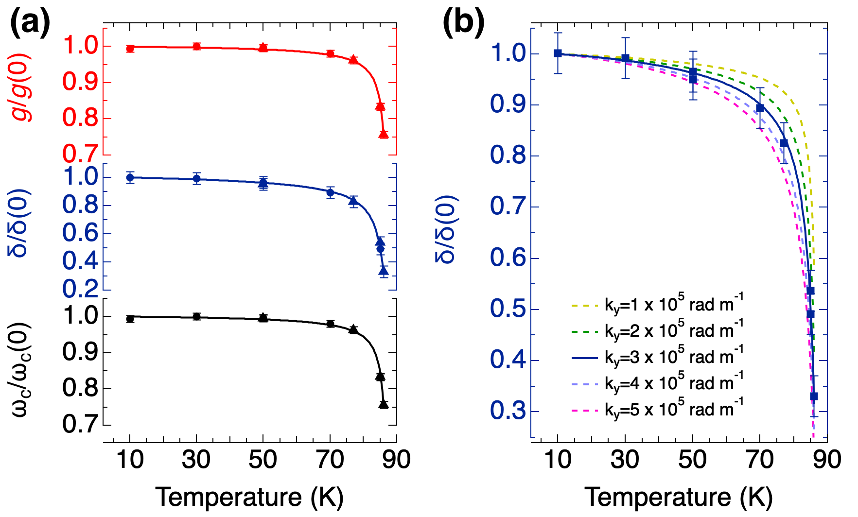
The obtained , and parameters are plotted as a function of the temperature in Fig. 4(a). Note that the maximum value of the coupling strength is GHz, thus resulting larger than one tenth of the mode frequency, confirming that the system is working at the ultrastrong coupling regime Frisk Kockum et al. (2019); Ghirri et al. (2023). The frequency of the resonator mode () can be fitted with Eq. 1 (Fig. 4(a)). In this fitting, and were fixed to the values used for the bare resonator while the best fit was obtained with K. From the calculated curve, the temperature dependence of the collective coupling strength can be determined using Eqs. 7 and 6 by means of (Fig. 4(a)).
Interestingly, the evolution of the frequency shift parameter , shows a well-defined temperature dependence: is small for , conversely for the frequency shift saturates to the maximum value GHz (Fig. 4(a)). Qualitatively, this behavior is similar to the trend reported for superconductor-ferromagnet-superconductor trilayers Golovchanskiy et al. (2023). This temperature dependence of can be linked to the superconductivity of the YBCO film. The frequency of the hybrid magnon-photon mode in the stacked superconducting/magnetic bilayer indeed reflects the presence of the additional magnetic field generated by the superconducting currents, which, in turns, are induced by the precession of the magnetization in the magnetic film. With respect to the unperturbed spin wave mode , the frequency of the hybrid mode is .
In the two-fluid model of the superconductor, the dissipation due to normal electrons is related to the real part of the complex conductivity . For YBCO films with thickness on the order of few hundred nanometers, the expected ratio is of the order of one tenth or less just below Krupka et al. (2013); sup . Thus, if we neglect dissipative effects sup , the frequency shift can be quantified by self-consistently including the (”Meissner”) field generated by the adjacent superconductor in the Landau-Lifshitz-Gilbert equation Borst et al. (2023):
| (8) |
In our case, we used as obtained from the spectra in Fig. 2 and 3. The dimensionless factor depends on the experimental conditions Borst et al. (2023) and its main effect is to scale the absolute value of the curve. We note that the temperature dependence of Eq. 8 mainly derives from the temperature dependence of the penetration depth (Eq. 2) and, partially from the weak temperature dependence of the saturation magnetization in this range sup .
By considering (Eq. 2) and the previously reported values of , and , the temperature dependence of the frequency shift can be successfully reproduced as shown in Fig. 4(a). We stress that the only free parameter used in this case is , which has been chosen to adapt the absolute value of the curve to the points at low temperatures. We note that the curves, calculated with the fitted parameters, reproduce the evolution of a specific mode in Fig. 3(a-d) demonstrating the self-consistency of our approach. To further test the comparison between Eq. 8 and the values derived from the fit, Fig. 4(b) displays the dependence for different wavenumbers . The excellent match with further confirms the consistency of our results.
To summarize, we studied the evolution of transmission spectra in a hybrid magnon-photon system implemented with a bilayer stack of insulating YIG film and a high- YBCO resonator. We correlated the temperature dependence of the characteristic parameters derived from the polaritonic branches to the temperature dependence of the penetration depth. The latter essentially governs the frequency of the resonator and the coupling strength, as well as the frequency shift respect to the unperturbed spin wave mode. The excellent agreement between the experimental findings and the fitting curves confirms the efficiency of the two-fluid model to account for the non-dissipative interplay between magnetic excitations and an adjacent superconducting layer. Line broadening or microscopic visualization of the mixed state of the superconductor will certainly require to consider dissipative effects that can be included in the LLG equation at least in a phenomenological way Borst et al. (2023). Considering the recently demonstrated possibility to exploit the diamagnetism of superconductors to gate the wave propagation in planar magnonic devices, we foresee the possibility to use high- superconductors operating at liquid nitrogen temperatures.
Acknowledgements.
This work was partially supported by the European Community through FET Open SUPERGALAX project (grant agreement No. 863313); by NATO Science for Peace and Security Programme (NATO SPS Project No. G5859) and by US. Office of Naval Research award N62909-23-1-2079.References
- Golovchanskiy et al. (2018) I. A. Golovchanskiy, N. N. Abramov, V. S. Stolyarov, V. V. Ryazanov, A. A. Golubov, and A. V. Ustinov, Journal of Applied Physics 124, 233903 (2018).
- Yu and Bauer (2022) T. Yu and G. E. W. Bauer, Phys. Rev. Lett. 129, 117201 (2022).
- Borst et al. (2023) M. Borst, P. H. Vree, A. Lowther, A. Teepe, S. Kurdi, I. Bertelli, B. G. Simon, Y. M. Blanter, and T. van der Sar, Science 382, 430 (2023).
- Zhou and Yu (2023) X.-H. Zhou and T. Yu, Phys. Rev. B 108, 144405 (2023).
- Dobrovolskiy et al. (2019) O. V. Dobrovolskiy, R. Sachser, T. Brächer, T. Böttcher, V. V. Kruglyak, R. V. Vovk, V. A. Shklovskij, M. Huth, B. Hillebrands, and A. V. Chumak, Nature Physics 15, 477 (2019).
- Ghirri et al. (2015) A. Ghirri, C. Bonizzoni, D. Gerace, S. Sanna, A. Cassinese, and M. Affronte, Applied Physics Letters 106, 184101 (2015).
- Bonizzoni et al. (2020) C. Bonizzoni, A. Ghirri, F. Santanni, M. Atzori, L. Sorace, R. Sessoli, and M. Affronte, npj Quantum Information 6, 68 (2020).
- Artzi et al. (2022) Y. Artzi, Y. Yishay, M. Fanciulli, M. Jbara, and A. Blank, Journal of Magnetic Resonance 334, 107102 (2022).
- Bonizzoni et al. (2023) C. Bonizzoni, M. Maksutoglu, A. Ghirri, J. van Tol, B. Rameev, and M. Affronte, Applied Magnetic Resonance 54, 143 (2023).
- Ghirri et al. (2016) A. Ghirri, C. Bonizzoni, F. Troiani, N. Buccheri, L. Beverina, A. Cassinese, and M. Affronte, Phys. Rev. A 93, 063855 (2016).
- Bonizzoni et al. (2017) C. Bonizzoni, A. Ghirri, M. Atzori, L. Sorace, R. Sessoli, and M. Affronte, Scientific Reports 7, 13096 (2017).
- Velluire-Pellat et al. (2023) Z. Velluire-Pellat, E. Maréchal, N. Moulonguet, G. Saïz, G. C. Ménard, S. Kozlov, F. Couëdo, P. Amari, C. Medous, J. Paris, R. Hostein, J. Lesueur, C. Feuillet-Palma, and N. Bergeal, Scientific Reports 13, 14366 (2023).
- (13) Supplemental material .
- Chumak et al. (2022) A. V. Chumak, P. Kabos, M. Wu, C. Abert, C. Adelmann, A. O. Adeyeye, J. Åkerman, F. G. Aliev, A. Anane, A. Awad, C. H. Back, A. Barman, G. E. W. Bauer, M. Becherer, E. N. Beginin, V. A. S. V. Bittencourt, Y. M. Blanter, P. Bortolotti, I. Boventer, D. A. Bozhko, S. A. Bunyaev, J. J. Carmiggelt, R. R. Cheenikundil, F. Ciubotaru, S. Cotofana, G. Csaba, O. V. Dobrovolskiy, C. Dubs, M. Elyasi, K. G. Fripp, H. Fulara, I. A. Golovchanskiy, C. Gonzalez-Ballestero, P. Graczyk, D. Grundler, P. Gruszecki, G. Gubbiotti, K. Guslienko, A. Haldar, S. Hamdioui, R. Hertel, B. Hillebrands, T. Hioki, A. Houshang, C.-M. Hu, H. Huebl, M. Huth, E. Iacocca, M. B. Jungfleisch, G. N. Kakazei, A. Khitun, R. Khymyn, T. Kikkawa, M. Kläui, O. Klein, J. W. Kłos, S. Knauer, S. Koraltan, M. Kostylev, M. Krawczyk, I. N. Krivorotov, V. V. Kruglyak, D. Lachance-Quirion, S. Ladak, R. Lebrun, Y. Li, M. Lindner, R. Macêdo, S. Mayr, G. A. Melkov, S. Mieszczak, Y. Nakamura, H. T. Nembach, A. A. Nikitin, S. A. Nikitov, V. Novosad, J. A. Otálora, Y. Otani, A. Papp, B. Pigeau, P. Pirro, W. Porod, F. Porrati, H. Qin, B. Rana, T. Reimann, F. Riente, O. Romero-Isart, A. Ross, A. V. Sadovnikov, A. R. Safin, E. Saitoh, G. Schmidt, H. Schultheiss, K. Schultheiss, A. A. Serga, S. Sharma, J. M. Shaw, D. Suess, O. Surzhenko, K. Szulc, T. Taniguchi, M. Urbánek, K. Usami, A. B. Ustinov, T. van der Sar, S. van Dijken, V. I. Vasyuchka, R. Verba, S. V. Kusminskiy, Q. Wang, M. Weides, M. Weiler, S. Wintz, S. P. Wolski, and X. Zhang, IEEE Transactions on Magnetics 58, 1 (2022).
- Huebl et al. (2013) H. Huebl, C. W. Zollitsch, J. Lotze, F. Hocke, M. Greifenstein, A. Marx, R. Gross, and S. T. B. Goennenwein, Phys. Rev. Lett. 111, 127003 (2013).
- Zare Rameshti et al. (2022) B. Zare Rameshti, S. Viola Kusminskiy, J. A. Haigh, K. Usami, D. Lachance-Quirion, Y. Nakamura, C.-M. Hu, H. X. Tang, G. E. Bauer, and Y. M. Blanter, Physics Reports 979, 1 (2022).
- Golovchanskiy et al. (2021a) I. A. Golovchanskiy, N. N. Abramov, V. S. Stolyarov, M. Weides, V. V. Ryazanov, A. A. Golubov, A. V. Ustinov, and M. Y. Kupriyanov, Science Advances 7, eabe8638 (2021a).
- Golovchanskiy et al. (2021b) I. Golovchanskiy, N. Abramov, V. Stolyarov, A. Golubov, M. Y. Kupriyanov, V. Ryazanov, and A. Ustinov, Phys. Rev. Applied 16, 034029 (2021b).
- Silaev (2023) M. Silaev, Phys. Rev. B 107, L180503 (2023).
- Ghirri et al. (2023) A. Ghirri, C. Bonizzoni, M. Maksutoglu, A. Mercurio, O. Di Stefano, S. Savasta, and M. Affronte, Phys. Rev. Appl. 20, 024039 (2023).
- Frisk Kockum et al. (2019) A. Frisk Kockum, A. Miranowicz, S. De Liberato, S. Savasta, and F. Nori, Nature Reviews Physics 1, 19 (2019).
- Hein (1999) M. Hein, High-Temperature-Superconductor Thin Films at Microwave Frequencies (Springer, Berlin, 1999).
- Vendik et al. (1998) O. Vendik, I. Vendik, and D. Kaparkov, IEEE Transactions on Microwave Theory and Techniques 46, 469 (1998).
- Ghigo et al. (2004) G. Ghigo, D. Botta, A. Chiodoni, R. Gerbaldo, L. Gozzelino, F. Laviano, B. Minetti, E. Mezzetti, and D. Andreone, Superconductor Science and Technology 17, 977 (2004).
- Prozorov and Giannetta (2006) R. Prozorov and R. W. Giannetta, Superconductor Science and Technology 19, R41 (2006).
- Kittel (1948) C. Kittel, Phys. Rev. 73, 155 (1948).
- Maier-Flaig et al. (2017) H. Maier-Flaig, S. Klingler, C. Dubs, O. Surzhenko, R. Gross, M. Weiler, H. Huebl, and S. T. B. Goennenwein, Phys. Rev. B 95, 214423 (2017).
- Maksymov and Kostylev (2015) I. S. Maksymov and M. Kostylev, Physica E: Low-dimensional Systems and Nanostructures 69, 253 (2015).
- Kalinikos and Slavin (1986) B. A. Kalinikos and A. N. Slavin, Journal of Physics C: Solid State Physics 19, 7013 (1986).
- Demokritov and Slavin (2021) S. O. Demokritov and A. N. Slavin, “Spin waves,” in Handbook of Magnetism and Magnetic Materials, edited by J. M. D. Coey and S. S. Parkin (Springer International Publishing, Cham, 2021) pp. 281–346.
- Golovchanskiy et al. (2023) I. Golovchanskiy, N. Abramov, O. Emelyanova, I. Shchetinin, V. Ryazanov, A. Golubov, and V. Stolyarov, Phys. Rev. Appl. 19, 034025 (2023).
- Tosi et al. (2014) G. Tosi, F. A. Mohiyaddin, H. Huebl, and A. Morello, AIP Advances 4, 087122 (2014).
- Krupka et al. (2013) J. Krupka, J. Wosik, C. Jastrzebski, T. Ciuk, J. Mazierska, and M. Zdrojek, IEEE Transactions on Applied Superconductivity 23, 1501011 (2013).
- Solt (2004) J. Solt, Irvin H., Journal of Applied Physics 33, 1189 (2004).
- Lancaster (1997) M. J. Lancaster, Passive Microwave Device Applications of High-Temperature Superconductors (Cambridge University Press, 1997).
Supplemental material
.1 Methods
Coplanar waveguide (CPW) resonators and transmission lines were fabricated starting from Au (200 nm)/YBCO (330 nm)/sapphire (430 m) films produced by Ceraco GmbH (M-type) and diced into chips. Planar devices were fabricated by optical lithography and etching with Ar plasma in a reactive ion etching (RIE) chamber. The YBCO surface was exposed to an oxygen plasma as a final step of the fabrication procedure. Gold pads defined at the edge of the chip were used to facilitate the bonding to an external printed circuit board.
Transmission spectra were acquired as a function of the microwave frequency by means of a vector network analyzer. The estimated incident power considering line attenuation is dBm. The YIG/GGG film was placed on the YBCO surface and kept in position thanks to a plastic screw that gently pushed the GGG substrate from the backside Ghirri et al. (2023). The experiments were carried out in a variable temperature cryostat equipped with a superconducting solenoid and coaxial lines, whose insertion loss was removed from transmission data.
.2 Temperature dependence of the saturation magnetization
.3 Modelization of the CPW resonator
To transmission spectrum of the CPW resonators can be reproduced with Hein (1999)
| (2) |
where is the fundamental mode frequency, is the loaded quality factor and is the insertion loss. The values obtained at 10 K are GHz, and dB (Inset in Fig. 1(c) of the Letter).
Following Ref. Ghigo et al. (2004), the temperature dependence of the frequency of the resonator () can be evaluated as
| (3) |
where and K. Here and are respectively the inductance and the capacitance per unit length. By neglecting the weak temperature variations of the latter Ghigo et al. (2004), we obtain
| (4) |
being and the geometric and kinetic inductance per unit length, respectively. The geometric inductance is temperature independent and reads Lancaster (1997)
| (5) |
where is the complete elliptic integral and . Conversely, the kinetic inductance depends on the temperature through the penetration depth (Eq. 2 in the Letter). For a CPW line, can be written as Vendik et al. (1998)
| (6) |
where
| (7) |
The expressions for the coefficients and are
| (8) | ||||
| (9) |
and
| (10) | ||||
| (11) |
being Ghigo et al. (2004).
.4 Dissipation and decay of the magnetic field in the superconducting layer
According to the two-fluid model, the conductivity of the superconductor is , where is responsible for the dissipation and fully describes the conductivity above , while is responsible for the kinetic inductance. In the normal state the skin depth of the electromagnetic field can be defined as .
Data reported in ref. Krupka et al. (2013) for 280 nm thick YBCO/sapphire films at 28.2 GHz, indicate that is in the range between and S/m, while rapidly increases from S/m at to saturate at S/m at 13 K. The ratio results between 0.33 and 0.12 from to 83 K, and lower than 0.1 below 83 K. In our experiment, we expect even lower ratios due to the higher thickness of the film ( nm) and to the lower frequency of the resonator, . We thus neglect and assume that the complex conductivity is as in the case of a perfect superconductor.
Within the superconducting layer, the decay constant of the magnetic field generated by the spin wave is Borst et al. (2023)
| (12) |
where is the fractional number density of normal electrons. The estimated skin depth results at 10 GHz, thus much larger than both the penetration depth in the superconducting state (Fig. 1(c) of the Letter) and the thickness of the YBCO layer. By neglecting the second term under the square root, Eq. 12 results thus, considering that in our experiment , we finally obtain .
.5 Additional transmission spectroscopy data
Transmission spectra were acquired with a YIG/GGG film having area , which was positioned in the middle of the YBCO resonator. We collected two datasets in different experimental runs; the measured spectral maps are shown in Fig. 3 of the Letter and in Fig. S1. The two datasets show very similar features, the only small differences in the absolute value of frequencies and coupling strengths can be attributed to the slightly different positioning of the YIG film in the two experiments.