Gate-tunable graphene Josephson diode effect due to magnetochiral anisotropy
Abstract
Usually the magnetochiral anisotropy related Josephson diode effect is assumed to be based on conventional two-dimensional electron gas, such as the InAs quantum well. Here we propose a graphene-based Josephson junction as a broadly gate-tunable platform for achieving nonreciprocal supercurrent within the context of magnetochiral anisotropy. We show that the resulting nonreciprocal supercurrents will exhibit a sign reversal when the graphene switches from -type doping to -type doping. Particularly, the magnitude of the nonreciprocity is highly sensitive to the electrostatic doping level of graphene, enabling gate control of the diode efficiency from zero up to approximately . This giant gate-tunability stems from the chiral nature of the pseudo-relativistic carriers in grapehe, allowing the graphene Josephson diode emerges as a promising element for advanced superconducting circuits and computation devices. Moreover, we have also obtained the so-called -like phase transitions in the current-phase relation, in coincidence with recent experimental finding.
Introduction.—
Nonreciprocal transport refers to a phenomenon by which the different resistance for electric currents traversing in different (opposite) directions, i.e., . When both time-reversal and inversion symmetry are simultaneously broken in spatially symmetric devices, a closely related phenomenon leading to nonlinear nonreciprocal response is known as the magnetochiral anisotropy (MCA) ref1 ; ref2 ; ref3 . This can be obtained, for example, by applying an out-of-plane electric field and an in-plane magnetic field B. As and B are orthogonal to each other and to the direction along which current is traversing, the current-dependent resistance can be described as , where is the MCA rectification coefficient depending on the Rashba spin-orbit coupling (RSOC) strength ref4 .
The MCA related nonreciprocity has also been observed in noncentrosymmetric superconductors under magnetic fields, where the resulting nonreciprocal supercurrent is known as the superconducting diode effect (SDE) characteristic by finite momentum Cooper pairing ref5 . The SDE allows for a larger critical supercurrent in one direction than in the opposite, offering numerous novel device applications in superconducting spintronics and quantum computing technology ref6 . Similarly, the MCA could also induce SDE in superconducting-normal-superconducting (SNS) Josephson junctions, a phenomenon referred to as the Josephson diode effect (JDE) ref7 ; ref8 ; ref9 ; ref10 .
From the microscopic point of view, JDE is more conveniently described by Andreev bound states (ABSs) ref11 ; ref12 ; ref12-1 ; ref13 . These bound states, in the presence of Zeeman coupling and resonant spin-orbital coupling (RSOC), modify the current-phase relation (CPR), imparting an anomalous phase shift () ref14 ; ref15 ; ref16 . Such a phase shift leads to a marked asymmetry of the CPR, that is, . In addition to the -phase shift, another essential component required to exhibit the diode effect is a skewed CPR, namely, a CPR with higher harmonics, as those observed in short-ballistic junctions with high transparencyref17 . To be more specific, the Fourier expansion of the CPR can be written as
| (1) |
where and decrease with . The combination of RSOC and in-plane Zeeman field will enhance the even terms [i.e., component] owing to the broken inversion and time-reversal symmetries ref18 . In order to obtain the JDE, it is concurrently essential that the coefficients should be non-zero for , and not too small compared to . That is, the CPR must be skewed already in zero in-plane field.
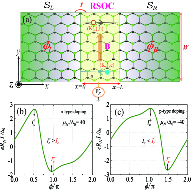
Experimentally, the JDE was first realized by Baumgartner et al. in a symmetric Al/InAs/Al junction ref19 . Hitherto, all the reported MCA related Josephson diodes have been fabricated based on conventional two-dimensional electron gas (2DEG) ref18 ; ref19 ; ref20 ; ref21 , where the gate-tunability of the diode efficiency is not immediately evident. In this letter, we propose a graphene SNS junction as a new platform for achieving JDE in the context of MCA effect, which is feasible in an actual tunneling experiment, since the enhanced RSOC and Zeeman coupling in graphene have been achieved by means of the proximity effect ref22 ; ref23 ; ref24 ; ref25 ; ref26 ; ref27 ; ref28 ; ref29 . As illustrated in Fig. 1(a), a tunable gate voltage can be applied in the non-superconducting graphene region (N region) to modulate the electrostatic doping. In Figs. 1(b) and 1(c), one can observe that the nonreciprocal critical currents ( and ) between the -type and -type doped cases are opposite, suggesting a promising way to manipulate the JDE by switching the charge carrier type through electrostatic gating. As we will also demonstrate in the following text, such a graphene-based Josephson diode contains giant gate-tunability due to the pseudo-relativistic chiral property of Dirac fermions in graphene, setting it apart from conventional 2DEG systems. We also emphasize that the underling physical mechanism behind the JDE proposed here is not the finite Cooper pair momentum, but rather the phase interference between the first-order and second-order harmonics.
Model and formalism.—
Our starting point is the nearest-neighbor tight-binding Hamiltonian of the central N region that incorporates both effects of RSOC and in-plane Zeeman field ref30 ; ref31
| (2) | ||||
where is the electron creation annihilation operator with spin on site , is the Pauli matrix describing the electron’s spin, and the angular bracket stands for a pair of nearest-neighboring sites. The first term represents the nearest-neighbor hopping with hoping energy . The second term describes the chemical potential. We will assume that the chemical potential in the superconducting regions, denoted as , is rather large and constant due to the external contacts, while in the N region, the doping level can be varied arbitrarily with a local back-gate denoted by ref32 ; ref33 ; ref34 . The third term is the Zeeman coupling induced by an in-plane magnetic-field directed in the direction. Although the factor in graphene is much smaller than in Rashba nanowires, the magnetic-field-induced Zeeman field has been achieved in graphene with considerable magnitudes through a strong exchange coupling with a magnetic insulator, such as EuS under an applied magnetic field ref27 ; ref28 ; ref29 . The fourth term represents the extrinsic RSOC associated with the nearest-neighbor hopping. The vector represents the unit vector connecting two sites and . Experimentally, the coupling strength can arise up to the order of 10 meV by growing graphene on Ni(111) intercalated with a Au layer or proximity to high SOC transition-metal dichalcogenides ref23 ; ref24 ; ref25 ; ref26 .
In the two superconducting regions, an on-site -wave pair potential of is introduced by proximity to external superconducting contacts ref35 ; ref35-1 , but the RSOC and Zeeman coupling are absent. Here, denotes the left (right) lead. The temperature dependence of the BCS gap reads with being the zero-temperature superconducting gap and being the critical temperature. In addition, denotes the phase of pair potential in the superconducting lead. In our numerical calculation, the hopping energy is set to be eV for the sake of simplicity, the pair potential at zero temperature is fixed at and taken as the energy unit of parameters. In the numerical treatment, we assume clean, smooth interfaces, allowing a Fourier transform along the direction parallel to the interface is applicable. In addition, the type of interface can vary, but having an in-situ pairing ensures that the direction of the interface is immaterial. We will here use the armchair-type interface and one unit cell is long.
The supercurrent through -th column in the central N region can be evaluated by the recursion Green’s function as follows ref36 ; ref37 :
| (3) | ||||
where is the transverse momentum with being an integer since the junction width is assumed to be lagre enough () ref37-1 , denotes the charge matrix, is the third Pauli matrix in Nambu space, and is the unit matrix in the spin space. is the Hamiltonian matrix element, representing the coupling between the -th and -th layer in the N region. The lesser-than Green’s function in the equilibrium state satisfies with being the Fermi-Dirac distribution function. The retarded and advanced Green’s functions read , where is the Hamiltonian of the N region. The retarded self-energy due to the coupling with the region could be obtained by the recursive method ref38 ; ref39 . Similar to the supercurrent, the ABS spectra can also be numerically calculated using the Green’s function method. Since the ABSs correspond to particle density peaks within the superconducting gap, the energy levels of ABSs can be located by searching the peaks of the particle density at column in the central N region
| (4) |
at a given macroscopic superconducting phase difference .
Band structures and ABS spectra.—
Here we are only interested in the transport channels near the Dirac points with low-energy electron dispersion. In the weak limit of magnetic field , this spectrum is can be formulated as
| (5) |
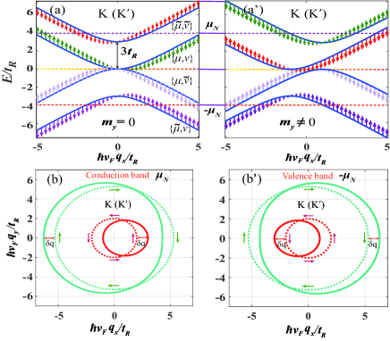
where is the momentum measured from the and points so that , represents the effective strength of the RSOC, , is the band indices and is the Fermi velocity, given by with a value . The corresponding electronic spectrum consists of four energy bands, which are plotted in Fig. 2(a). In our notation, we define and , such that or refers to the conduction bands while or refers to the valence bands. The in-plane spin polarizations are determined by the expectation values of in the state for is given by ref43
| (6) |
S depends on the wave vector and is proportional to the group velocity . The sign of in Eq. (7) signifies the helical direction of the spin textures, which is identical for valleys and . In a -direction in-plane Zeeman field, each subband is shifted in energy, , rendering the MAC effect of the energy spectrum. The magnitude of the momentum shift is estimated by its Fermi-surface average,
| (7) |
with being the unit direction vector point to the -axis. Such a momentum shift will result in a remarkable Cooper pair momentum during the Andreev reflection process within each FS, leading to a phase shift for the related ABS, as shown in Fig. 3.
In the short junction limit , the two FS-resolved ABSs at are-in a rough approximation-simulated as ref12 ; ref12-1 ; ref13
| (8) |
where is the transmission probability for normal-state electrons to tunnel through the junction in channels with a state , denotes the extra shift phase resulting from the momentum change of , Due to the opposite momentum shifts between the two spin-splitting FSs, the two FS-resolved ABSs experience opposite phase shifts. The phase derivative of the ABS spectra eventually defines the CPR ref44 ; ref45 :
| (9) |
Let us first consider the case of -type doping, where the Fermi level locates at the conduction bands with two subbands and . Then the total current can be expressed as . Both and can be decomposed into a series of different orders of harmonics with an anomalous shift of each term:
| (10) | ||||
where the higher-order sine terms with have been neglected. We notice that the signs of phase shifts are opposite between and , i.e., . This phase shift is essentially equivalent to the cosine term in Eq. (1). The second order sine term is sensitive to graphene’s electrostatic doping level and determines the skewedness of CPR, deviating significantly from a simple sinusoidal form. It should be emphasized that the RSOC gap, i.e., , is specific to graphene and could act as a spin-dependent potential that affects the spin-splitting ABS , resulting in the amplitude difference between and . Consequently, the total CPR has the form of . Here, the relative phase difference between the and , given by , plays a crucial role in the JDE. This difference is explicitly determined by both the -induced momentum shift and the RSOC-induced spin-splitting gap.
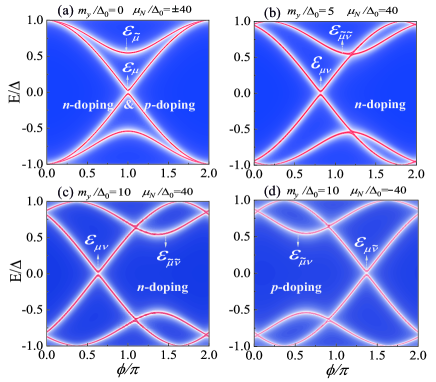
On the contrary, the Fermi level in -doped graphene is now located in valence bands indicated by and . As illustrated in Fig. 2(b’), the Zeeman shifts for the valence bands always contrasts to that in the conduction bands, resulting in opposite phase shifts. In this scenario, we can describe the total CPR as where the sign of has been changed when compared to the -doped case. It follows that the nonreciprocity-related factor will also change sign and then reverses the diode effect, leading to instead of . Such a sign reversal can be also interpreted by the phase-dependent free energy that can be found in the Supplemental Material.
Evolution of CPR and Quality factor. —
Now we proceed to analysis the evolution of CPRs by varying , as shown in Fig. 4(a). We have made the simplifying assumption that the doping profile changes abruptly from to at the interface. To ensure the validity of our results, we limit our analysis to meV, which has been experimentally verified to be feasible. It is evident that at appears as a nearly sinusoidal function with an additional slight phase shift, namely, with . Actually, the diode effect is usually not apparent in the weak doping limit () wherein both the two spin-splitting channels are in the low limit due to the nearly zero carrier density. In this regime, the higher harmonics and the associated skewedness of CPR are strongly suppressed, thereby alleviating the diode effect. Interestingly, increasing can significantly enhance terms in Eq. (13), resulting in a remarkable enhancement of the diode effect. Such an enhancement becomes even clearer when plotting the diode quality factor as a function of shown in Fig. 4(c). The symmetry relation and is satisfied and is highly sensitive to the electrostatic doping level as well as . It might be worth mentioning here that remains zero at regardless of the change in , which is a direct consequence of the vanishing of all at the Dirac points. The diode quality increases linearly with increasing , and can be as large as at a moderate doping level. This suggests that our proposed setup contains a large gate-tunability, making it an ideal material for designing electrically tunable JDEs with numerous benefits for practical superconducting diode devices.
However, will be drastically reduced when is larger than some critical values (e.g., ). It is reasonable to speculate that in the large limit of , i.e., , the RSOC would play only a very minor role for the total Josephson current.
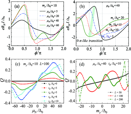
To further illustrate the evolution of the quality factor with the variation of parameters, in Fig. 4(d), we show the dependence of as a function of for serval junction lengths count by the number of the unit cell (1 unit cell ). Similar to the case of varying , one can see that the nonreciprocity efficiency is also an odd function of , namely, . The magnitude of depends strongly on the Zeeman coupling strength. In the context of a very short junction length, e.g., , the diode effect shows a linear increase with within a relatively large range. However, this is not the case for moderate junction length, e.g., , in that periodic sign reversals of can be found with the increase in . This can be intuitively understood from the -like phase transition at relatively large Zeeman field as illustrated in Fig. 4(b). More precisely, the phase shift of is proportional to the production of and , i.e., . When is large enough that equals approximately , the SNS junction might undergo current-reversing -like phase transitions, leading to sign changes of . These phase transition associated sign reversals are in coincidence with the recently conducted Josephson diode experiment based on 2DEG under large in-plane fields. However, we emphasize that the undamped-periodic oscillation of observed in Fig. 4(d) can be significantly distinguished from the 2DEG system ref20 . More details on the evolution of the system’s ground states can be found in the Supplementary Information.
Conclusions —
We have studied the nonreciprocal transport in a graphene Josephson junction under the magnetochiral mechanism. Our results reveal that the graphene Josephson diode exhibits giant gate-tunability, including the sign reversal by switching the graphene’s doping type. Such an advantage may pave the way for applications of graphene in the field of the superconducting diode.
References
- (1) Y. Tokura and N. Nagaosa, Nat. Commun. 9, 3740 (2018).
- (2) P. He, S. S. L. Zhang, D. Zhu, Y. Liu, Y. Wang, J. Yu, G. Vignale, and H. Yang, Nat. Phys. 14, 495 (2018).
- (3) Y. Wang, H. F. Legg, T. Bömerich, J. Park, S. Biesenkamp, A. A. Taskin, M. Braden, A. Rosch, and Y. Ando, Phys. Rev. Lett. 128, 176602 (2022).
- (4) T. Ideue, K. Hamamoto, S. Koshikawa, M. Ezawa, S. Shimizu, Y. Kaneko, Y. Tokura, N. Nagaosa, and Y. Iwasa, Nat. Phys. 13, 578 (2017).
- (5) F. Ando, Y. Miyasaka, T. Li, J. Ishizuka, T. Arakawa, Y. Shiota, T. Moriyama, Y. Yanase, and T. Ono, Nature (London) 584, 373 (2020).
- (6) M. Nadeem, M. S. Fuhrer, and X.-L. Wang, Nat. Rev. Phys. 5, 558-577 (2023).
- (7) J. Hu, C. Wu, and X. Dai, Phys. Rev. Lett. 99, 067004 (2007).
- (8) T. Yokoyama, M. Eto, and Y. V. Nazarov, Phys. Rev. B 89, 195407 (2014).
- (9) Y. Zhang, Y. Gu, P. Li, J. Hu, and K. Jiang, Phys. Rev. X 12, 041013 (2022).
- (10) A. Costa, J. Fabian, and D. Kochan, Phys. Rev. B 108, 054522 (2023).
- (11) A. F. Andreev, Zh. Eksp. Teor. Fiz. 49, 655 (1966). J. Exp. Theor. Phys. 22, 455-458 (1966).
- (12) C. W. J. Beenakker, Phys. Rev. Lett. 67, 3836 (1991).
- (13) A. Costa, J. Fabian, and D. Kochan, Phys. Rev. B 98, 134511 (2018).
- (14) M. Davydova, S. Prembabu, and L. Fu, Sci. Adv. 8, eabo0309 (2022).
- (15) D. B. Szombati, et al., Nat. Phys. 12, 568-572 (2016).
- (16) W. Mayer, et al, Nat. Commun. 11, 212 (2020).
- (17) E. Strambini, et al., Nat. Nanotechnol. 15, 656-660 (2020).
- (18) A. A. Golubov, M. Yu. Kupriyanov, and E. Il’ichev, Rev. Mod. Phys. 76, 411 (2004).
- (19) C. Baumgartner, et al., J. Phys.: Condens. Matter 34, 154005 (2022).
- (20) C. Baumgartner, L. Fuchs, A. Costa, S. Reinhardt, S. Gronin, G. C. Gardner, T. Lindemann, M. J. Manfra, P. E. Faria Junior, D. Kochan, J. Fabian, N. Paradiso, and C. Strunk, Nat. Nanotechnol. 17, 39 (2022).
- (21) A. Costa, et al., Nat. Nanotechnol. 10.1038/s41565-023-01451-x (2023).
- (22) S. Reinhardt, et al., Preprint at arXiv https://www.arxiv.org/abs/2308.01061v1.
- (23) A. Varykhalov, J. Sanchez-Barriga, A. M. Shikin, C. Biswas, E. Vescovo, A. Rybkin, D. Marchenko and O. Rader, Phys. Rev. Lett. 101, 157601 (2008).
- (24) D. Marchenko, A. Varykhalov, M. R. Scholz, G. Bihlmayer, E. I. Rashba, A. Rybkin, A. M. Shikin, and O. Rader Nat. Commun. 3, 1232 (2012).
- (25) A. Avsar, J. Y. Tan, T. Taychatanapat, J. Balakrishnan, G. K. W. Koon, Y. Yeo, J. Lahiri, A. Carvalho, A. S. Rodin, E. C. T. OFarrell, G. Eda, A. H. Castro Neto, and B. Ozyilmaz, Nat. Commun. 5, 4875 (2014).
- (26) M. Gmitra and J. Fabian, Phys. Rev. B 92, 155403 (2015).
- (27) Z. Wang, D. K. Ki, H. Chen, Berger H, A. H. MacDonald, and A. F. Morpurgo, Nat. Commun. 6, 8339 (2015).
- (28) P. Wei, S. Lee, F. Lemaitre, L. Pinel, D. Cutaia, W. Cha, F. Katmis, Y. Zhu, D. Heiman, J. Hone, et al., Nature Mater. 15, 711 (2016).
- (29) Z.-H. Wang, E. V. Castro, and H.-Q. Lin, Phys. Rev. B 97, 041414(R) (2018).
- (30) C.-C. Tseng et al., Nano Lett. 22, 8495-8501 (2022).
- (31) C. L. Kane and E. J. Mele, Phys. Rev. Lett. 95, 146802 (2005).
- (32) Z.-H. Qiao et al., Phys. Rev. B 82, 161414(R) (2010).
- (33) A. H. Castro Neto, F. Guinea, N. M. R. Peres, K. S. Novoselov, and A. K. Geim, Rev. Mod. Phys. 81, 109 (2009).
- (34) C. W. J. Beenakker, Rev. Mod. Phys. 80, 1337 (2008).
- (35) W. Kim, J. Riikonen, C. Li, Y. Chen, and H. Lipsanen, Nanotechnology 24, 395202 (2013).
- (36) G. Nanda, et al., Nano Lett. 17, 3396-3401 (2017).
- (37) Gil-Ho Lee and Hu-Jong Lee, Rep. Prog. Phys. 81, 056502 (2018).
- (38) H. Zhang, J. Wang, and J.-F. Liu, Appl. Phys. Lett. 108, 102601 (2016).
- (39) Q.-F. Liang, Y. Yu, Q. H. Wang, and J. M. Dong, Phys. Rev. Lett. 101, 187002 (2008).
- (40) We consider that the system width in the direction is very large, and the periodic boundary condition is adopted, such that the wave vector is a good quantum number. Thus, by calculating the supercurrents of each -channel and summing them up, one can construct the transport properties of the entire two-dimensional graphene Josephson junction.
- (41) C. Caroli et al., J. Phys. C 4, 916 (1971).
- (42) M. P. Lopez-Sancho et al., J. Phys. F 14, 1205 (1984).
- (43) E. I. Rashba, Phys. Rev. B 79, 161409(R) (2009).
- (44) J. Linder, T. Yokoyama, D. Huertas-Hernando, and A. Sudbø, Phys. Rev. Lett. 100, 187004 (2008).
- (45) A. M. Black-Schaffer and J. Linder, Phys. Rev. B 82, 184522 (2010).