code-for-first-row = , code-for-last-row = , code-for-first-col = , code-for-last-col =
Polarization-insensitive microwave electrometry using Rydberg atoms
Abstract
We investigate the Autler-Townes splitting for Rydberg atoms dressed with linearly polarized microwave radiation, resonant with generic and transitions. The splitting is probed using laser light via electromagnetically-induced transparency measurements, where transmission of probe laser light reveals a two-peak pattern. In particular, this pattern is invariant under rotation of the microwave field polarization. In consequence, we establish Rydberg transitions as ideally suited for polarization-insensitive electrometry, contrary to recent findings [A. Chopinaud and J. D. Pritchard, Phys. Rev. Appl. 16, 024008 (2021)].
Rydberg atom-based electric field sensors offer high sensitivities [1, 2], large frequency bandwidth [3], SI-traceability, and self-calibration [4, 5, 6]. Highly excited Rydberg atoms have large transition dipole moments to nearby Rydberg states, which can be resonantly addressed with radiation in the microwave (MW) and terahertz domains. This makes Rydberg atoms responsive to a wide frequency range and their high sensitivity to electric fields is being harnessed for a growing number of applications, as for example in precision metrology [7, 8], communication [9, 10, 11, 12], imaging [13, 14, 15], and measurements of phase [16, 17] and polarization [18, 19, 20, 21].
To probe the effect of an electric field on the Rydberg atomic medium, the atoms are typically optically interrogated by two laser fields using electromagnetically-induced transparency (EIT) [22]. In particular, if the applied electric field is resonant with the transition frequency between two Rydberg states, a splitting of the EIT signal emerges known as Autler-Townes (AT) splitting. The electric field strength can be directly retrieved from the AT splitting of the EIT signal [23].
In a recent study, Chopinaud and Pritchard considered optimal atomic state choices for robust microwave measurements [24]. One conclusion drawn in [24] is that the AT splitting resulting from linearly polarized microwaves driving transitions between and Rydberg levels is highly sensitive to the angle of the microwave field polarization. Furthermore, the study, which is underpinned by experiments, claims to find a “complex AT splitting that can be used to extract a polarization ratio using an alternative method to that of [Ref. [18]]”, and predicts crossings and shifting of the AT peaks.
In this paper, we show that an atom interacting with a linearly polarized microwave field gives rise to (dressed) eigenenergies with values that remain constant upon rotating the polarization. That the eigenenergies cannot change can inferred from a symmetry argument where the quantization axis is chosen along the direction of polarization. Because of the rotational symmetry of the atomic system, no matter the orientation of the field polarization, the atom-field coupling will always be described by the same series of -transitions. For the transition resonantly dressed with a linearly polarized microwave field, Ref. [24] finds up to four eigenenergies, but as we show below there are only two distinct eigenenergies, each two-fold degenerate. We additionally provide an experimental demonstration that a transition dressed by a microwave field indeed leads to two AT peaks when probed in an EIT ladder-scheme. Moreover, the AT peak positions are insensitive to the rotation of the dressing field.
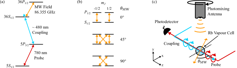
The experiments of Ref. [24] considered cesium atoms dressed in linearly polarized microwave radiation, resonant with the transition between the two Rydberg levels and . Our experiments presented in this paper make use of the and levels of , which establishes an equivalent scenario as it is the coupled angular momentum characteristics (factored out by the Wigner-Eckardt theorem) which contains the relevant physics. Figure 1(a) shows a level diagram for while Fig. 1(b) shows how the and magnetic sublevels are coupled for linearly polarized MW at angles , , and with respect to the quantization axis. We stress that the three situations are physically identical—the apparent difference simply results from a transformation between bases. This also means that when diagonalizing the coupling Hamiltonian one will get the same eigenvalues irrespective of the polarization angle. In the dipole and rotating wave approximations, the coupling is for a resonant microwave field of amplitude and polarization . Formally, performing a classical rotation of the polarization vector , we have , where is the quantum mechanical rotation operator [25]. Since this constitutes a similarity transformation has the same eigenvalues as . Specifically, for resonantly coupled and levels, the representation of in the Zeeman basis with a linearly polarized microwave field oriented along the quantization axis (which we take to be the -axis) is
| (1) |
where the ordering of basis states used to calculate the matrix elements are shown at the upper and right margins of the -matrix. For example
| (2) |
with Rabi frequency . In obtaining this, the Wigner-Eckart theorem has been used to express as a signed product of of a 3- symbol and a reduced matrix element (cf. underbraced quantity). Noting that for the reduced matrix element we have [26], the remaining three non-zero entries of Eq. (1) follow in a similar fashion. The coupling Hamiltonian in Eq. (1) has two eigenvalues .
Upon rotating the microwave polarization by an angle about the -axis, the Hamiltonian for the coupled system becomes
| (3) |
where, for example
Equation (3) differs to equation B1 of [24], by (at least) a sign in two entries. This explains why Ref. [24] reaches the conclusion that the eigenvalues change as the polarization is rotated. In contrast, and as expected from symmetry, of Eq. (3) displays the same two eigenvalues as H in Eq. (1), namely .
To experimentally investigate the polarization dependence for an transition probed using EIT, we perform spectroscopy via the ladder scheme of Fig. 1(a) with the experimental configuration shown in Fig. 1(c). Here, a probe laser is locked to the transition in , while a coupling laser is tuned to the transition, establishing an EIT condition for the probe beam by the atomic medium. The coupling laser is scanned, and the EIT transmission is recorded as a function of the coupling laser detuning from the resonance. The dashed line in Fig. 2 shows a single transmission peak, centered on zero detuning. The probe and coupling beams have Rabi frequencies of and , respectively, and diameters of and . We modulate the amplitude of the coupling beam at using an optical chopper, enabling the use of lock-in detection. The probe and coupling beams counter-propagate along the -axis to suppress effects of Doppler broadening and are circularly polarized. Figure 2 shows the effect on the EIT spectrum of applying a linearly polarized MW field tuned to the transition at and propagating along the -axis 111Our experimental implementation uses a microwave field produced by a commercially available terahertz source (Toptica TeraBeam 1550), with the emitter mounted in a motorized rotation stage positioned above the cell and is [cf. Fig. 1(c)].. Virtually identical AT splittings are found for the polarization angles —corresponding to the situations of Fig. 1(b). This invariance extend to the entire angular range of .
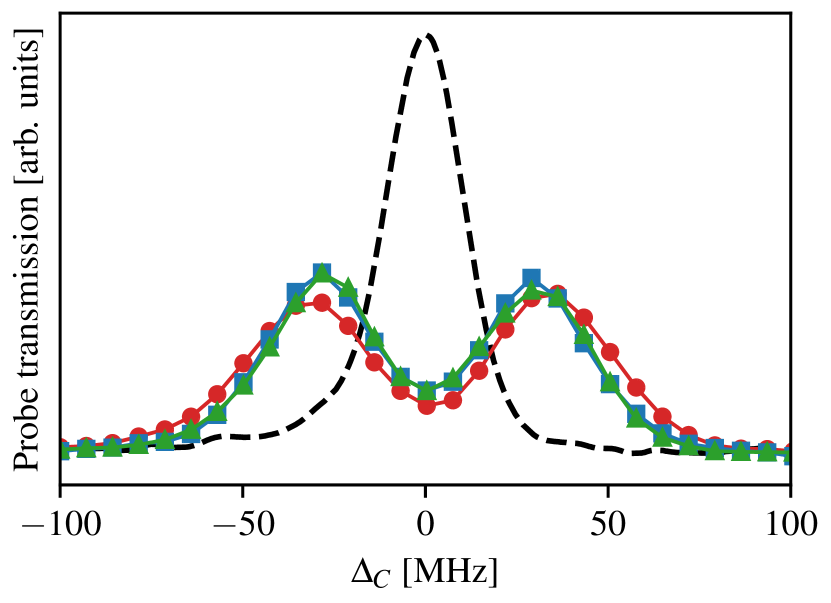
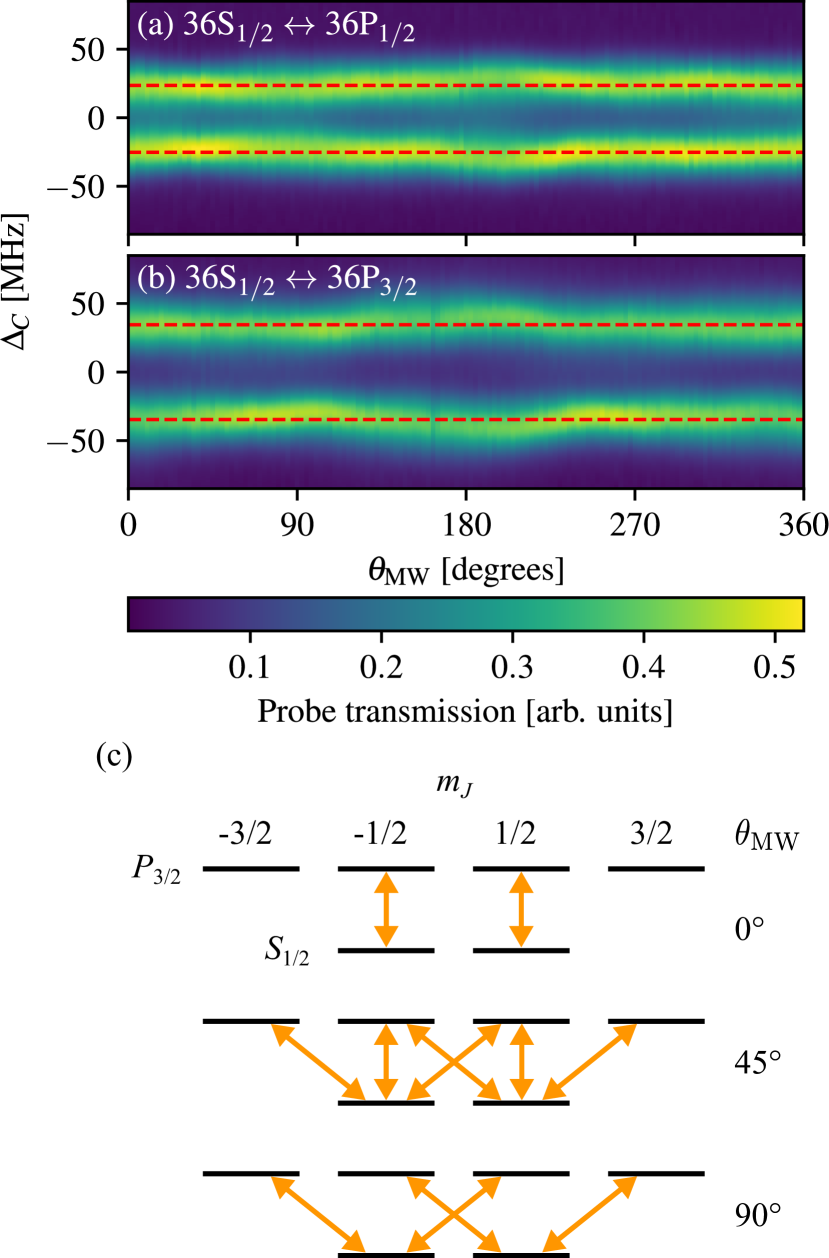
Figure 3(a) maps the AT splitting as is rotated. EIT spectra are recorded every , all showing two peaks. The peak positions remain constant within MHz from their angular averages, overlaid on Fig. 3(a) as two red dashed lines split by . For a resonant MW field, this frequency splitting is related to the MW Rabi frequency by [4]
| (5) |
where is the transition dipole moment between states and , and is the electric field amplitude. We attribute the small variation in the observed AT splitting to the MW field distribution not being cylindrically symmetric about the axis of rotation [28, 29].
So far we have investigated a linear MW field dressing a system and established that this gives rise to two eigenenergies for the coupling Hamitonian and in turn two peaks in the EIT spectrum. In general, the number of unique eigenenergies for a coupled system (subject to dipole transition selection rules) can be shown to be
| (6) |
For , the number of peaks in the EIT spectrum equals , as for the case considered above. For , the number of peaks will depend on which of the two the EIT coupling laser connects to. If the last optical rung on the EIT ladder corresponds to the larger of and the peak number equals . However, if the coupling laser light connects to the level with the lower of the two, the number of peaks will be . Hence if for the topmost level of the ladder Fig. 1(a) we make use of rather than , we would still expect only two peaks in the EIT spectrum despite the coupling matrix having three eigenvalues. Indeed, Fig. 3(b) presents results from experimental measurements with the microwave field tuned in resonance with the transition at , revealing two peaks split by . This splitting is larger than for the transition and since the difference in transition dipole moments for the two is only this must be the direct result of a change in MW power at the atoms’ location [cf. Eq. (5)]. We ascribe the frequency dependence of the emitted power from the THz source. As such, the polarization-insensitivity of the transitions of Fig. 3(a,b) figure makes this experimental scheme a promising candidate for measuring emitter properties.
Figure 3(c) shows how the and magnetic sublevels are coupled for linearly polarized MW at angles , , and with respect to the quantization axis. For the case it is straightforward to see that the system will have three eigenenergies, as it is represented by two independent, identical, coupled two-level systems in addition to two uncoupled energy-degenerate states, coined spectator states [30]. With the coupling laser connecting to the level it is clear that the spectator states will have no influence on the EIT spectrum. For the representations of the and cases, which both contain linkages between states, the number of eigenenergies is not obvious from inspection of the diagrams in Fig. 3(c). The Morris-Shore transformation [30] provides the Hilbert space coordinate transforms that will turn the linked systems into the unlinked one. While this method lends itself to more general polarization states [31], for the purely linearly polarized radiation considered in the present work this is simply achieved by picking a quantization axis coaxially with the polarization.
While the eigenenergies found when coupling two Rydberg levels with lineraly polarized MW are universally insensitive to the polarization angle as discussed above, the invariance of the EIT signals with angle in Fig. 3(a,b) are special cases of the coupling light connecting to a level and the associated symmetry. Stationary eigenenergies are a necessary but not sufficient condition for the invariance and in general the EIT signal can carry an imprint of the polarization angle as demonstrated in [18] for a ladder. In a future publication we will contrast a -ladder to a -ladder. These two scenarios carry distinctly different EIT signatures and may form the basis of a differential polarimetry scheme for MW and THz radiation. Meanwhile, Rydberg transitions, that were the focus of the present paper, can, as we have demonstrated, not be used for polarimetry. Rather, such transitions should be sought in applications, where insensitivity to polarization effects are desired.
Acknowledgments.—This work was supported by the Marsden Fund of New Zealand (Contracts Nos. UOO1923 and UOO1729) and by MBIE (Contract No. UOOX1915). NK acknowledges the hospitality of Aarhus University during the write-up of the manuscript.
References
- Jing et al. [2020] M. Jing, Y. Hu, J. Ma, H. Zhang, L. Zhang, L. Xiao, and S. Jia, Atomic superheterodyne receiver based on microwave-dressed Rydberg spectroscopy, Nat. Phys. 16, 911 (2020).
- Prajapati et al. [2021] N. Prajapati, A. K. Robinson, S. Berweger, M. T. Simons, A. B. Artusio-Glimpse, and C. L. Holloway, Enhancement of electromagnetically induced transparency based Rydberg-atom electrometry through population repumping, Appl. Phys. Lett. 119, 214001 (2021).
- Hu et al. [2022] J. Hu, H. Li, R. Song, J. Bai, Y. Jiao, J. Zhao, and S. Jia, Continuously tunable radio frequency electrometry with Rydberg atoms, Appl. Phys. Lett. 121, 014002 (2022).
- Sedlacek et al. [2012] J. Sedlacek, A. Schwettmann, H. Kübler, R. Löw, T. Pfau, and J. Shaffer, Microwave electrometry with Rydberg atoms in a vapour cell using bright atomic resonances, Nat. Phys. 8, 819 (2012).
- Holloway et al. [2014] C. L. Holloway, J. A. Gordon, S. Jefferts, A. Schwarzkopf, D. A. Anderson, S. A. Miller, N. Thaicharoen, and G. Raithel, Broadband Rydberg atom-based electric-field probe for SI-traceable, self-calibrated measurements, IEEE Trans. Antennas Propag. 62, 6169 (2014).
- Anderson et al. [2021] D. A. Anderson, R. E. Sapiro, and G. Raithel, A self-calibrated SI-traceable Rydberg atom-based radio frequency electric field probe and measurement instrument, IEEE Trans. Antennas Propag. 69, 5931 (2021).
- Holloway et al. [2017a] C. L. Holloway, M. T. Simons, J. A. Gordon, P. F. Wilson, C. M. Cooke, D. A. Anderson, and G. Raithel, Atom-based RF electric field metrology: From self-calibrated measurements to subwavelength and near-field imaging, IEEE Trans. Electromagn. Compat. 59, 717 (2017a).
- Holloway et al. [2017b] C. L. Holloway, M. T. Simons, J. A. Gordon, P. F. Wilson, C. M. Cooke, D. A. Anderson, and G. Raithel, Atom-based RF electric field metrology: From self-calibrated measurements to subwavelength and near-field imaging, IEEE Trans. Electromagn. Compat. 59, 717 (2017b).
- Meyer et al. [2018] D. H. Meyer, K. C. Cox, F. K. Fatemi, and P. D. Kunz, Digital communication with Rydberg atoms and amplitude-modulated microwave fields, Appl. Phys. Lett. 112, 211108 (2018).
- Song et al. [2018] Z. Song, W. Zhang, X. Liu, H. Zou, J. Zhang, Z. Jiang, and J. Qu, Quantum-based amplitude modulation radio receiver using rydberg atoms, in 2018 IEEE Globecom Workshops (GC Wkshps) (2018) pp. 1–6.
- Deb and Kjærgaard [2018] A. B. Deb and N. Kjærgaard, Radio-over-fiber using an optical antenna based on Rydberg states of atoms, Appl. Phys. Lett. 112, 211106 (2018).
- Otto et al. [2023] J. S. Otto, M. Chilcott, A. B. Deb, and N. Kjærgaard, Distant RF field sensing with a passive Rydberg-atomic transducer, Appl. Phys. Lett. 123, 144003 (2023).
- Holloway et al. [2017c] C. L. Holloway, M. T. Simons, J. A. Gordon, P. F. Wilson, C. M. Cooke, D. A. Anderson, and G. Raithel, Atom-based RF electric field metrology: From self-calibrated measurements to subwavelength and near-field imaging, IEEE Trans. Electromagn. Compat. 59, 717 (2017c).
- Downes et al. [2020] L. A. Downes, A. R. MacKellar, D. J. Whiting, C. Bourgenot, C. S. Adams, and K. J. Weatherill, Full-field terahertz imaging at kilohertz frame rates using atomic vapor, Phys. Rev. X 10, 011027 (2020).
- Anderson et al. [2023] D. A. Anderson, L. F. Goncalves, R. Legaie, and G. Raithel, Towards Rydberg atom synthetic apertures: Wide-area high-resolution RF amplitude and phase imaging with Rydberg probes, in 2023 IEEE International Conference on Acoustics, Speech, and Signal Processing Workshops (ICASSPW) (2023) pp. 1–5.
- Anderson et al. [2022] D. Anderson, R. Sapiro, L. Gonçalves, R. Cardman, and G. Raithel, Optical radio-frequency phase measurement with an internal-state Rydberg atom interferometer, Phys. Rev. Appl. 17, 044020 (2022).
- Berweger et al. [2023] S. Berweger, A. B. Artusio-Glimpse, A. P. Rotunno, N. Prajapati, J. D. Christesen, K. R. Moore, M. T. Simons, and C. L. Holloway, Phase-resolved Rydberg atom field sensing using quantum interferometry (2023), arXiv:2212.00185 [physics.atom-ph] .
- Sedlacek et al. [2013] J. A. Sedlacek, A. Schwettmann, H. Kübler, and J. P. Shaffer, Atom-based vector microwave electrometry using rubidium Rydberg atoms in a vapor cell, Phys. Rev. Lett. 111, 063001 (2013).
- Jiao et al. [2017] Y. Jiao, L. Hao, X. Han, S. Bai, G. Raithel, J. Zhao, and S. Jia, Atom-based radio-frequency field calibration and polarization measurement using cesium floquet states, Phys. Rev. Appl. 8, 014028 (2017).
- Anderson et al. [2018] D. A. Anderson, E. G. Paradis, and G. Raithel, A vapor-cell atomic sensor for radio-frequency field detection using a polarization-selective field enhancement resonator, Appl. Phys. Lett. 113, 073501 (2018).
- Wang et al. [2023] Y. Wang, F. Jia, J. Hao, Y. Cui, F. Zhou, X. Liu, J. Mei, Y. Yu, Y. Liu, J. Zhang, F. Xie, and Z. Zhong, Precise measurement of microwave polarization using a Rydberg atom-based mixer, Opt. Express 31, 10449 (2023).
- Mohapatra et al. [2007] A. K. Mohapatra, T. R. Jackson, and C. S. Adams, Coherent optical detection of highly excited Rydberg states using electromagnetically induced transparency, Phys. Rev. Lett. 98, 113003 (2007).
- Simons et al. [2021] M. T. Simons, A. B. Artusio-Glimpse, A. K. Robinson, N. Prajapati, and C. L. Holloway, Rydberg atom-based sensors for radio-frequency electric field metrology, sensing, and communications, Meas.: Sens. 18, 100273 (2021).
- Chopinaud and Pritchard [2021] A. Chopinaud and J. D. Pritchard, Optimal state choice for Rydberg-atom microwave sensors, Phys. Rev. Appl. 16, 024008 (2021).
- Sakurai and Napolitano [2020] J. J. Sakurai and J. Napolitano, Modern Quantum Mechanics (Cambridge University Press, 2020).
- Auzinsh et al. [2010] M. Auzinsh, D. Budker, and S. M. Rochester, Optically Polarized Atoms (Oxford University Press, 2010).
- Note [1] Our experimental implementation uses a microwave field produced by a commercially available terahertz source (Toptica TeraBeam 1550), with the emitter mounted in a motorised rotation stage positioned above the cell and is [cf. Fig. 1(c)].
- Nellen et al. [2021] S. Nellen, S. Lauck, G. Schwanke, M. Deumer, R. B. Kohlhaas, L. Liebermeister, M. Schell, and B. Globisch, Radiation pattern of planar optoelectronic antennas for broadband continuous-wave terahertz emission, Opt. Express 29, 8244 (2021).
- Smith et al. [2021] J. Smith, M. Naftaly, S. Nellen, and B. Globisch, Beam profile characterisation of an optoelectronic silicon lens-integrated PIN-PD emitter between 100 GHz and 1 THz, Appl. Sci. 11, 465 (2021).
- Shore [2013] B. W. Shore, Two-state behavior in -state quantum systems: The Morris-Shore transformation reviewed, J. Mod. Opt. 61, 787 (2013).
- Bevilacqua and Arimondo [2022] G. Bevilacqua and E. Arimondo, Bright and dark Autler–Townes states in the atomic rydberg multilevel spectroscopy, J. Phys. B 55, 154001 (2022).