Mechanical Comparison of Arrangement Strategies for Topological Interlocking Assemblies

Tom Goertzen RWTH Aachen University, Chair of Algebra and Representation Theory, Pontdriesch 10-16, 52062 Aachen, Germany Domen Macek RWTH Aachen University, Institute of Applied Mechanics, Mies-van-der-Rohe-Str. 1, 52074 Aachen, Germany Lukas Schnelle RWTH Aachen University, Chair of Algebra and Representation Theory, Pontdriesch 10-16, 52062 Aachen, Germany Meike Weiß RWTH Aachen University, Chair of Algebra and Representation Theory, Pontdriesch 10-16, 52062 Aachen, Germany Stefanie Reese RWTH Aachen University, Institute of Applied Mechanics, Mies-van-der-Rohe-Str. 1, 52074 Aachen, Germany Hagen Holthusen RWTH Aachen University, Institute of Applied Mechanics, Mies-van-der-Rohe-Str. 1, 52074 Aachen, Germany Alice C. Niemeyer RWTH Aachen University, Chair of Algebra and Representation Theory, Pontdriesch 10-16, 52062 Aachen, Germany
Abstract

Topological Interlocking assemblies are arrangements of blocks kinematically constrained by a fixed frame, such that all rigid body motions of each block are constrained only by its permanent contact with other blocks and the frame. In the literature several blocks are introduced that can be arranged into different interlocking assemblies. In this study we investigate the influence of arrangement on the overall structural behaviour of the resulting interlocking assemblies. This is performed using the Versatile Block, as it can be arranged in three different doubly periodic ways given by wallpaper symmetries. Our focus lies on the load transfer mechanisms from the assembly onto the frame. For fast a priori evaluation of the assemblies we introduce a combinatorial model called Interlocking Flows. To investigate our assemblies from a mechanical point of view we conduct several finite element studies. These reveal a strong influence of arrangement on the structural behaviour, for instance, an impact on both the point and amount of maximum deflection. The results of the finite element analysis are in very good agreement with the predictions of the Interlocking Flow model. Our source code, data and examples are available under https://doi.org/10.5281/zenodo.10246034.

**footnotetext: These authors contributed equally to this work.

Keywords: topological interlocking, Versatile Block, FEM, wallpaper symmetries, directional blocking graphs

1 Introduction

The aim of resource efficiency and resource savings drives us to optimise not only the recyclability of everyday consumer goods but also the recyclability of components in the construction industry. Components are typically manufactured monolithically tailored to a specific application and consist of high performance composites. They require separation for recycling, which in most cases consumes additional energy. This raises the question of how to achieve resource efficiency without the need for recycling. One possible solution is to start at an earlier stage, namely to design buildings with reusable components. To achieve reusability, a transition from a monolithic approach to a modular design is required. Reusable components offer the potential of being assembled into different load-bearing structures. For example, components consisting of individual blocks that kinetically constrain each other and display structural load-bearing behaviour are particularly desirable.

The idea of building mortarless structures from blocks that kinematically constrain each other has been known for a long time (see Section 2). We are particularly interested in topological interlocking assemblies which give rise to planar mortarless structures. The structural behaviour of an interlocking assembly of tetrahedra has first been investigated in Dyskin et al. (2001a).

Mathematically, a topological interlocking assembly can be defined as an arrangement of blocks that are in contact with each other together with a frame such that, if the frame is fixed, any non-empty finite subset of blocks of the arrangement is prevented from moving. This restriction of movement is enforced by the neighbours of any block and thus captures the aim of having blocks that kinetically constrain each other. While in the well known tetrahedral interlocking assembly the individual tetrahedra can only be assembled in one way, other blocks exist that can be arranged into topological interlocking assemblies in a number of ways (see Dyskin et al. (2003b) and Akpanya et al. (2023b, Lemma 1)).

In this contribution, we investigate the influence of the arrangement on the structural behaviour of a topological interlocking assembly. Our investigations focus on a specific block, called the Versatile Block (see Section 3.2), that allows many different arrangements. Here we focus on three different symmetric assemblies that can be used as plate-like structures, called planar assemblies. The results of this paper show that these arrangements of the Versatile Block into planar topological interlocking assemblies display surprisingly different mechanical performance.

As bending loads are most relevant for plates, these are perfectly suited to understand the load transfer mechanisms of topological interlocking assemblies. To evaluate the three considered interlockings in terms of load-bearing behaviour and serviceability, we compare the equivalent stresses and deflections of the topological interlocking assemblies with the results of a monolithic plate (Section 4).

Finally, we introduce a combinatorial tool (Section 5), which we call ‘Interlocking Flows’, that allows a fast prediction of how load transfer onto a frame occurs. The pre-evaluation obtained by the combinatorial tool of the assemblies we consider is consistent with the results of the FEM analyses we conducted (Section 4).

2 Literature Review

2.1 Design Principles and Applications

The concept of topological interlocking assemblies (TIA), also known as topological interlocking materials (TIM) or topological interlocking structures (TIS), has a long history. It is related to the concept of masonry and the idea of building flat vaults. Early patents and concepts of blocks that admit a topological interlocking assembly can be found in the work of Abeille and of Truchet in Gallon (1735) as well as Frézier, who generalizes the work of Abeille and Truchet, Frézier (1738). The block proposed by Abeille can be viewed as a truncated tetrahedron. Glickman proposes a paving block related to an assembly of tetrahedra Glickman (1984). Dyskin et al. (2001a) initiate an investigation of topological interlocking assemblies as a novel material design concept and coin the term ‘topological interlocking’ in Dyskin et al. (2001b). Moreover, they show that all platonic solids give rise to topological interlocking assemblies Dyskin et al. (2003a) and describe a method for constructing TIA with convex blocks Kanel-Belov et al. (2010). Osteomorphic type blocks, which are introduced in Dyskin et al. (2003b), can also be assembled in various non-planar ways and this versatility gives rise to applications in civil engineering, see Dyskin et al. (2003b); Yong (2011); Rezaee Javan et al. (2016). Other methods for generating TIA linked to Voronoi tesselations are proposed in Subramanian et al. (2019); Akleman et al. (2020); Mullins et al. (2022). Voronoi tesselations are naturally linked to crystallographic groups as certain (convex) Voronoi cells yield fundamental domains for such groups and thus space-filling structures, for example space-filling ‘VoroNoodles’ Ebert et al. (2023).

A general method for constructing planar TIA based on non-convex fundamental domains of a crystallographic group is introduced in Goertzen et al. (2022) and for non-planar TIA in Akpanya et al. (2023a). One block, called the Versatile Block, generated by the method given in Goertzen et al. (2022) has an additional property of versatility similar to the osteomorphic block: the Versatile Block can be arranged into TIA in infinitely many ways, three of which are invariant under the symmetries of a planar crystallographic group Akpanya et al. (2023b). Recent overviews of design principles and applications related to TIA are given in Dyskin et al. (2019); Estrin et al. (2021).

2.2 Mechanical and Experimental Investigations

In this paper, the focus lies on the mechanics of certain TIA based on the Versatile Block Akpanya et al. (2023b); Goertzen et al. (2022). For this endeavour, the simulation software ABAQUS is applied. Different investigations in the literature focus on TIA made of several materials such as brittle materials (ceramics, concrete), metals (aluminium, steel) and different kinds of plastic. TIA based on ceramics are, for instance, investigated in Krause et al. (2012), where the authors compare fracture toughness between monolithic ceramic plates and assemblies of osteomorphic ceramics parts. In Mirkhalaf et al. (2018) a parameter study comparing several convex blocks based on regular square and hexagon tessellations is conducted. Several mechanical experiments and simulations studying the behaviour of TIA with osteomorphic type concrete blocks are conducted in Rezaee Javan et al. (2017); Rezaee Javan et al. (2018); Rezaee Javan et al. (2020). Isotropic linear–elastic materials such as aluminium and steel are investigated in Dugué et al. (2013) using finite element and discrete element methods. In Schaare et al. (2008, 2009) TIA based on aluminium and steel cubes are experimentally and numerically studied. Mechanical properties of parameterised TIA based on ‘VoroNoodles’ are analysed in Ebert et al. (2023). Mechanical properties of TIA made with plastics such as Acrylonitrile butadiene styrene (ABS) are investigated in several works. In Weizmann et al. (2021) assemblies of convex ABS blocks are generated and compared based on a parameter study with angles and different tessellations. Impact mechanics of TIA with tetrahedra are studied in Feng et al. (2015). Various parametric studies based on scaling and convex blocks coming from various tessellations are conducted in Short and Siegmund (2019); Kim and Siegmund (2021); Williams and Siegmund (2021). Investigations on effects of Young’s modulus and the friction coefficient on the structural mechanics of TIA are investigated in Koureas et al. (2022); Feldfogel et al. (2023, 2024). In Koureas et al. (2023) the effect of non-planar block geometry in the context of beam-like structures is studied. In Ullmann et al. (2023) a comparative study on the deflection limit of slab-like assemblies monolithic slabs is conducted.

3 Symmetric topological interlocking assemblies

3.1 Topological Interlocking

A topological interlocking assembly (TIA) can be defined as an arrangement of blocks that are in contact with each other together with a frame such that, if the frame is fixed, any non-empty finite subset of blocks of the arrangement is prevented from moving. We focus on planar topological interlocking assemblies, in which blocks are arranged between two parallel planes in 3D-space. In this scenario the frame can consist of the blocks on the perimeter. In this paper we consider topological interlocking assemblies constructed from copies of the same block and investigate the question what effect the arrangement of these blocks has on the load bearing behaviour of the entire assembly. Even with the restriction of only using copies of the same block a large number of planar topological interlocking assemblies can exist (possibly exponentially many, see (Akpanya et al., 2023b, Lemma 1)). In this paper, we consider the even more restrictive case of interlocking assemblies displaying a wallpaper symmetry, more in Section 3.4.

3.2 The Versatile Block
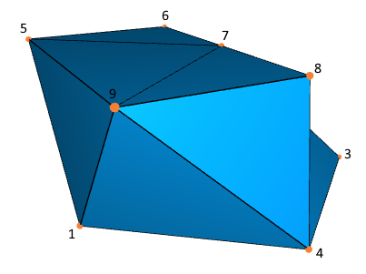
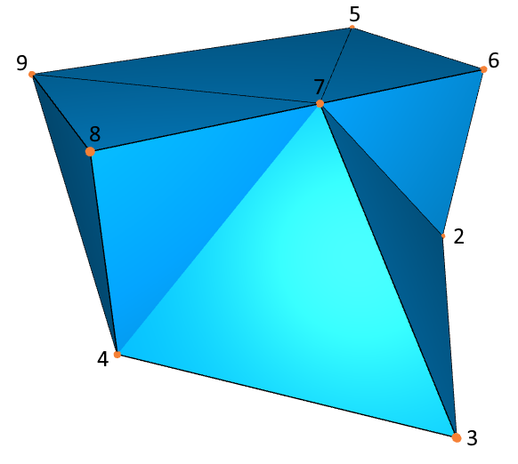
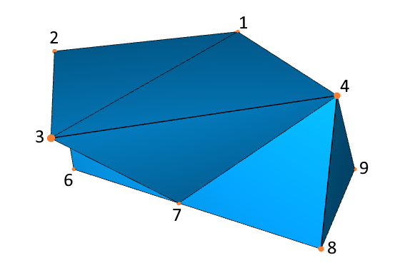
Refer to caption
Refer to caption
Refer to caption
Figure 1: Three views of the Versatile Block

The Versatile Block, called B𝐵B, is a polyhedron embedded in 3superscript3\mathbb{R}^{3}. It consists of vertices, called B0subscript𝐵0B_{0}, edges, called B1subscript𝐵1B_{1}, and triangular faces, called B2subscript𝐵2B_{2}, and was first defined in Goertzen et al. (2022). More precisely, B𝐵B has 999 vertices, 212121 edges and 141414 faces. Let B0={v1,,v9}subscript𝐵0subscript𝑣1subscript𝑣9B_{0}=\{v_{1},\ldots,v_{9}\,\} denote the vertices of B𝐵B. Then the edges B1subscript𝐵1B_{1} are the following 2-subsets of vertices:

B1:={\displaystyle B_{1}:=\{\, {v1,v2},{v1,v3},{v1,v4},{v1,v5},{v1,v9},{v2,v3},{v2,v5},subscript𝑣1subscript𝑣2subscript𝑣1subscript𝑣3subscript𝑣1subscript𝑣4subscript𝑣1subscript𝑣5subscript𝑣1subscript𝑣9subscript𝑣2subscript𝑣3subscript𝑣2subscript𝑣5\displaystyle\{v_{1},v_{2}\},\,\{v_{1},v_{3}\},\,\{v_{1},v_{4}\},\,\{v_{1},v_{5}\},\,\{v_{1},v_{9}\},\,\{v_{2},v_{3}\},\,\{v_{2},v_{5}\},
{v2,v6},{v2,v7},{v3,v4},{v3,v7},{v4,v7},{v4,v8},{v4,v9},subscript𝑣2subscript𝑣6subscript𝑣2subscript𝑣7subscript𝑣3subscript𝑣4subscript𝑣3subscript𝑣7subscript𝑣4subscript𝑣7subscript𝑣4subscript𝑣8subscript𝑣4subscript𝑣9\displaystyle\{v_{2},v_{6}\},\,\{v_{2},v_{7}\},\,\{v_{3},v_{4}\},\,\{v_{3},v_{7}\},\,\{v_{4},v_{7}\},\,\{v_{4},v_{8}\},\,\{v_{4},v_{9}\},
{v5,v6},{v5,v7},{v5,v9},{v6,v7},{v7,v8},{v7,v9},{v8,v9}}\displaystyle\{v_{5},v_{6}\},\,\{v_{5},v_{7}\},\,\{v_{5},v_{9}\},\,\{v_{6},v_{7}\},\,\{v_{7},v_{8}\},\,\{v_{7},v_{9}\},\,\{v_{8},v_{9}\}\,\}

and the triangular faces B2subscript𝐵2B_{2} are uniquely described by the following 333-subsets of vertices:

B2:={\displaystyle B_{2}:=\{\, {v1,v2,v3},{v1,v2,v5},{v1,v3,v4},{v1,v4,v9},{v1,v5,v9},{v2,v3,v7},{v2,v5,v6},subscript𝑣1subscript𝑣2subscript𝑣3subscript𝑣1subscript𝑣2subscript𝑣5subscript𝑣1subscript𝑣3subscript𝑣4subscript𝑣1subscript𝑣4subscript𝑣9subscript𝑣1subscript𝑣5subscript𝑣9subscript𝑣2subscript𝑣3subscript𝑣7subscript𝑣2subscript𝑣5subscript𝑣6\displaystyle\{v_{1},v_{2},v_{3}\},\,\{v_{1},v_{2},v_{5}\},\,\{v_{1},v_{3},v_{4}\},\,\{v_{1},v_{4},v_{9}\},\,\{v_{1},v_{5},v_{9}\},\,\{v_{2},v_{3},v_{7}\},\,\{v_{2},v_{5},v_{6}\},
{v2,v6,v7},{v3,v4,v7},{v4,v7,v8},{v4,v8,v9},{v5,v6,v7},{v5,v7,v9},{v7,v8,v9}}.\displaystyle\{v_{2},v_{6},v_{7}\},\,\{v_{3},v_{4},v_{7}\},\,\{v_{4},v_{7},v_{8}\},\,\{v_{4},v_{8},v_{9}\},\,\{v_{5},v_{6},v_{7}\},\,\{v_{5},v_{7},v_{9}\},\,\{v_{7},v_{8},v_{9}\}\,\}.

The embedding of the Versatile Block into 3superscript3\mathbb{R}^{3} has the following coordinates, see Akpanya et al. (2023b):

v1=(0,0,0),v2=(1,1,0),v3=(2,0,0),v4=(1,1,0),formulae-sequencesubscript𝑣1000formulae-sequencesubscript𝑣2110formulae-sequencesubscript𝑣3200subscript𝑣4110\displaystyle v_{1}=(0,0,0),\,v_{2}=(1,1,0),\,v_{3}=(2,0,0),\,v_{4}=(1,-1,0),
v5=(0,1,1),v6=(1,1,1),v7=(1,0,1),v8=(1,1,1),v9=(0,1,1).formulae-sequencesubscript𝑣5011formulae-sequencesubscript𝑣6111formulae-sequencesubscript𝑣7101formulae-sequencesubscript𝑣8111subscript𝑣9011\displaystyle v_{5}=(0,1,1),\,v_{6}=(1,1,1),\,v_{7}=(1,0,1),\,v_{8}=(1,-1,1),\,v_{9}=(0,-1,1).

The pair {{v1,v2,v3},{v1,v3,v4}}subscript𝑣1subscript𝑣2subscript𝑣3subscript𝑣1subscript𝑣3subscript𝑣4\{\,\{v_{1},v_{2},v_{3}\},\,\{v_{1},v_{3},v_{4}\}\,\} of faces forms a square in the plane z=0𝑧0z=0 with area 2, whereas the set {{v5,v6,v7},{v5,v7,v9},{v7,v8,v9}}subscript𝑣5subscript𝑣6subscript𝑣7subscript𝑣5subscript𝑣7subscript𝑣9subscript𝑣7subscript𝑣8subscript𝑣9\{\,\{v_{5},v_{6},v_{7}\},\,\{v_{5},v_{7},v_{9}\},\,\{v_{7},v_{8},v_{9}\}\,\} of faces forms a rectangle in the plane z=1𝑧1z=1 of the same area. In fact, the intersection of B𝐵B with any plane z=a𝑧𝑎z=a with a[0,1]𝑎01a\in[0,1] yields a polygon with area 222. We call the plane z=0𝑧0z=0 the bottom plane and the plane z=1𝑧1z=1 the top plane. Note that all vertices of the Versatile Block lie in either the top or bottom plane.

The Versatile Block can be used to create many different planar assemblies sandwiched between the bottom and top plane, such that each block is placed in such a way, that the square is in the bottom plane and the rectangle is in the top plane, see (Akpanya et al., 2023b, Lemma 1). In this paper we are interested in planar topological interlocking assemblies of copies of the Versatile Block, that remain unchanged under certain rotations, reflections and translations. For this we need to introduce a formal way to describe these symmetries.

3.3 Wallpaper groups

Wallpaper groups can be seen as a mathematical formulation of symmetries of certain doubly periodic repeating patterns in a 222-dimensional plane. They are also known as 222-dimensional crystallographic groups and contain rotations, reflections and translations respecting the repeated pattern. For the repetition of the pattern we need a translation which describes the offset of the pattern, denoted as a vector in 2superscript2\mathbb{R}^{2}. Furthermore, a rotation or reflection can be described by a matrix

(cos(θ)sin(θ)sin(θ)cos(θ)) or (cos(θ)sin(θ)sin(θ)cos(θ))matrix𝑐𝑜𝑠𝜃𝑠𝑖𝑛𝜃𝑠𝑖𝑛𝜃𝑐𝑜𝑠𝜃 or matrix𝑐𝑜𝑠𝜃𝑠𝑖𝑛𝜃𝑠𝑖𝑛𝜃𝑐𝑜𝑠𝜃\begin{pmatrix}cos(\theta)&-sin(\theta)\\ sin(\theta)&cos(\theta)\end{pmatrix}\text{ or }\begin{pmatrix}cos(\theta)&sin(\theta)\\ sin(\theta)&-cos(\theta)\end{pmatrix}

respectively, where θ𝜃\theta is the angle. A reflection means, we mirror at a plane through the origin with a certain angle. It turns out, that θ𝜃\theta can only have the values 0,60,90,120,superscript0superscript60superscript90superscript1200^{\circ},60^{\circ},90^{\circ},120^{\circ}, and 180superscript180180^{\circ} (see crystallographic restriction theorem (Armstrong, 1988, Chapter 25)). A single symmetry of a repeating pattern can therefore be described as pair (M,v)𝑀𝑣(M,v) where M𝑀M is a rotation or reflection matrix and v𝑣v is an (offset) vector as before. We call such an object an isometry. An isometry (M,v)𝑀𝑣(M,v) acts on 2superscript2\mathbb{R}^{2} as the function

f(M,v):22,x=(x1x2)M(x1x2)+v,:subscript𝑓𝑀𝑣formulae-sequencesuperscript2superscript2𝑥matrixsubscript𝑥1subscript𝑥2maps-to𝑀matrixsubscript𝑥1subscript𝑥2𝑣f_{(M,v)}:\mathbb{R}^{2}\to\mathbb{R}^{2},x=\begin{pmatrix}x_{1}\\ x_{2}\end{pmatrix}\mapsto M\cdot\begin{pmatrix}x_{1}\\ x_{2}\end{pmatrix}+v,

whereas the product of two isometries (M1,v1),(M2,v2)subscript𝑀1subscript𝑣1subscript𝑀2subscript𝑣2(M_{1},v_{1}),(M_{2},v_{2}) is defined as follows:

(M2,v2)(M1,v1)(M2M1,M2v1+v2)subscript𝑀2subscript𝑣2subscript𝑀1subscript𝑣1subscript𝑀2subscript𝑀1subscript𝑀2subscript𝑣1subscript𝑣2(M_{2},v_{2})\circ(M_{1},v_{1})\coloneqq(M_{2}\cdot M_{1},M_{2}\cdot v_{1}+v_{2})

with \cdot the matrix-vector multiplication. Every wallpaper group is generated by a finite set of isometries, see (Szczepański, 2012, Def 2.1). That means elements of the group are products of these isometries. To be more precise we define a wallpaper group along the same lines as (Armstrong, 1988, Chapter 25) as follows:

Definition 3.1.

Let E(2)E2\mathrm{E}(2) denote the group of isometries of the Euclidean plane 2superscript2\mathbb{R}^{2}. A subgroup

Γ(M1,v1),,(Mr,vr)E(2)Γsubscript𝑀1subscript𝑣1subscript𝑀𝑟subscript𝑣𝑟E2\Gamma\coloneqq\langle\,(M_{1},v_{1}),\dots,(M_{r},v_{r})\,\rangle\subseteq\mathrm{E}(2)

such that Misubscript𝑀𝑖M_{i} is a rotation or reflection matrix and vi2subscript𝑣𝑖superscript2v_{i}\in\mathbb{R}^{2} for 1ir1𝑖𝑟1\leq i\leq r is called wallpaper group if

  1. (i)

    the set {v1,,vr}subscript𝑣1subscript𝑣𝑟\{v_{1},\dots,v_{r}\} contains two linearly independents vectors and

  2. (ii)

    there are only finitely many matrices that can be written as M=Mi1Mik𝑀subscript𝑀subscript𝑖1subscript𝑀subscript𝑖𝑘M=M_{i_{1}}\cdot\dots\cdot M_{i_{k}} with Mij{M1,,Mr}subscript𝑀subscript𝑖𝑗subscript𝑀1subscript𝑀𝑟M_{i_{j}}\in\{M_{1},\dots,M_{r}\}, 1jk1𝑗𝑘1\leq j\leq k (i.e. the Misubscript𝑀𝑖M_{i} span a finite point group).

In this definition, (i)𝑖(i) ensures that we can find a smallest area D2𝐷superscript2D\subseteq\mathbb{R}^{2} (called fundamental domain) such that for any point x𝑥x in the plane there is a point yP𝑦𝑃y\in P and an isometry in ΓΓ\Gamma that maps x𝑥x to y𝑦y. (ii)𝑖𝑖(ii) ensures that we obtain a repeating pattern, which was our goal. It turns out, that with this definition it can be shown that there are only 171717 wallpaper groups (up to isomorphism), see (Armstrong, 1988, Chapter 26).

In this paper we only consider the following three wallpaper groups:

p1((1001),(11)),((1001),(11)).𝑝1matrix1001matrix11matrix1001matrix11p1\coloneqq\left<\left(\begin{pmatrix}1&0\\ 0&1\end{pmatrix},\begin{pmatrix}1\\ -1\end{pmatrix}\right),\left(\begin{pmatrix}1&0\\ 0&1\end{pmatrix},\begin{pmatrix}1\\ 1\end{pmatrix}\right)\right>.

The group p1𝑝1p1 can be characterised by only allowing translations as both matrices are the identity.
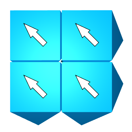
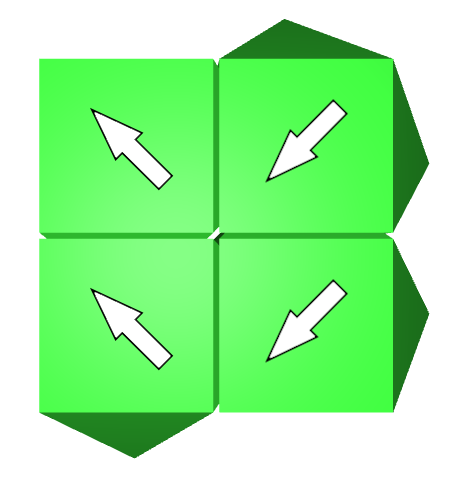
pg((0110),(20)),((1001),(11)).𝑝𝑔matrix0110matrix20matrix1001matrix11pg\coloneqq\left<\left(\begin{pmatrix}0&-1\\ -1&0\end{pmatrix},\begin{pmatrix}2\\ 0\end{pmatrix}\right),\left(\begin{pmatrix}1&0\\ 0&1\end{pmatrix},\begin{pmatrix}1\\ 1\end{pmatrix}\right)\right>.

In the group pg𝑝𝑔pg we gain a (glide-)reflection in the first generator. After applying this matrix twice it becomes the identity and therefore the fundamental domain D𝐷D can be oriented in two ways.

p4((0110),(02)),((0110),(02)),((1001),(00))𝑝4matrix0110matrix02matrix0110matrix02matrix1001matrix00p4\coloneqq\left<\left(\begin{pmatrix}0&1\\ -1&0\end{pmatrix},\begin{pmatrix}0\\ 2\end{pmatrix}\right),\left(\begin{pmatrix}0&-1\\ 1&0\end{pmatrix},\begin{pmatrix}0\\ -2\end{pmatrix}\right),\left(\begin{pmatrix}-1&0\\ 0&-1\end{pmatrix},\begin{pmatrix}0\\ 0\end{pmatrix}\right)\right>

Compared to the one reflection in pg𝑝𝑔pg we have a rotation associated to both generators in the group p4𝑝4p4. However, due to the rotation matrices becoming the identity after being applied four times the fundamental domain D𝐷D can be oriented in exactly four ways.

Here, we follow the international crystallographic notation Aroyo (December 2016) for the names of the wallpaper groups.

3.4 Planar Assemblies of the Versatile Block

Refer to caption
(a) p1𝑝1p1
Refer to caption
(b) pg𝑝𝑔pg
Refer to caption
(c) p4𝑝4p4
Figure 2: Planar interlocking assemblies of size 9×9999\times 9 with a gap of 0.10.10.1 between blocks, generated by a their respective wallpaper group
Refer to caption
(a) p1𝑝1p1
Refer to caption
(b) pg𝑝𝑔pg
Refer to caption
(c) p4𝑝4p4
Figure 3: View of the bottom-plane with arrows towards vertex 333 to indicate the orientation
Refer to caption
(a) p1𝑝1p1
Refer to caption
(b) pg𝑝𝑔pg
Refer to caption
(c) p4𝑝4p4
Figure 4: View of the top-plane with arrows towards vertex 333 to indicate the orientation

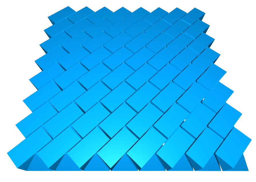
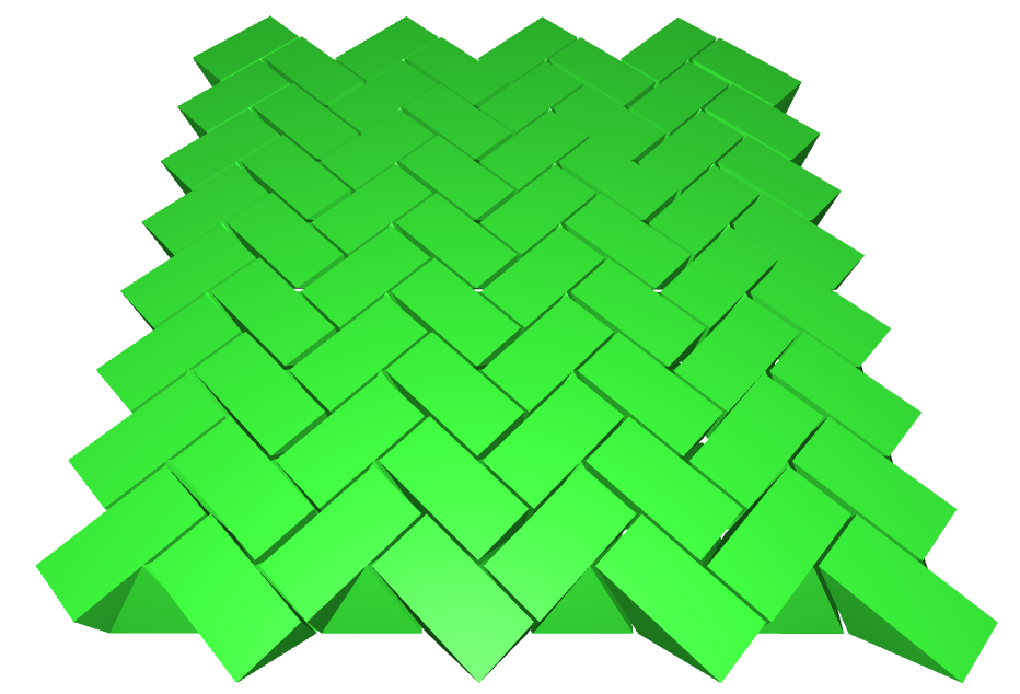
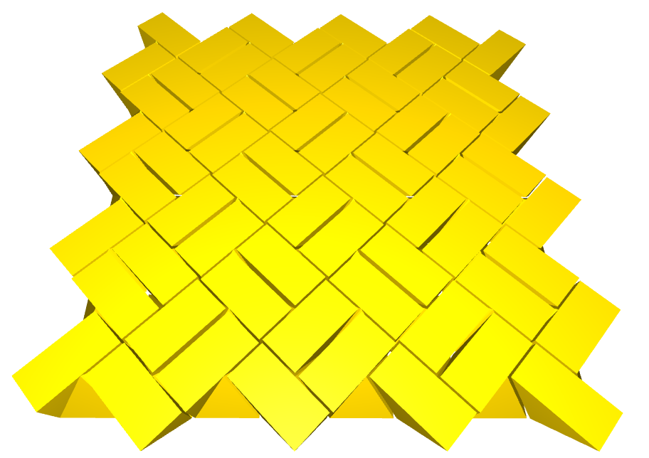
The Versatile Block is constructed in a way such that we obtain infinite planar topological interlocking assemblies with wallpaper symmetries p1𝑝1p1, pg𝑝𝑔pg or p4𝑝4p4 if the blocks are assembled in the following way:
In the bottom plane we consider the region P𝑃P as the square of the Versatile Block. We can apply an isometry on the square in the bottom plane, and keep the coordinates of the rectangle relative to the ones of the square, i.e. the isometry acts on the first two coordinates the usual way and does not change the last coordinate. Formally, this means that we extend an isometry of the Euclidean plane 2superscript2\mathbb{R}^{2} to Euclidean three-space 3superscript3\mathbb{R}^{3} for a given tuples (M,v)𝑀𝑣(M,v) to a map

f^(M,v):33,x=(x1x2x3)(M(x1x2)+vx3).:subscript^𝑓𝑀𝑣formulae-sequencesuperscript3superscript3𝑥matrixsubscript𝑥1subscript𝑥2subscript𝑥3maps-tomatrix𝑀matrixsubscript𝑥1subscript𝑥2𝑣subscript𝑥3\hat{f}_{(M,v)}:\mathbb{R}^{3}\to\mathbb{R}^{3},x=\begin{pmatrix}x_{1}\\ x_{2}\\ x_{3}\end{pmatrix}\mapsto\begin{pmatrix}M\cdot\begin{pmatrix}x_{1}\\ x_{2}\end{pmatrix}+v\\ x_{3}\end{pmatrix}.

Notice, that an isometry always keeps distances of any two vectors the same. Thus, after applying a non-trivial isometry the result is a Versatile Block rotated and translated as a whole without changing its shape and size, more in Goertzen et al. (2022) and Akpanya et al. (2023b). The three planar interlocking assemblies generated by the wallpaper groups p1𝑝1p1, pg𝑝𝑔pg, and p4𝑝4p4 are shown in Figure 2.

4 Mechanical investigation of interlocking assemblies

Our primary goal is to utilise numerical simulations to predict and characterise the mechanical behaviour of topological interlocking assemblies. By doing so, we aim to gain valuable insights into the intricate mechanisms of topological interlocking assemblies. Specifically, our focus lies in understanding the dynamic interaction between the blocks within a planar assembly when subjected to transverse loading. We examine how external forces are transferred to the frame that holds the assembly together. To further improve our understanding of the topological interlocking assembly from a mechanical point of view, we conduct a comparative analysis of the bear-loading behaviour between the assemblies and monolithic plates of the same geometry, specifically evaluating the maximum deflection and distribution of stresses.

4.1 Problem formulation

Mechanically a topological interlocking assembly consists of a set of independent bodies, which are arranged in the space and held together by the fixed, undeformable frame. In our case, the bodies are the Versatile Block. The bodies are not tied together and are considered to be deformable solids. Only the external forces (no displacements) are prescribed to the bodies in the assembly. The Versatile Blocks interact with each other only by the contact, which is unknown a priori and can change over time. The analysis does not consider friction between the blocks, allowing for a pure interlocking effect. Both the contact forces and displacements on the contact boundary of each block are not prescribed. Thus, the geometry of the blocks “constrains” the relative motion between them. Contact interaction can be mathematically interpreted as a set of nonlinear boundary conditions (see Laursen (2002) and Wriggers (2006)).

The reference configuration Ω0(k)3superscriptsubscriptΩ0𝑘superscript3\Omega_{0}^{(k)}\subset\mathbb{R}^{3} of a body k𝑘k denotes the domain occupied by all material points 𝐗(k)superscript𝐗𝑘\mathbf{X}^{(k)} at time t=0𝑡0t=0. The changed positions 𝐱(k)superscript𝐱𝑘\mathbf{x}^{(k)} of a material point at a certain time t𝑡t are described by the current configuration Ωt(k)3superscriptsubscriptΩ𝑡𝑘superscript3\Omega_{t}^{(k)}\subset\mathbb{R}^{3}. The displacement of a material point is described by 𝐮(k)(𝐗(k),t)=𝐱(k)(𝐗(k),t)𝐗(k)superscript𝐮𝑘superscript𝐗𝑘𝑡superscript𝐱𝑘superscript𝐗𝑘𝑡superscript𝐗𝑘\mathbf{u}^{(k)}(\mathbf{X}^{(k)},t)=\mathbf{x}^{(k)}(\mathbf{X}^{(k)},t)-\mathbf{X}^{(k)}. The boundary of each body Ω0(k)superscriptsubscriptΩ0𝑘\partial\Omega_{0}^{(k)} is decomposed into three sets: Γσ(k)superscriptsubscriptΓ𝜎𝑘\Gamma_{\sigma}^{(k)} representing the Neumann boundary (tractions 𝐭¯0(k)superscriptsubscript¯𝐭0𝑘\bar{\mathbf{t}}_{0}^{(k)} are given), Γu(k)superscriptsubscriptΓ𝑢𝑘\Gamma_{u}^{(k)} representing the Dirichlet boundary (displacements 𝐮¯(k)superscript¯𝐮𝑘\bar{\mathbf{u}}^{(k)} are given), and Γc(k)superscriptsubscriptΓ𝑐𝑘\Gamma_{c}^{(k)} representing the contact surface. The initial boundary value problem (strong formulation) of finite deformation elastodynamics needs to be satisfied on each body:

Div𝐏(k)+𝐛~0(k)=ρ0(k)𝐮¨(k)Divsuperscript𝐏𝑘superscriptsubscript~𝐛0𝑘superscriptsubscript𝜌0𝑘superscript¨𝐮𝑘\displaystyle\operatorname{Div}\mathbf{P}^{(k)}+\tilde{\mathbf{b}}_{0}^{(k)}=\rho_{0}^{(k)}\ddot{\mathbf{u}}^{(k)}\qquad in Ω0(k)×[0,t],in superscriptsubscriptΩ0𝑘0𝑡\displaystyle\text{in }\Omega_{0}^{(k)}\times[0,t], (1)
𝐮(k)=𝐮~(k)superscript𝐮𝑘superscript~𝐮𝑘\displaystyle\mathbf{u}^{(k)}=\tilde{\mathbf{u}}^{(k)}\qquad on Γu(k)×[0,t],on superscriptsubscriptΓ𝑢𝑘0𝑡\displaystyle\text{on }\Gamma_{u}^{(k)}\times[0,t], (2)
𝐏(k)𝐍(k)=𝐭~0(k)superscript𝐏𝑘superscript𝐍𝑘superscriptsubscript~𝐭0𝑘\displaystyle\mathbf{P}^{(k)}\mathbf{N}^{(k)}=\tilde{\mathbf{t}}_{0}^{(k)}\qquad on Γσ(k)×[0,t],on superscriptsubscriptΓ𝜎𝑘0𝑡\displaystyle\text{on }\Gamma_{\sigma}^{(k)}\times[0,t], (3)
𝐮(k)(𝐗(k),0)=𝐮~(k)(𝐗(k))superscript𝐮𝑘superscript𝐗𝑘0superscript~𝐮𝑘superscript𝐗𝑘\displaystyle\mathbf{u}^{(k)}(\mathbf{X}^{(k)},0)=\tilde{\mathbf{u}}^{(k)}(\mathbf{X}^{(k)})\qquad in Ω0(k),in superscriptsubscriptΩ0𝑘\displaystyle\text{in }\Omega_{0}^{(k)}, (4)
𝐮˙(k)(𝐗(k),0)=𝐮~˙(k)(𝐗(k))superscript˙𝐮𝑘superscript𝐗𝑘0superscript˙~𝐮𝑘superscript𝐗𝑘\displaystyle\dot{\mathbf{u}}^{(k)}(\mathbf{X}^{(k)},0)=\dot{\tilde{\mathbf{u}}}^{(k)}(\mathbf{X}^{(k)})\qquad in Ω0(k),in superscriptsubscriptΩ0𝑘\displaystyle\text{in }\Omega_{0}^{(k)}, (5)
gn(k)(𝐗(k),t)0,pn(k)(𝐗(k),t)0,pn(k)(𝐗(k),t)gn(k)(𝐗(k),t)=0formulae-sequencesuperscriptsubscript𝑔𝑛𝑘superscript𝐗𝑘𝑡0formulae-sequencesuperscriptsubscript𝑝𝑛𝑘superscript𝐗𝑘𝑡0superscriptsubscript𝑝𝑛𝑘superscript𝐗𝑘𝑡superscriptsubscript𝑔𝑛𝑘superscript𝐗𝑘𝑡0\displaystyle g_{n}^{(k)}(\mathbf{X}^{(k)},t)\geq 0,\quad p_{n}^{(k)}(\mathbf{X}^{(k)},t)\leq 0,\quad p_{n}^{(k)}(\mathbf{X}^{(k)},t)g_{n}^{(k)}(\mathbf{X}^{(k)},t)=0\qquad on Γc(k)×[0,t],on superscriptsubscriptΓ𝑐𝑘0𝑡\displaystyle\text{on }\Gamma_{c}^{(k)}\times[0,t], (6)

where 𝐏𝐏\mathbf{P} is the first Piola-Kirchhoff stress tensor, Div()Div\operatorname{Div}() denotes the Lagrangian divergence, and 𝐍𝐍\mathbf{N} is the normalised unit surface normal. The contact constraints in normal direction (6) for frictionless contact must hold on the contact boundary Γc(k)superscriptsubscriptΓ𝑐𝑘\Gamma_{c}^{(k)} at each time t𝑡t. Here, gnsubscript𝑔𝑛g_{n} is the gap function, and pnsubscript𝑝𝑛p_{n} is the contact pressure. The true internal stress state within a body is represented by Cauchy stress tensor 𝝈𝝈\boldsymbol{\sigma}, which has the following relation to the first Piola-Kirchhoff stress tensor 𝐏𝐏\mathbf{P}

𝝈=1/J𝐏𝐅T.𝝈1𝐽𝐏superscript𝐅𝑇\boldsymbol{\sigma}=1/J\,\mathbf{P}\mathbf{F}^{T}.

Here, 𝐅𝐅\mathbf{F} is the deformation gradient (𝐅=𝐱/𝐗𝐅𝐱𝐗\mathbf{F}=\partial\mathbf{x}/\partial\mathbf{X}) and J𝐽J is its determinant.

Contact problems can be tackled using various numerical methods, such as finite element methods (FEM), discrete element methods (DEM), and multi-body systems. The selection of the appropriate method depends on the specific nature of the problem at hand. In our analysis, we choose the finite element method, as it is well-suited for examining the deformation and stress fields arising from quasi-static problems in assemblies composed of arbitrarily shaped solids. For a more in-depth explanation of FEM, we kindly refer interested readers to, e.g., Zienkiewicz et al. (2005), Wriggers (2008) for general theory on FEM, and Wriggers (2006), Laursen (2002) for computational contact mechanics.

4.2 Simulation setup

The mechanical analyses were conducted by using the commercial finite-element software Abaqus/CAE 2022.HF1,

in which the explicit dynamics environment was employed to obtain the quasi-static solution.

To give the analysis a more realistic face, we scaled the coordinates of the Versatile Block and the resulting assemblies, described in the previous section, by applying a diagonal matrix of the form

(a000b000c)matrix𝑎000𝑏000𝑐\begin{pmatrix}a&0&0\\ 0&b&0\\ 0&0&c\end{pmatrix}

with a,b,c>0𝑎𝑏𝑐0a,b,c>0. For the experiments presented in this sections we interpret the length units as metres  mtimesabsentmeter\text{\,}\mathrm{m} and apply the scaling matrix with a=b=c=0.2𝑎𝑏𝑐0.2a=b=c=0.2 and thus obtain a block of height 0.2 mtimes0.2meter0.2\text{\,}\mathrm{m}. In this case the side-length of the square equals 0.220.2830.220.2830.2\cdot\sqrt{2}\approx 0.283  mtimesabsentmeter\text{\,}\mathrm{m}. Especially, a 10×10101010\times 10 assembly of scaled Versatile Blocks in a square grid will be of size 2.83×2.832.832.832.83\times 2.83  m2timesabsentmeter2\text{\,}{\mathrm{m}}^{2}.

Geometries were generated with in house developed code and imported into software Abaqus as .stl files. To compare the mechanical properties of these planar interlocking assemblies with some reference, a solid plate of the same dimensions was modelled as well. We considered the bodies as isotropic and linear elastic material, which properties are listed in table 1. Soft frictionless contact between all bodies was assumed and defined by exponential pressure-overclosure relationship. The displacement boundary conditions were applied by fully fixing (in all their nodes) the peripheral blocks (the bounding frame) in space. All blocks were meshed individually with 4-node tetrahedral elements. A pressure p0=subscript𝑝0absentp_{0}= 1.5 bartimes1.5bar1.5\text{\,}\mathrm{bar} transversely to the assembly plane was applied onto the top plane using the integrated function “smooth step”. Quasi-static loading conditions were considered. Both a damping term related to the volumetric strain rate and the square of the volumetric strain rate were considered. Material damping has been used to damp lower (mass-dependent) and higher (stiffness-dependent) frequency responses (see Table 1). To perform the quasi-static analysis efficiently, mass scaling by factor 10 was employed to increase the integration time step. All Abaqus input files can be found in Goertzen et al. (2023).

Table 1: Simulation parameters.
Parameter Value Description
ρ𝜌\rho [ kg m3timesabsenttimeskilogrammeter3\text{\,}\mathrm{kg}\text{\,}{\mathrm{m}}^{-3}] 7850 Density
E𝐸E [ GPatimesabsentgigapascal\text{\,}\mathrm{GPa}] 210210210 Young’s modulus
ν𝜈\nu [ timesabsent\text{\,}\mathrm{-}] 0.30.30.3 Poisson’s ratio
α𝛼\alpha [ timesabsent\text{\,}\mathrm{-}] 2.02.02.0 Mass proportional damping
β𝛽\beta [ timesabsent\text{\,}\mathrm{-}] 1.01081.0superscript1081.0\cdot 10^{-8} Stiffness proportional damping

4.3 Numerical results

Deformed state and maximum deflection
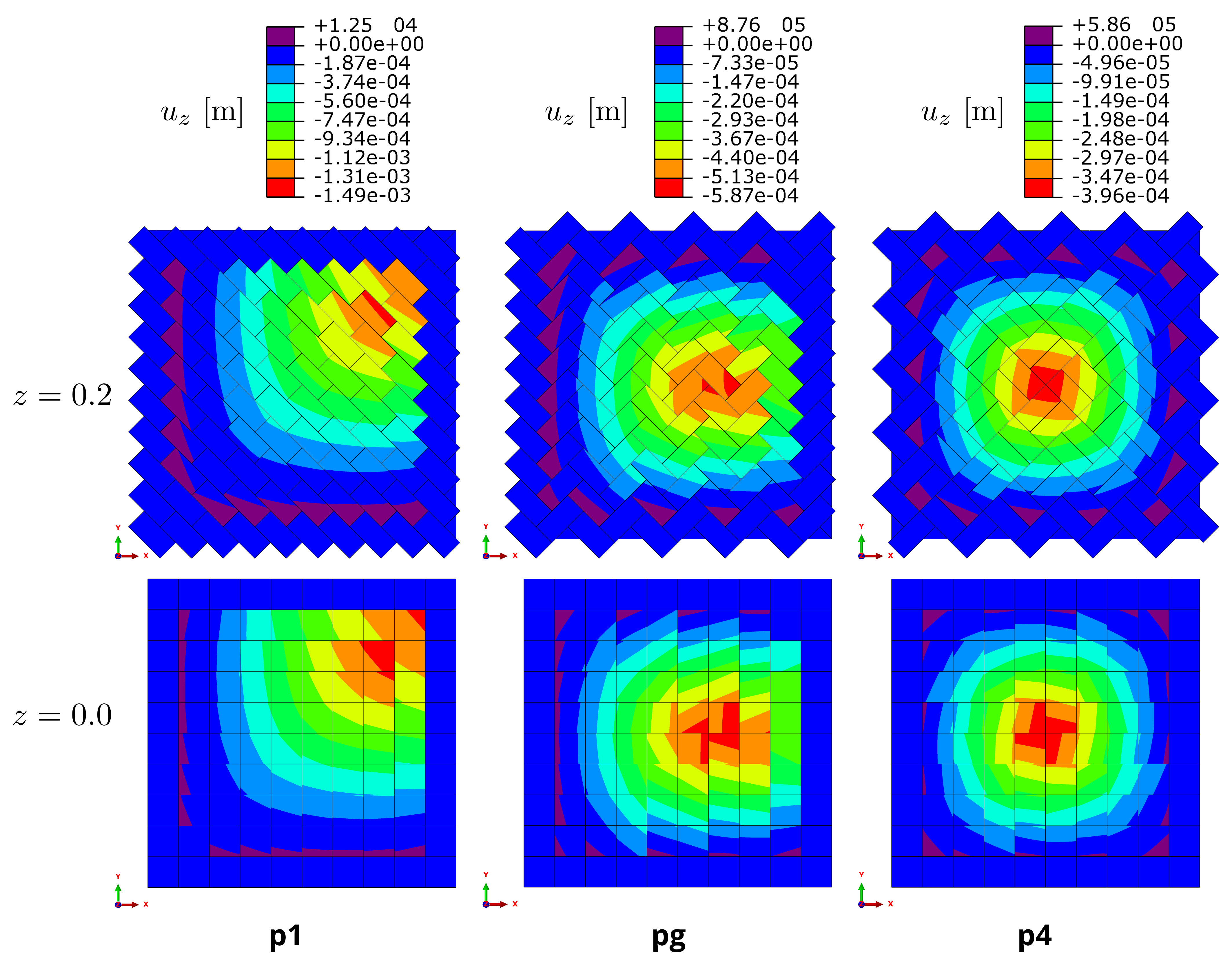
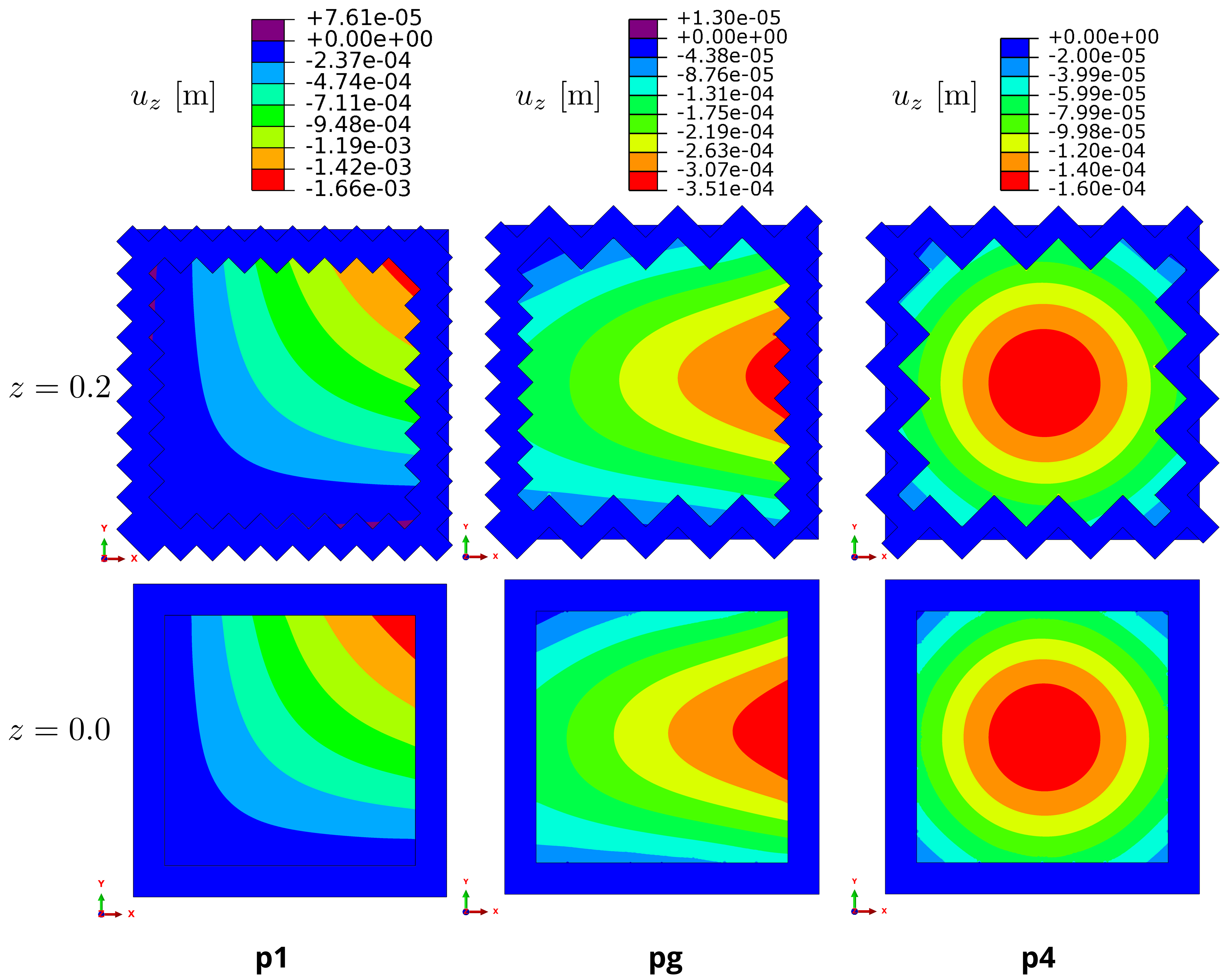
Figure 5 shows the displacement fields uzsubscript𝑢𝑧u_{z} in z𝑧z-direction of the three TIA. The displacement uzsubscript𝑢𝑧u_{z} is shown because the deformation in z𝑧z-direction is most dominant due to the loading direction. The deformation pattern of the interlocking assemblies follows the pattern and the direction of the monolithic plates (Figure 5) but behaves slightly differently due to the modular nature of the assemblies (Figure 6). In p1𝑝1p1, the displacement field spreads along the diagonal form the bottom left corner to the top right corner. The reason for this deformation that all the blocks have the same orientation. In pg𝑝𝑔pg, the deformation spreads from the left boundary in the positive x𝑥x-direction and is limited by the top and bottom boundaries. In p4𝑝4p4, the deformation is equally distributed in all directions and therefore the maximum deflection occurs in the middle. The displacements of the blocks in p1𝑝1p1 at the left and bottom boundary (in purple in Figure 5) are positive, which suggests that their neighbouring blocks leverage them out. This behaviour differs from that of the solid plate. Similar differences between the solid plate and the assemblies pg𝑝𝑔pg and p4𝑝4p4 can be observed. The comparison of the maximum deflections of TIA with the solid plates shows that the p1𝑝1p1 performs surprisingly better, while pg𝑝𝑔pg and p4𝑝4p4 perform about 50% worse. The maximum deflection occurs in front of the right corner block in p1𝑝1p1; slightly to the right of the centre for pg𝑝𝑔pg; and in the centre for p4𝑝4p4. The results show that there is a difference in the displacement distribution between the top and bottom plane of the TIA. Overall it can be concluded that the choice of the assembly, and thus, the shape of the frame, controls the position of the maximum deflection.

Refer to caption
Figure 5: Displacement fields in z𝑧z-direction of the TIA.
Refer to caption
Figure 6: Displacement fields in z𝑧z-direction of the monolithic plates.

Distribution of stresses

Refer to caption
Figure 7: Mises stress distributions in the TIA.
Refer to caption
Figure 8: Mises stress distributions in the monolithic plates.

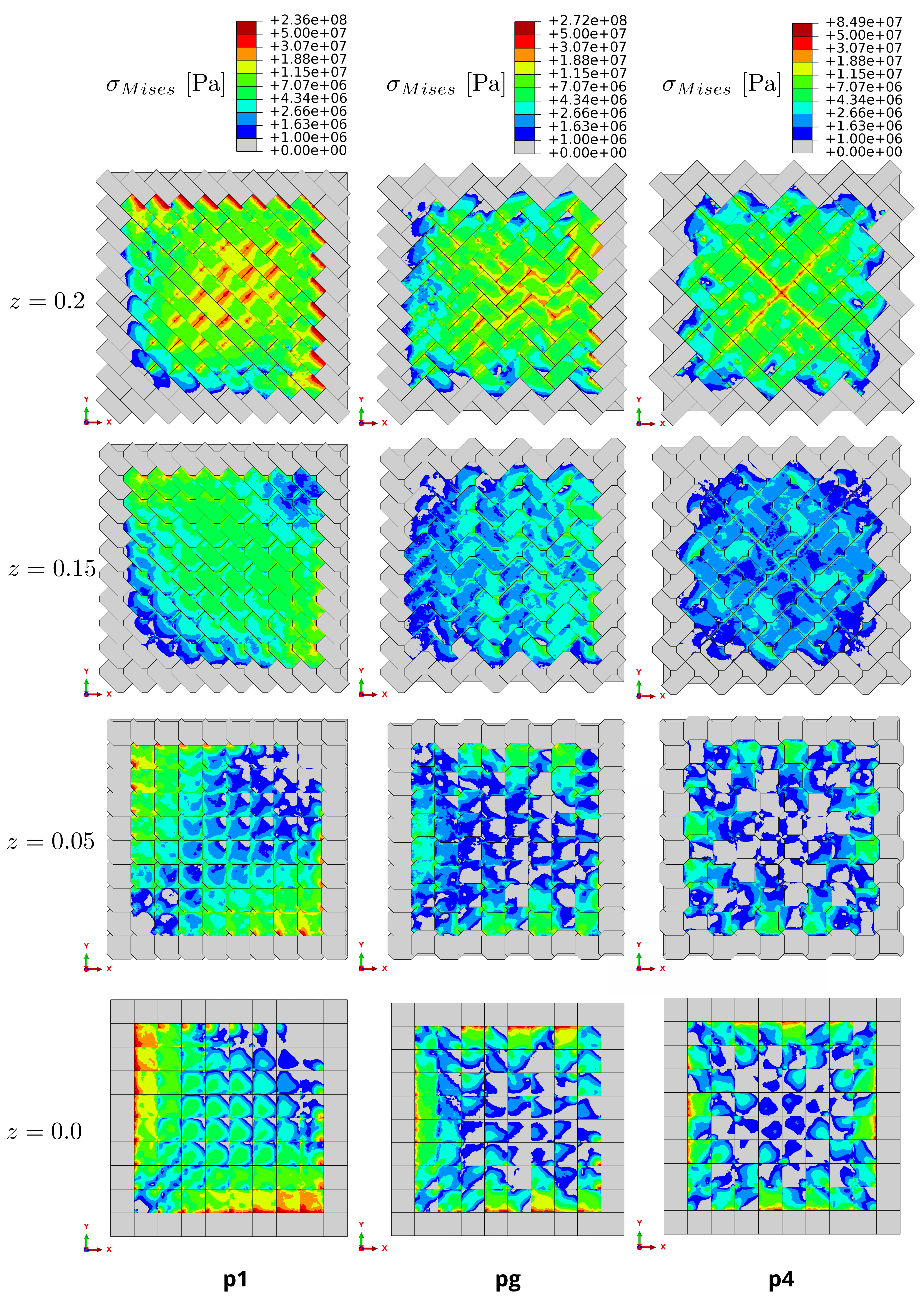
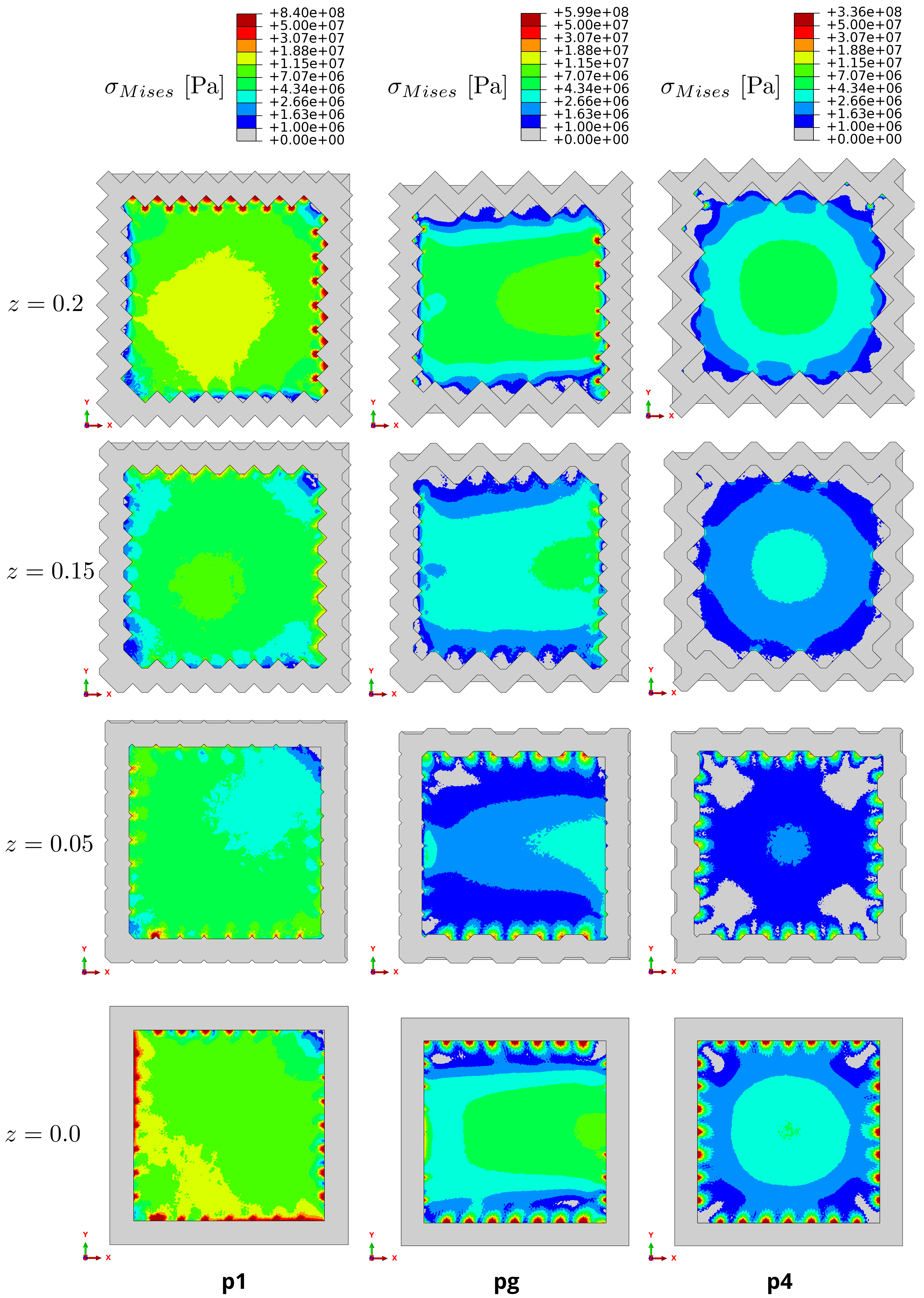
Figure 7 shows the distribution of Mises stresses in the assemblies. The stress distribution is very complex, which is associated with the non-convex geometry of the block. For comparison, the stress distributions in corresponding solid plates are shown in Figure 8. Particularly interesting is the distribution of stresses from the top plane, where the load is applied, to the bottom plane. The results show that different block arrangements strongly influence the stress distribution in the assembly. In the top plane (z=𝑧absentz= 0.2 mtimes0.2meter0.2\text{\,}\mathrm{m}), we can see that the highest stresses occur in the blocks at the top and right boundary as well as centre in p1𝑝1p1; at the centre and at the right boundary in pg𝑝𝑔pg; and only in the middle (forming an ”X”) in the assembly p4𝑝4p4. Similar observations can also be made for the reference solutions (Figure 8). Two major differences can be observed between the monolithic plates and the interlocking assemblies. First, the stress distributions in TIA are discontinuous. This observation is not surprising, of course, since the monolithic plate is assumed to be a continuous medium. And second, below the middle plane z=𝑧absentz= 0.1 mtimes0.1meter0.1\text{\,}\mathrm{m} the majority of the blocks in the assemblies are less stressed than in the monolithic plates, but at the top plane the blocks experience higher stresses. The results also show that where the contact pressure (see Figure 11) between the frame and the assembly is high, the stresses in the blocks are also the highest. From the results it is also evident that assembly p4𝑝4p4 distributes stresses in a more optimal way than pg𝑝𝑔pg or p1𝑝1p1 and is therefore the best of the three options for this particular case. As expected, we observe that the load transfer mechanisms in the regime of compressive stresses are qualitatively similar to those of a monolithic plate, while the load transfer significantly differs in case of tensile stresses (see next paragraph). The reason for this lies in the fact that the gap between neighbouring blocks opens, and thus, contact is lost.

Refer to caption
Figure 9: Normal stresses in y𝑦y-direction of the TIA.

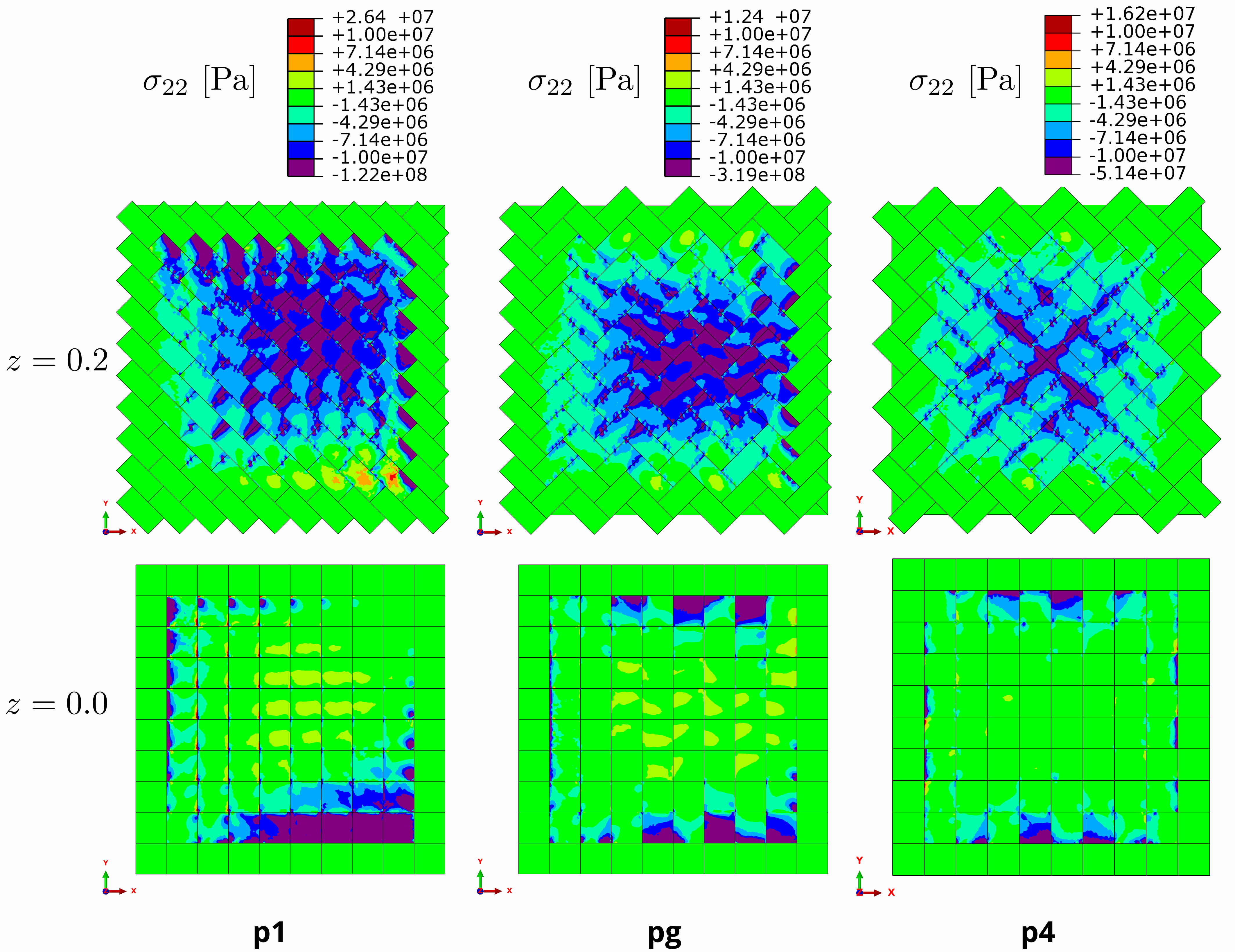
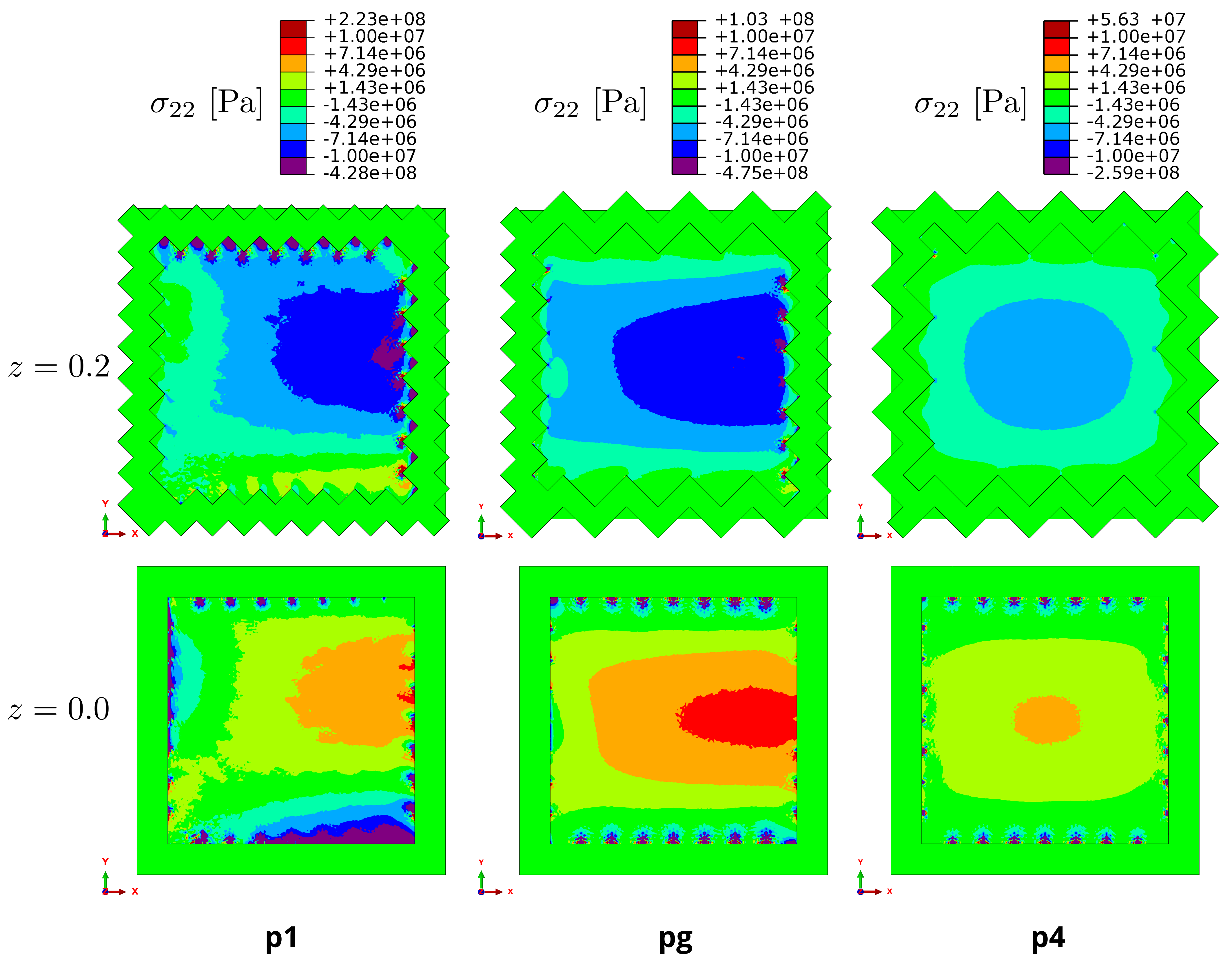
In civil engineering, the assemblies presented in this paper could be used for example as ceilings. Typically, such ceilings are made of concrete, a material that can withstand high compressive but low tensile loads. A solid plate loaded in the transverse direction will bend, resulting in compression in the upper and tension in the lower half of the plate, which is not desirable. To investigate the behaviour of TIA with respect to this problem, we plotted the normal stress field in y𝑦y direction (see Figure 9), which is in our case the first indicator of tension or compression in the material. We can see that the negative stress predominates in the top and bottom planes of the TIA. Comparing this result with the corresponding solid plates (Figure 10), we clearly see the advantage of the TIA.

Refer to caption
Figure 10: Normal stresses in y𝑦y-direction of the monolithic plates.

Contact pressure

Refer to caption
Figure 11: Contact pressure between the blocks in TIA.

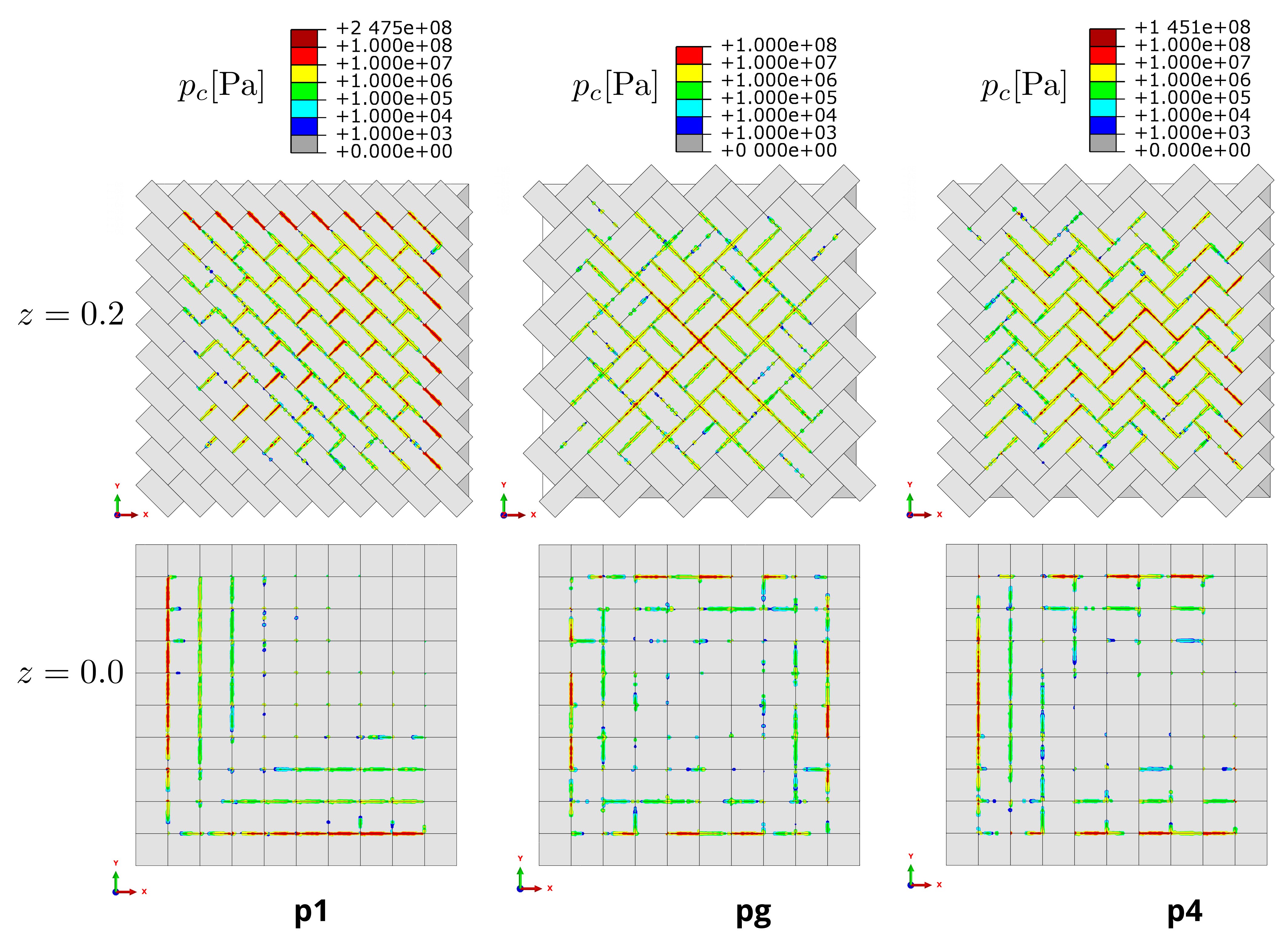
One of the most important questions regarding the interlocking mechanism is: How is an external load transferred through the assembly to the bounding frame? To answer this question, we investigate the contact pressure between the blocks and the frame. The results are shown in Figure 11. Since there is no friction involved, contact pressure indirectly represents the distribution of forces in a TIA. Intuitively, one would think that all peripheral blocks would be equally involved in transferring the external load to the frame. The results show (see Figure 11) that this is not the case. Especially, the assemblies pg𝑝𝑔pg and p4𝑝4p4 show a behaviour that deviates from expectation. Furthermore, the simulations show that load transfer of p1𝑝1p1 occurs over the two boundary edges in the bottom plane and the two opposing boundary edges in the top plane; of pg𝑝𝑔pg over three boundary edges in the bottom plane and the opposing one edge in the top plane; and of p4𝑝4p4 over all boundary edges in the bottom plane only. As the load transfer of p1𝑝1p1 and pg𝑝𝑔pg takes place in two planes, the question arises as to how great the influence of the height of the assembly is on the contact pressure. We have two main findings: First, unlike the monolithic plate, the assembly transfers the load mainly by pressure, and thus the resulting contact forces are higher on average. Second, the load is applied to the frame in a patterned manner, whereas the monolithic plate distributes the load continuously along the frame.

Contact pressure on a single block

Refer to caption
Figure 12: Contact pressure of middle block in the TIA.

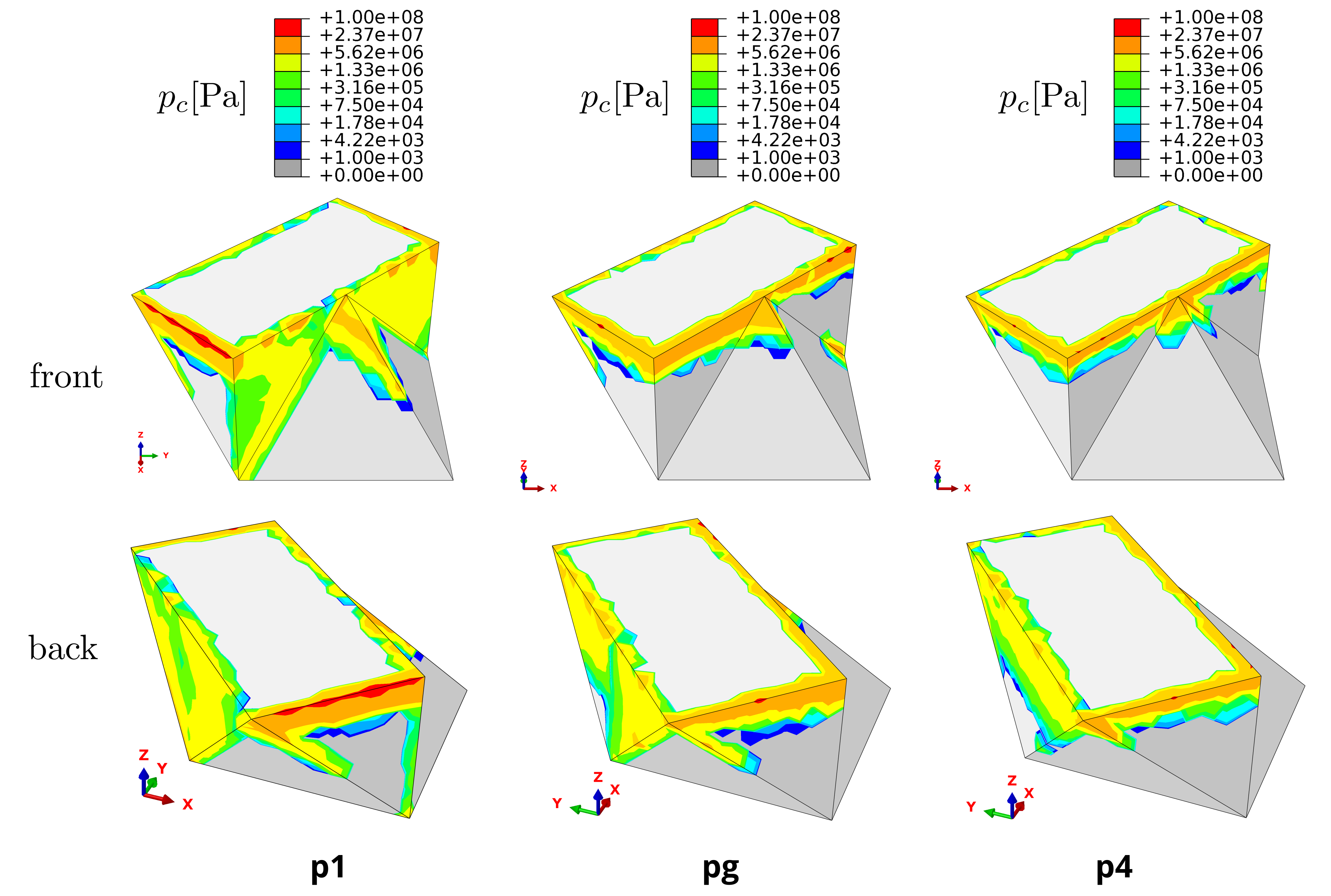
From each TIA, we examined a block near the centre of the assembly to gain insight into which parts of the block are most heavily loaded. For that we simulated the contact pressure present on the surface of the block (Figure 12). The central block was chosen because high contact pressures occur around the centre of the assembly for all TIA. For all three blocks, the highest contact pressure appears at the four edges of the rectangle in the top plane. The contact area is quite narrow, which means that this part of the block is subjected to the greatest load. The lower parts of the blocks are practically not loaded at all. Our results suggest that depending on the position of the block within the overall arrangement, the area of contact of the block with its neighbours may vary.

5 Interlocking Flows

For applications and fast reliable evaluations, it is necessary to predict the quality of a topological interlocking assembly before its manufacturing or even before running simulations. Since FEM simulations are often time consuming, we introduce a fast discrete criterion based on the combinatorial theory of tilings and flow networks, which we call ‘Interlocking Flows’. This is essential for identifying candidates of interlocking assemblies that can be further investigated by using more established methods. Here, the focus lies on load transfer from the assembly onto the frame. For this endeavour, we give a combinatorial interpretation of the results presented in Section 4 and derive a combinatorial model which leads to a stable and fast method for giving a first heuristic of the mechanical performance of an interlocking assembly.

One discrete tool to study topological interlocking assemblies are Directional Blocking Graphs, which are introduced in Wilson (1992); Wilson and Latombe (1994) and investigated in the context of interlocking assemblies in Wang et al. (2018). Here, we give an adapted version of the definition of such a graph for interlocking assemblies by treating the blocks on the frame differently. For this let A={XiiI}𝐴conditional-setsubscript𝑋𝑖𝑖𝐼A=\{X_{i}\mid i\in I\}, be a topological interlocking assembly consisting of blocks Xi3subscript𝑋𝑖superscript3X_{i}\subset\mathbb{R}^{3} indexed by a finite index set I𝐼I with a frame indexed by JI𝐽𝐼J\subset I, the core indexed by CIJ𝐶𝐼𝐽C\coloneqq I\setminus J and d3𝑑superscript3d\in\mathbb{R}^{3} a vector. We say that a block in the core is restrained in direction d𝑑d by another block if shifting the first block in the direction d𝑑d leads to an intersection with the latter block, i.e. for iC𝑖𝐶i\in C and jI𝑗𝐼j\in I, the translated block Xid{xdxXi}subscript𝑋𝑖𝑑conditional-set𝑥𝑑𝑥subscript𝑋𝑖X_{i}-d\coloneqq\{x-d\mid x\in X_{i}\} intersects with Xjsubscript𝑋𝑗X_{j}. Furthermore, we say that a block in the frame restrains itself from moving.

Definition 5.1.

The Directional Blocking Graph (short DGB) 𝒢(A,d)𝒢𝐴𝑑\mathcal{G}(A,d) is defined as the directed graph with

  1. 1.

    vertices given by the set I𝐼I and

  2. 2.

    arcs of the form ij𝑖𝑗i\to j if the block Xisubscript𝑋𝑖X_{i} is restrained by Xjsubscript𝑋𝑗X_{j} in direction d𝑑d for i,jI𝑖𝑗𝐼i,j\in I.

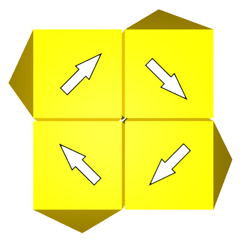
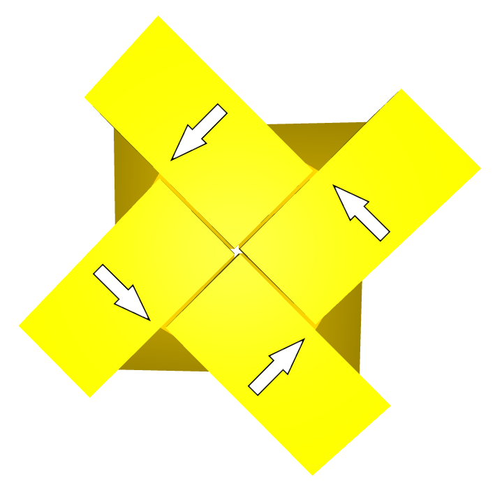
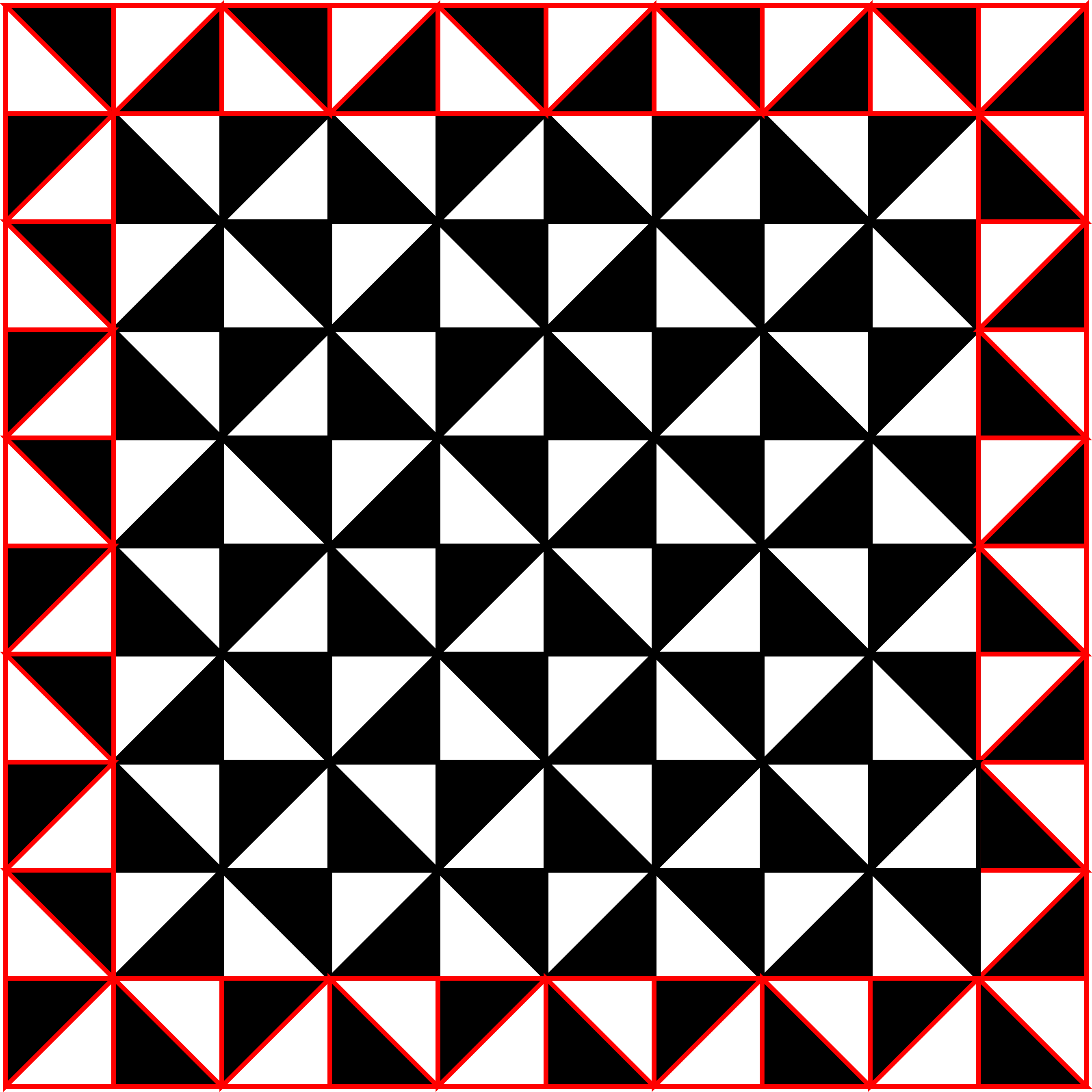
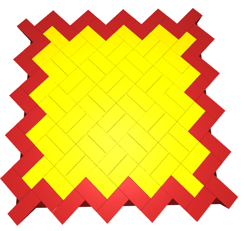
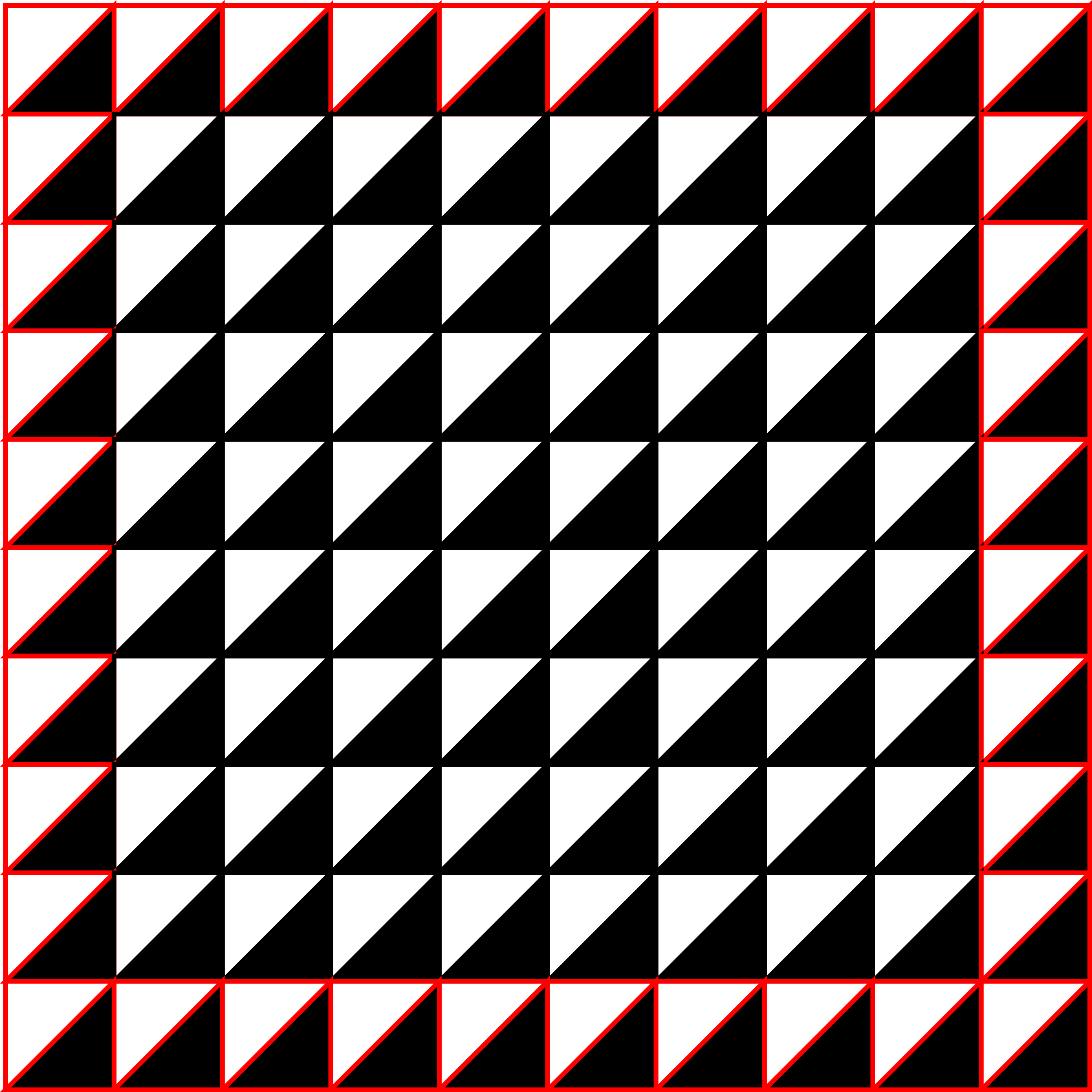
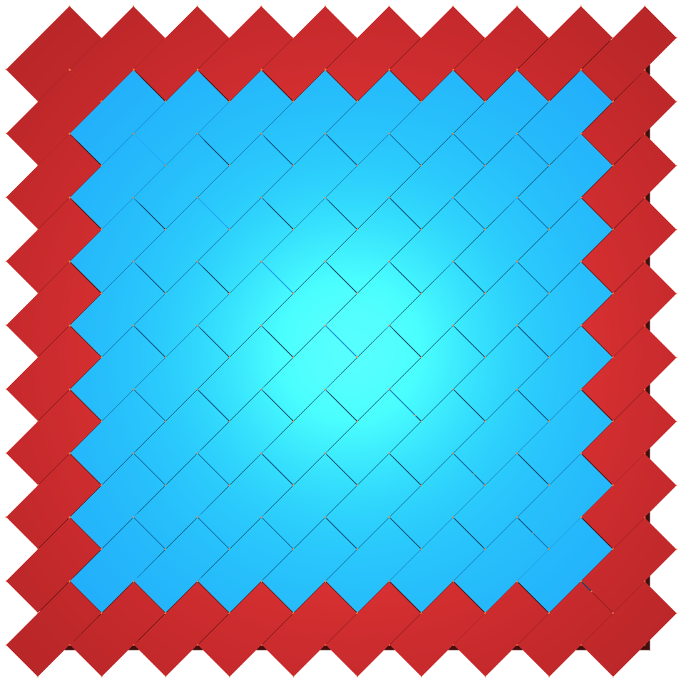
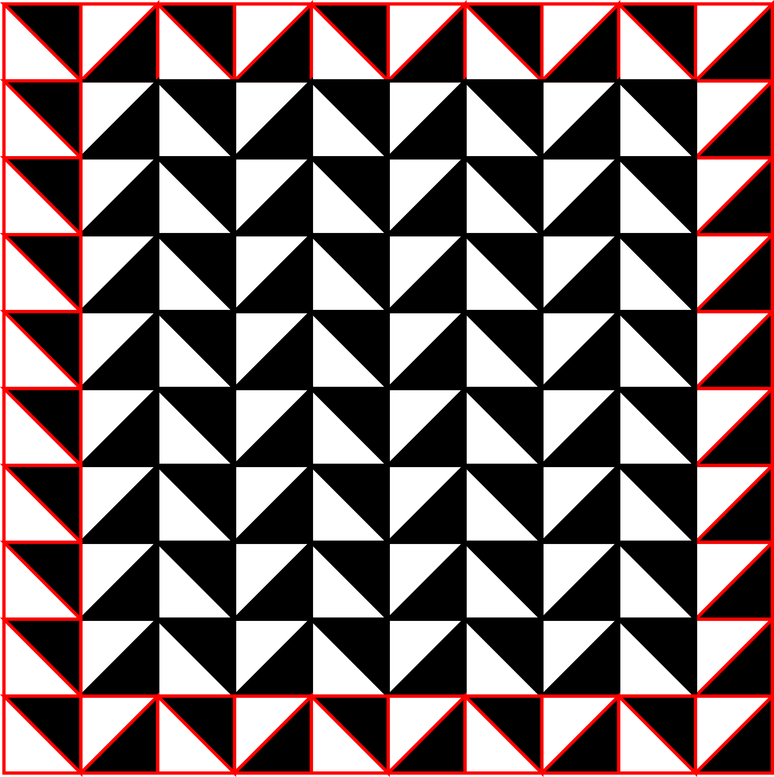
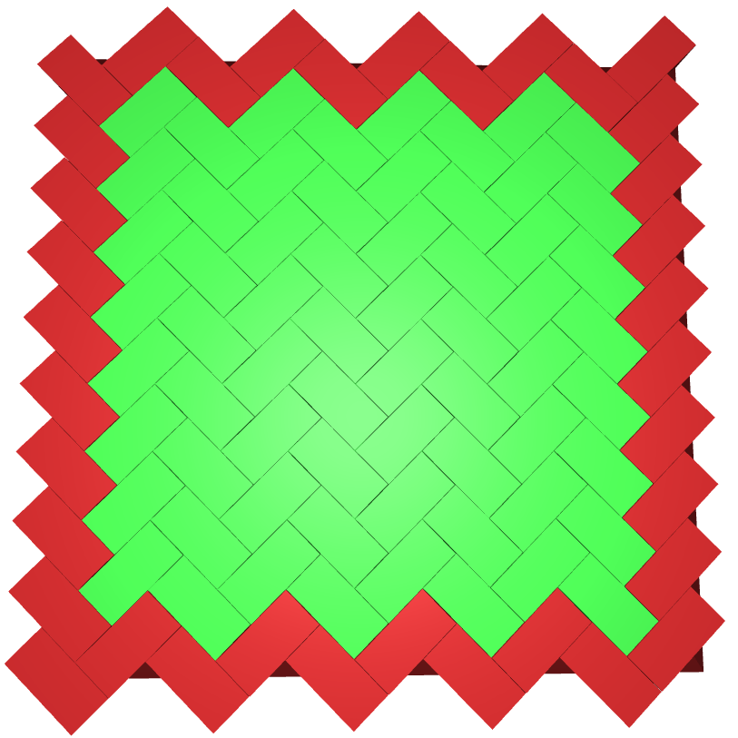
The planar assemblies of copies of the Versatile Block are characterised by Truchet tiles, see Akpanya et al. (2023b). Here a single oriented Truchet tile corresponds to a single oriented Versatile Block. The admissible assemblies are then characterised by the rule that two Truchet tiles only meet at alternating colours. For example, Figure 13(b) displays the p4𝑝4p4 assembly Ap4subscript𝐴𝑝4A_{p4} with |I|=100𝐼100|I|=100 where the frame is marked in red. The corresponding Truchet tiling is given in Figure 13(a).

Refer to caption
(a) p4𝑝4p4 Truchet tiling
Refer to caption
(b) p4𝑝4p4 assembly with frame
Refer to caption
(c) p4𝑝4p4 DGB
00{\definecolor[named]{.}{rgb}{1,0,0}\color[rgb]{1,0,0}\definecolor[named]{pgfstrokecolor}{rgb}{1,0,0}0}00{\definecolor[named]{.}{rgb}{1,0,0}\color[rgb]{1,0,0}\definecolor[named]{pgfstrokecolor}{rgb}{1,0,0}0}00{\definecolor[named]{.}{rgb}{1,0,0}\color[rgb]{1,0,0}\definecolor[named]{pgfstrokecolor}{rgb}{1,0,0}0}00{\definecolor[named]{.}{rgb}{1,0,0}\color[rgb]{1,0,0}\definecolor[named]{pgfstrokecolor}{rgb}{1,0,0}0}00{\definecolor[named]{.}{rgb}{1,0,0}\color[rgb]{1,0,0}\definecolor[named]{pgfstrokecolor}{rgb}{1,0,0}0}00{\definecolor[named]{.}{rgb}{1,0,0}\color[rgb]{1,0,0}\definecolor[named]{pgfstrokecolor}{rgb}{1,0,0}0}00{\definecolor[named]{.}{rgb}{1,0,0}\color[rgb]{1,0,0}\definecolor[named]{pgfstrokecolor}{rgb}{1,0,0}0}00{\definecolor[named]{.}{rgb}{1,0,0}\color[rgb]{1,0,0}\definecolor[named]{pgfstrokecolor}{rgb}{1,0,0}0}00{\definecolor[named]{.}{rgb}{1,0,0}\color[rgb]{1,0,0}\definecolor[named]{pgfstrokecolor}{rgb}{1,0,0}0}00{\definecolor[named]{.}{rgb}{1,0,0}\color[rgb]{1,0,0}\definecolor[named]{pgfstrokecolor}{rgb}{1,0,0}0}00{\definecolor[named]{.}{rgb}{1,0,0}\color[rgb]{1,0,0}\definecolor[named]{pgfstrokecolor}{rgb}{1,0,0}0}11{\definecolor[named]{.}{rgb}{0,0,0}\color[rgb]{0,0,0}\definecolor[named]{pgfstrokecolor}{rgb}{0,0,0}\pgfsys@color@gray@stroke{0}\pgfsys@color@gray@fill{0}1}11{\definecolor[named]{.}{rgb}{0,0,0}\color[rgb]{0,0,0}\definecolor[named]{pgfstrokecolor}{rgb}{0,0,0}\pgfsys@color@gray@stroke{0}\pgfsys@color@gray@fill{0}1}11{\definecolor[named]{.}{rgb}{0,0,0}\color[rgb]{0,0,0}\definecolor[named]{pgfstrokecolor}{rgb}{0,0,0}\pgfsys@color@gray@stroke{0}\pgfsys@color@gray@fill{0}1}11{\definecolor[named]{.}{rgb}{0,0,0}\color[rgb]{0,0,0}\definecolor[named]{pgfstrokecolor}{rgb}{0,0,0}\pgfsys@color@gray@stroke{0}\pgfsys@color@gray@fill{0}1}11{\definecolor[named]{.}{rgb}{0,0,0}\color[rgb]{0,0,0}\definecolor[named]{pgfstrokecolor}{rgb}{0,0,0}\pgfsys@color@gray@stroke{0}\pgfsys@color@gray@fill{0}1}11{\definecolor[named]{.}{rgb}{0,0,0}\color[rgb]{0,0,0}\definecolor[named]{pgfstrokecolor}{rgb}{0,0,0}\pgfsys@color@gray@stroke{0}\pgfsys@color@gray@fill{0}1}11{\definecolor[named]{.}{rgb}{0,0,0}\color[rgb]{0,0,0}\definecolor[named]{pgfstrokecolor}{rgb}{0,0,0}\pgfsys@color@gray@stroke{0}\pgfsys@color@gray@fill{0}1}11{\definecolor[named]{.}{rgb}{0,0,0}\color[rgb]{0,0,0}\definecolor[named]{pgfstrokecolor}{rgb}{0,0,0}\pgfsys@color@gray@stroke{0}\pgfsys@color@gray@fill{0}1}00{\definecolor[named]{.}{rgb}{1,0,0}\color[rgb]{1,0,0}\definecolor[named]{pgfstrokecolor}{rgb}{1,0,0}0}00{\definecolor[named]{.}{rgb}{1,0,0}\color[rgb]{1,0,0}\definecolor[named]{pgfstrokecolor}{rgb}{1,0,0}0}11{\definecolor[named]{.}{rgb}{0,0,0}\color[rgb]{0,0,0}\definecolor[named]{pgfstrokecolor}{rgb}{0,0,0}\pgfsys@color@gray@stroke{0}\pgfsys@color@gray@fill{0}1}11{\definecolor[named]{.}{rgb}{0,0,0}\color[rgb]{0,0,0}\definecolor[named]{pgfstrokecolor}{rgb}{0,0,0}\pgfsys@color@gray@stroke{0}\pgfsys@color@gray@fill{0}1}11{\definecolor[named]{.}{rgb}{0,0,0}\color[rgb]{0,0,0}\definecolor[named]{pgfstrokecolor}{rgb}{0,0,0}\pgfsys@color@gray@stroke{0}\pgfsys@color@gray@fill{0}1}11{\definecolor[named]{.}{rgb}{0,0,0}\color[rgb]{0,0,0}\definecolor[named]{pgfstrokecolor}{rgb}{0,0,0}\pgfsys@color@gray@stroke{0}\pgfsys@color@gray@fill{0}1}11{\definecolor[named]{.}{rgb}{0,0,0}\color[rgb]{0,0,0}\definecolor[named]{pgfstrokecolor}{rgb}{0,0,0}\pgfsys@color@gray@stroke{0}\pgfsys@color@gray@fill{0}1}11{\definecolor[named]{.}{rgb}{0,0,0}\color[rgb]{0,0,0}\definecolor[named]{pgfstrokecolor}{rgb}{0,0,0}\pgfsys@color@gray@stroke{0}\pgfsys@color@gray@fill{0}1}11{\definecolor[named]{.}{rgb}{0,0,0}\color[rgb]{0,0,0}\definecolor[named]{pgfstrokecolor}{rgb}{0,0,0}\pgfsys@color@gray@stroke{0}\pgfsys@color@gray@fill{0}1}11{\definecolor[named]{.}{rgb}{0,0,0}\color[rgb]{0,0,0}\definecolor[named]{pgfstrokecolor}{rgb}{0,0,0}\pgfsys@color@gray@stroke{0}\pgfsys@color@gray@fill{0}1}00{\definecolor[named]{.}{rgb}{1,0,0}\color[rgb]{1,0,0}\definecolor[named]{pgfstrokecolor}{rgb}{1,0,0}0}00{\definecolor[named]{.}{rgb}{1,0,0}\color[rgb]{1,0,0}\definecolor[named]{pgfstrokecolor}{rgb}{1,0,0}0}11{\definecolor[named]{.}{rgb}{0,0,0}\color[rgb]{0,0,0}\definecolor[named]{pgfstrokecolor}{rgb}{0,0,0}\pgfsys@color@gray@stroke{0}\pgfsys@color@gray@fill{0}1}11{\definecolor[named]{.}{rgb}{0,0,0}\color[rgb]{0,0,0}\definecolor[named]{pgfstrokecolor}{rgb}{0,0,0}\pgfsys@color@gray@stroke{0}\pgfsys@color@gray@fill{0}1}11{\definecolor[named]{.}{rgb}{0,0,0}\color[rgb]{0,0,0}\definecolor[named]{pgfstrokecolor}{rgb}{0,0,0}\pgfsys@color@gray@stroke{0}\pgfsys@color@gray@fill{0}1}11{\definecolor[named]{.}{rgb}{0,0,0}\color[rgb]{0,0,0}\definecolor[named]{pgfstrokecolor}{rgb}{0,0,0}\pgfsys@color@gray@stroke{0}\pgfsys@color@gray@fill{0}1}11{\definecolor[named]{.}{rgb}{0,0,0}\color[rgb]{0,0,0}\definecolor[named]{pgfstrokecolor}{rgb}{0,0,0}\pgfsys@color@gray@stroke{0}\pgfsys@color@gray@fill{0}1}11{\definecolor[named]{.}{rgb}{0,0,0}\color[rgb]{0,0,0}\definecolor[named]{pgfstrokecolor}{rgb}{0,0,0}\pgfsys@color@gray@stroke{0}\pgfsys@color@gray@fill{0}1}11{\definecolor[named]{.}{rgb}{0,0,0}\color[rgb]{0,0,0}\definecolor[named]{pgfstrokecolor}{rgb}{0,0,0}\pgfsys@color@gray@stroke{0}\pgfsys@color@gray@fill{0}1}11{\definecolor[named]{.}{rgb}{0,0,0}\color[rgb]{0,0,0}\definecolor[named]{pgfstrokecolor}{rgb}{0,0,0}\pgfsys@color@gray@stroke{0}\pgfsys@color@gray@fill{0}1}00{\definecolor[named]{.}{rgb}{1,0,0}\color[rgb]{1,0,0}\definecolor[named]{pgfstrokecolor}{rgb}{1,0,0}0}00{\definecolor[named]{.}{rgb}{1,0,0}\color[rgb]{1,0,0}\definecolor[named]{pgfstrokecolor}{rgb}{1,0,0}0}11{\definecolor[named]{.}{rgb}{0,0,0}\color[rgb]{0,0,0}\definecolor[named]{pgfstrokecolor}{rgb}{0,0,0}\pgfsys@color@gray@stroke{0}\pgfsys@color@gray@fill{0}1}11{\definecolor[named]{.}{rgb}{0,0,0}\color[rgb]{0,0,0}\definecolor[named]{pgfstrokecolor}{rgb}{0,0,0}\pgfsys@color@gray@stroke{0}\pgfsys@color@gray@fill{0}1}11{\definecolor[named]{.}{rgb}{0,0,0}\color[rgb]{0,0,0}\definecolor[named]{pgfstrokecolor}{rgb}{0,0,0}\pgfsys@color@gray@stroke{0}\pgfsys@color@gray@fill{0}1}11{\definecolor[named]{.}{rgb}{0,0,0}\color[rgb]{0,0,0}\definecolor[named]{pgfstrokecolor}{rgb}{0,0,0}\pgfsys@color@gray@stroke{0}\pgfsys@color@gray@fill{0}1}11{\definecolor[named]{.}{rgb}{0,0,0}\color[rgb]{0,0,0}\definecolor[named]{pgfstrokecolor}{rgb}{0,0,0}\pgfsys@color@gray@stroke{0}\pgfsys@color@gray@fill{0}1}11{\definecolor[named]{.}{rgb}{0,0,0}\color[rgb]{0,0,0}\definecolor[named]{pgfstrokecolor}{rgb}{0,0,0}\pgfsys@color@gray@stroke{0}\pgfsys@color@gray@fill{0}1}11{\definecolor[named]{.}{rgb}{0,0,0}\color[rgb]{0,0,0}\definecolor[named]{pgfstrokecolor}{rgb}{0,0,0}\pgfsys@color@gray@stroke{0}\pgfsys@color@gray@fill{0}1}11{\definecolor[named]{.}{rgb}{0,0,0}\color[rgb]{0,0,0}\definecolor[named]{pgfstrokecolor}{rgb}{0,0,0}\pgfsys@color@gray@stroke{0}\pgfsys@color@gray@fill{0}1}00{\definecolor[named]{.}{rgb}{1,0,0}\color[rgb]{1,0,0}\definecolor[named]{pgfstrokecolor}{rgb}{1,0,0}0}00{\definecolor[named]{.}{rgb}{1,0,0}\color[rgb]{1,0,0}\definecolor[named]{pgfstrokecolor}{rgb}{1,0,0}0}11{\definecolor[named]{.}{rgb}{0,0,0}\color[rgb]{0,0,0}\definecolor[named]{pgfstrokecolor}{rgb}{0,0,0}\pgfsys@color@gray@stroke{0}\pgfsys@color@gray@fill{0}1}11{\definecolor[named]{.}{rgb}{0,0,0}\color[rgb]{0,0,0}\definecolor[named]{pgfstrokecolor}{rgb}{0,0,0}\pgfsys@color@gray@stroke{0}\pgfsys@color@gray@fill{0}1}11{\definecolor[named]{.}{rgb}{0,0,0}\color[rgb]{0,0,0}\definecolor[named]{pgfstrokecolor}{rgb}{0,0,0}\pgfsys@color@gray@stroke{0}\pgfsys@color@gray@fill{0}1}11{\definecolor[named]{.}{rgb}{0,0,0}\color[rgb]{0,0,0}\definecolor[named]{pgfstrokecolor}{rgb}{0,0,0}\pgfsys@color@gray@stroke{0}\pgfsys@color@gray@fill{0}1}11{\definecolor[named]{.}{rgb}{0,0,0}\color[rgb]{0,0,0}\definecolor[named]{pgfstrokecolor}{rgb}{0,0,0}\pgfsys@color@gray@stroke{0}\pgfsys@color@gray@fill{0}1}11{\definecolor[named]{.}{rgb}{0,0,0}\color[rgb]{0,0,0}\definecolor[named]{pgfstrokecolor}{rgb}{0,0,0}\pgfsys@color@gray@stroke{0}\pgfsys@color@gray@fill{0}1}11{\definecolor[named]{.}{rgb}{0,0,0}\color[rgb]{0,0,0}\definecolor[named]{pgfstrokecolor}{rgb}{0,0,0}\pgfsys@color@gray@stroke{0}\pgfsys@color@gray@fill{0}1}11{\definecolor[named]{.}{rgb}{0,0,0}\color[rgb]{0,0,0}\definecolor[named]{pgfstrokecolor}{rgb}{0,0,0}\pgfsys@color@gray@stroke{0}\pgfsys@color@gray@fill{0}1}00{\definecolor[named]{.}{rgb}{1,0,0}\color[rgb]{1,0,0}\definecolor[named]{pgfstrokecolor}{rgb}{1,0,0}0}00{\definecolor[named]{.}{rgb}{1,0,0}\color[rgb]{1,0,0}\definecolor[named]{pgfstrokecolor}{rgb}{1,0,0}0}11{\definecolor[named]{.}{rgb}{0,0,0}\color[rgb]{0,0,0}\definecolor[named]{pgfstrokecolor}{rgb}{0,0,0}\pgfsys@color@gray@stroke{0}\pgfsys@color@gray@fill{0}1}11{\definecolor[named]{.}{rgb}{0,0,0}\color[rgb]{0,0,0}\definecolor[named]{pgfstrokecolor}{rgb}{0,0,0}\pgfsys@color@gray@stroke{0}\pgfsys@color@gray@fill{0}1}11{\definecolor[named]{.}{rgb}{0,0,0}\color[rgb]{0,0,0}\definecolor[named]{pgfstrokecolor}{rgb}{0,0,0}\pgfsys@color@gray@stroke{0}\pgfsys@color@gray@fill{0}1}11{\definecolor[named]{.}{rgb}{0,0,0}\color[rgb]{0,0,0}\definecolor[named]{pgfstrokecolor}{rgb}{0,0,0}\pgfsys@color@gray@stroke{0}\pgfsys@color@gray@fill{0}1}11{\definecolor[named]{.}{rgb}{0,0,0}\color[rgb]{0,0,0}\definecolor[named]{pgfstrokecolor}{rgb}{0,0,0}\pgfsys@color@gray@stroke{0}\pgfsys@color@gray@fill{0}1}11{\definecolor[named]{.}{rgb}{0,0,0}\color[rgb]{0,0,0}\definecolor[named]{pgfstrokecolor}{rgb}{0,0,0}\pgfsys@color@gray@stroke{0}\pgfsys@color@gray@fill{0}1}11{\definecolor[named]{.}{rgb}{0,0,0}\color[rgb]{0,0,0}\definecolor[named]{pgfstrokecolor}{rgb}{0,0,0}\pgfsys@color@gray@stroke{0}\pgfsys@color@gray@fill{0}1}11{\definecolor[named]{.}{rgb}{0,0,0}\color[rgb]{0,0,0}\definecolor[named]{pgfstrokecolor}{rgb}{0,0,0}\pgfsys@color@gray@stroke{0}\pgfsys@color@gray@fill{0}1}00{\definecolor[named]{.}{rgb}{1,0,0}\color[rgb]{1,0,0}\definecolor[named]{pgfstrokecolor}{rgb}{1,0,0}0}00{\definecolor[named]{.}{rgb}{1,0,0}\color[rgb]{1,0,0}\definecolor[named]{pgfstrokecolor}{rgb}{1,0,0}0}11{\definecolor[named]{.}{rgb}{0,0,0}\color[rgb]{0,0,0}\definecolor[named]{pgfstrokecolor}{rgb}{0,0,0}\pgfsys@color@gray@stroke{0}\pgfsys@color@gray@fill{0}1}11{\definecolor[named]{.}{rgb}{0,0,0}\color[rgb]{0,0,0}\definecolor[named]{pgfstrokecolor}{rgb}{0,0,0}\pgfsys@color@gray@stroke{0}\pgfsys@color@gray@fill{0}1}11{\definecolor[named]{.}{rgb}{0,0,0}\color[rgb]{0,0,0}\definecolor[named]{pgfstrokecolor}{rgb}{0,0,0}\pgfsys@color@gray@stroke{0}\pgfsys@color@gray@fill{0}1}11{\definecolor[named]{.}{rgb}{0,0,0}\color[rgb]{0,0,0}\definecolor[named]{pgfstrokecolor}{rgb}{0,0,0}\pgfsys@color@gray@stroke{0}\pgfsys@color@gray@fill{0}1}11{\definecolor[named]{.}{rgb}{0,0,0}\color[rgb]{0,0,0}\definecolor[named]{pgfstrokecolor}{rgb}{0,0,0}\pgfsys@color@gray@stroke{0}\pgfsys@color@gray@fill{0}1}11{\definecolor[named]{.}{rgb}{0,0,0}\color[rgb]{0,0,0}\definecolor[named]{pgfstrokecolor}{rgb}{0,0,0}\pgfsys@color@gray@stroke{0}\pgfsys@color@gray@fill{0}1}11{\definecolor[named]{.}{rgb}{0,0,0}\color[rgb]{0,0,0}\definecolor[named]{pgfstrokecolor}{rgb}{0,0,0}\pgfsys@color@gray@stroke{0}\pgfsys@color@gray@fill{0}1}11{\definecolor[named]{.}{rgb}{0,0,0}\color[rgb]{0,0,0}\definecolor[named]{pgfstrokecolor}{rgb}{0,0,0}\pgfsys@color@gray@stroke{0}\pgfsys@color@gray@fill{0}1}00{\definecolor[named]{.}{rgb}{1,0,0}\color[rgb]{1,0,0}\definecolor[named]{pgfstrokecolor}{rgb}{1,0,0}0}00{\definecolor[named]{.}{rgb}{1,0,0}\color[rgb]{1,0,0}\definecolor[named]{pgfstrokecolor}{rgb}{1,0,0}0}11{\definecolor[named]{.}{rgb}{0,0,0}\color[rgb]{0,0,0}\definecolor[named]{pgfstrokecolor}{rgb}{0,0,0}\pgfsys@color@gray@stroke{0}\pgfsys@color@gray@fill{0}1}11{\definecolor[named]{.}{rgb}{0,0,0}\color[rgb]{0,0,0}\definecolor[named]{pgfstrokecolor}{rgb}{0,0,0}\pgfsys@color@gray@stroke{0}\pgfsys@color@gray@fill{0}1}11{\definecolor[named]{.}{rgb}{0,0,0}\color[rgb]{0,0,0}\definecolor[named]{pgfstrokecolor}{rgb}{0,0,0}\pgfsys@color@gray@stroke{0}\pgfsys@color@gray@fill{0}1}11{\definecolor[named]{.}{rgb}{0,0,0}\color[rgb]{0,0,0}\definecolor[named]{pgfstrokecolor}{rgb}{0,0,0}\pgfsys@color@gray@stroke{0}\pgfsys@color@gray@fill{0}1}11{\definecolor[named]{.}{rgb}{0,0,0}\color[rgb]{0,0,0}\definecolor[named]{pgfstrokecolor}{rgb}{0,0,0}\pgfsys@color@gray@stroke{0}\pgfsys@color@gray@fill{0}1}11{\definecolor[named]{.}{rgb}{0,0,0}\color[rgb]{0,0,0}\definecolor[named]{pgfstrokecolor}{rgb}{0,0,0}\pgfsys@color@gray@stroke{0}\pgfsys@color@gray@fill{0}1}11{\definecolor[named]{.}{rgb}{0,0,0}\color[rgb]{0,0,0}\definecolor[named]{pgfstrokecolor}{rgb}{0,0,0}\pgfsys@color@gray@stroke{0}\pgfsys@color@gray@fill{0}1}11{\definecolor[named]{.}{rgb}{0,0,0}\color[rgb]{0,0,0}\definecolor[named]{pgfstrokecolor}{rgb}{0,0,0}\pgfsys@color@gray@stroke{0}\pgfsys@color@gray@fill{0}1}00{\definecolor[named]{.}{rgb}{1,0,0}\color[rgb]{1,0,0}\definecolor[named]{pgfstrokecolor}{rgb}{1,0,0}0}00{\definecolor[named]{.}{rgb}{1,0,0}\color[rgb]{1,0,0}\definecolor[named]{pgfstrokecolor}{rgb}{1,0,0}0}00{\definecolor[named]{.}{rgb}{1,0,0}\color[rgb]{1,0,0}\definecolor[named]{pgfstrokecolor}{rgb}{1,0,0}0}00{\definecolor[named]{.}{rgb}{1,0,0}\color[rgb]{1,0,0}\definecolor[named]{pgfstrokecolor}{rgb}{1,0,0}0}00{\definecolor[named]{.}{rgb}{1,0,0}\color[rgb]{1,0,0}\definecolor[named]{pgfstrokecolor}{rgb}{1,0,0}0}00{\definecolor[named]{.}{rgb}{1,0,0}\color[rgb]{1,0,0}\definecolor[named]{pgfstrokecolor}{rgb}{1,0,0}0}00{\definecolor[named]{.}{rgb}{1,0,0}\color[rgb]{1,0,0}\definecolor[named]{pgfstrokecolor}{rgb}{1,0,0}0}00{\definecolor[named]{.}{rgb}{1,0,0}\color[rgb]{1,0,0}\definecolor[named]{pgfstrokecolor}{rgb}{1,0,0}0}00{\definecolor[named]{.}{rgb}{1,0,0}\color[rgb]{1,0,0}\definecolor[named]{pgfstrokecolor}{rgb}{1,0,0}0}00{\definecolor[named]{.}{rgb}{1,0,0}\color[rgb]{1,0,0}\definecolor[named]{pgfstrokecolor}{rgb}{1,0,0}0}00{\definecolor[named]{.}{rgb}{1,0,0}\color[rgb]{1,0,0}\definecolor[named]{pgfstrokecolor}{rgb}{1,0,0}0}
(d) xI10010×10𝑥superscript𝐼superscript100superscript1010x\in\mathbb{R}^{I}\cong\mathbb{R}^{100}\cong\mathbb{R}^{10\times 10}
00{\definecolor[named]{.}{rgb}{1,0,0}\color[rgb]{1,0,0}\definecolor[named]{pgfstrokecolor}{rgb}{1,0,0}0}1212{\definecolor[named]{.}{rgb}{1,0,0}\color[rgb]{1,0,0}\definecolor[named]{pgfstrokecolor}{rgb}{1,0,0}\frac{1}{2}}00{\definecolor[named]{.}{rgb}{1,0,0}\color[rgb]{1,0,0}\definecolor[named]{pgfstrokecolor}{rgb}{1,0,0}0}1212{\definecolor[named]{.}{rgb}{1,0,0}\color[rgb]{1,0,0}\definecolor[named]{pgfstrokecolor}{rgb}{1,0,0}\frac{1}{2}}00{\definecolor[named]{.}{rgb}{1,0,0}\color[rgb]{1,0,0}\definecolor[named]{pgfstrokecolor}{rgb}{1,0,0}0}1212{\definecolor[named]{.}{rgb}{1,0,0}\color[rgb]{1,0,0}\definecolor[named]{pgfstrokecolor}{rgb}{1,0,0}\frac{1}{2}}00{\definecolor[named]{.}{rgb}{1,0,0}\color[rgb]{1,0,0}\definecolor[named]{pgfstrokecolor}{rgb}{1,0,0}0}1212{\definecolor[named]{.}{rgb}{1,0,0}\color[rgb]{1,0,0}\definecolor[named]{pgfstrokecolor}{rgb}{1,0,0}\frac{1}{2}}00{\definecolor[named]{.}{rgb}{1,0,0}\color[rgb]{1,0,0}\definecolor[named]{pgfstrokecolor}{rgb}{1,0,0}0}00{\definecolor[named]{.}{rgb}{1,0,0}\color[rgb]{1,0,0}\definecolor[named]{pgfstrokecolor}{rgb}{1,0,0}0}00{\definecolor[named]{.}{rgb}{1,0,0}\color[rgb]{1,0,0}\definecolor[named]{pgfstrokecolor}{rgb}{1,0,0}0}1212{\definecolor[named]{.}{rgb}{0,0,0}\color[rgb]{0,0,0}\definecolor[named]{pgfstrokecolor}{rgb}{0,0,0}\pgfsys@color@gray@stroke{0}\pgfsys@color@gray@fill{0}\frac{1}{2}}1212{\definecolor[named]{.}{rgb}{0,0,0}\color[rgb]{0,0,0}\definecolor[named]{pgfstrokecolor}{rgb}{0,0,0}\pgfsys@color@gray@stroke{0}\pgfsys@color@gray@fill{0}\frac{1}{2}}11{\definecolor[named]{.}{rgb}{0,0,0}\color[rgb]{0,0,0}\definecolor[named]{pgfstrokecolor}{rgb}{0,0,0}\pgfsys@color@gray@stroke{0}\pgfsys@color@gray@fill{0}1}1212{\definecolor[named]{.}{rgb}{0,0,0}\color[rgb]{0,0,0}\definecolor[named]{pgfstrokecolor}{rgb}{0,0,0}\pgfsys@color@gray@stroke{0}\pgfsys@color@gray@fill{0}\frac{1}{2}}11{\definecolor[named]{.}{rgb}{0,0,0}\color[rgb]{0,0,0}\definecolor[named]{pgfstrokecolor}{rgb}{0,0,0}\pgfsys@color@gray@stroke{0}\pgfsys@color@gray@fill{0}1}1212{\definecolor[named]{.}{rgb}{0,0,0}\color[rgb]{0,0,0}\definecolor[named]{pgfstrokecolor}{rgb}{0,0,0}\pgfsys@color@gray@stroke{0}\pgfsys@color@gray@fill{0}\frac{1}{2}}11{\definecolor[named]{.}{rgb}{0,0,0}\color[rgb]{0,0,0}\definecolor[named]{pgfstrokecolor}{rgb}{0,0,0}\pgfsys@color@gray@stroke{0}\pgfsys@color@gray@fill{0}1}1212{\definecolor[named]{.}{rgb}{0,0,0}\color[rgb]{0,0,0}\definecolor[named]{pgfstrokecolor}{rgb}{0,0,0}\pgfsys@color@gray@stroke{0}\pgfsys@color@gray@fill{0}\frac{1}{2}}1212{\definecolor[named]{.}{rgb}{1,0,0}\color[rgb]{1,0,0}\definecolor[named]{pgfstrokecolor}{rgb}{1,0,0}\frac{1}{2}}1212{\definecolor[named]{.}{rgb}{1,0,0}\color[rgb]{1,0,0}\definecolor[named]{pgfstrokecolor}{rgb}{1,0,0}\frac{1}{2}}11{\definecolor[named]{.}{rgb}{0,0,0}\color[rgb]{0,0,0}\definecolor[named]{pgfstrokecolor}{rgb}{0,0,0}\pgfsys@color@gray@stroke{0}\pgfsys@color@gray@fill{0}1}11{\definecolor[named]{.}{rgb}{0,0,0}\color[rgb]{0,0,0}\definecolor[named]{pgfstrokecolor}{rgb}{0,0,0}\pgfsys@color@gray@stroke{0}\pgfsys@color@gray@fill{0}1}11{\definecolor[named]{.}{rgb}{0,0,0}\color[rgb]{0,0,0}\definecolor[named]{pgfstrokecolor}{rgb}{0,0,0}\pgfsys@color@gray@stroke{0}\pgfsys@color@gray@fill{0}1}11{\definecolor[named]{.}{rgb}{0,0,0}\color[rgb]{0,0,0}\definecolor[named]{pgfstrokecolor}{rgb}{0,0,0}\pgfsys@color@gray@stroke{0}\pgfsys@color@gray@fill{0}1}11{\definecolor[named]{.}{rgb}{0,0,0}\color[rgb]{0,0,0}\definecolor[named]{pgfstrokecolor}{rgb}{0,0,0}\pgfsys@color@gray@stroke{0}\pgfsys@color@gray@fill{0}1}11{\definecolor[named]{.}{rgb}{0,0,0}\color[rgb]{0,0,0}\definecolor[named]{pgfstrokecolor}{rgb}{0,0,0}\pgfsys@color@gray@stroke{0}\pgfsys@color@gray@fill{0}1}11{\definecolor[named]{.}{rgb}{0,0,0}\color[rgb]{0,0,0}\definecolor[named]{pgfstrokecolor}{rgb}{0,0,0}\pgfsys@color@gray@stroke{0}\pgfsys@color@gray@fill{0}1}1212{\definecolor[named]{.}{rgb}{0,0,0}\color[rgb]{0,0,0}\definecolor[named]{pgfstrokecolor}{rgb}{0,0,0}\pgfsys@color@gray@stroke{0}\pgfsys@color@gray@fill{0}\frac{1}{2}}00{\definecolor[named]{.}{rgb}{1,0,0}\color[rgb]{1,0,0}\definecolor[named]{pgfstrokecolor}{rgb}{1,0,0}0}00{\definecolor[named]{.}{rgb}{1,0,0}\color[rgb]{1,0,0}\definecolor[named]{pgfstrokecolor}{rgb}{1,0,0}0}1212{\definecolor[named]{.}{rgb}{0,0,0}\color[rgb]{0,0,0}\definecolor[named]{pgfstrokecolor}{rgb}{0,0,0}\pgfsys@color@gray@stroke{0}\pgfsys@color@gray@fill{0}\frac{1}{2}}11{\definecolor[named]{.}{rgb}{0,0,0}\color[rgb]{0,0,0}\definecolor[named]{pgfstrokecolor}{rgb}{0,0,0}\pgfsys@color@gray@stroke{0}\pgfsys@color@gray@fill{0}1}11{\definecolor[named]{.}{rgb}{0,0,0}\color[rgb]{0,0,0}\definecolor[named]{pgfstrokecolor}{rgb}{0,0,0}\pgfsys@color@gray@stroke{0}\pgfsys@color@gray@fill{0}1}11{\definecolor[named]{.}{rgb}{0,0,0}\color[rgb]{0,0,0}\definecolor[named]{pgfstrokecolor}{rgb}{0,0,0}\pgfsys@color@gray@stroke{0}\pgfsys@color@gray@fill{0}1}11{\definecolor[named]{.}{rgb}{0,0,0}\color[rgb]{0,0,0}\definecolor[named]{pgfstrokecolor}{rgb}{0,0,0}\pgfsys@color@gray@stroke{0}\pgfsys@color@gray@fill{0}1}11{\definecolor[named]{.}{rgb}{0,0,0}\color[rgb]{0,0,0}\definecolor[named]{pgfstrokecolor}{rgb}{0,0,0}\pgfsys@color@gray@stroke{0}\pgfsys@color@gray@fill{0}1}11{\definecolor[named]{.}{rgb}{0,0,0}\color[rgb]{0,0,0}\definecolor[named]{pgfstrokecolor}{rgb}{0,0,0}\pgfsys@color@gray@stroke{0}\pgfsys@color@gray@fill{0}1}11{\definecolor[named]{.}{rgb}{0,0,0}\color[rgb]{0,0,0}\definecolor[named]{pgfstrokecolor}{rgb}{0,0,0}\pgfsys@color@gray@stroke{0}\pgfsys@color@gray@fill{0}1}1212{\definecolor[named]{.}{rgb}{1,0,0}\color[rgb]{1,0,0}\definecolor[named]{pgfstrokecolor}{rgb}{1,0,0}\frac{1}{2}}1212{\definecolor[named]{.}{rgb}{1,0,0}\color[rgb]{1,0,0}\definecolor[named]{pgfstrokecolor}{rgb}{1,0,0}\frac{1}{2}}11{\definecolor[named]{.}{rgb}{0,0,0}\color[rgb]{0,0,0}\definecolor[named]{pgfstrokecolor}{rgb}{0,0,0}\pgfsys@color@gray@stroke{0}\pgfsys@color@gray@fill{0}1}11{\definecolor[named]{.}{rgb}{0,0,0}\color[rgb]{0,0,0}\definecolor[named]{pgfstrokecolor}{rgb}{0,0,0}\pgfsys@color@gray@stroke{0}\pgfsys@color@gray@fill{0}1}11{\definecolor[named]{.}{rgb}{0,0,0}\color[rgb]{0,0,0}\definecolor[named]{pgfstrokecolor}{rgb}{0,0,0}\pgfsys@color@gray@stroke{0}\pgfsys@color@gray@fill{0}1}11{\definecolor[named]{.}{rgb}{0,0,0}\color[rgb]{0,0,0}\definecolor[named]{pgfstrokecolor}{rgb}{0,0,0}\pgfsys@color@gray@stroke{0}\pgfsys@color@gray@fill{0}1}11{\definecolor[named]{.}{rgb}{0,0,0}\color[rgb]{0,0,0}\definecolor[named]{pgfstrokecolor}{rgb}{0,0,0}\pgfsys@color@gray@stroke{0}\pgfsys@color@gray@fill{0}1}11{\definecolor[named]{.}{rgb}{0,0,0}\color[rgb]{0,0,0}\definecolor[named]{pgfstrokecolor}{rgb}{0,0,0}\pgfsys@color@gray@stroke{0}\pgfsys@color@gray@fill{0}1}11{\definecolor[named]{.}{rgb}{0,0,0}\color[rgb]{0,0,0}\definecolor[named]{pgfstrokecolor}{rgb}{0,0,0}\pgfsys@color@gray@stroke{0}\pgfsys@color@gray@fill{0}1}1212{\definecolor[named]{.}{rgb}{0,0,0}\color[rgb]{0,0,0}\definecolor[named]{pgfstrokecolor}{rgb}{0,0,0}\pgfsys@color@gray@stroke{0}\pgfsys@color@gray@fill{0}\frac{1}{2}}00{\definecolor[named]{.}{rgb}{1,0,0}\color[rgb]{1,0,0}\definecolor[named]{pgfstrokecolor}{rgb}{1,0,0}0}00{\definecolor[named]{.}{rgb}{1,0,0}\color[rgb]{1,0,0}\definecolor[named]{pgfstrokecolor}{rgb}{1,0,0}0}1212{\definecolor[named]{.}{rgb}{0,0,0}\color[rgb]{0,0,0}\definecolor[named]{pgfstrokecolor}{rgb}{0,0,0}\pgfsys@color@gray@stroke{0}\pgfsys@color@gray@fill{0}\frac{1}{2}}11{\definecolor[named]{.}{rgb}{0,0,0}\color[rgb]{0,0,0}\definecolor[named]{pgfstrokecolor}{rgb}{0,0,0}\pgfsys@color@gray@stroke{0}\pgfsys@color@gray@fill{0}1}11{\definecolor[named]{.}{rgb}{0,0,0}\color[rgb]{0,0,0}\definecolor[named]{pgfstrokecolor}{rgb}{0,0,0}\pgfsys@color@gray@stroke{0}\pgfsys@color@gray@fill{0}1}11{\definecolor[named]{.}{rgb}{0,0,0}\color[rgb]{0,0,0}\definecolor[named]{pgfstrokecolor}{rgb}{0,0,0}\pgfsys@color@gray@stroke{0}\pgfsys@color@gray@fill{0}1}11{\definecolor[named]{.}{rgb}{0,0,0}\color[rgb]{0,0,0}\definecolor[named]{pgfstrokecolor}{rgb}{0,0,0}\pgfsys@color@gray@stroke{0}\pgfsys@color@gray@fill{0}1}11{\definecolor[named]{.}{rgb}{0,0,0}\color[rgb]{0,0,0}\definecolor[named]{pgfstrokecolor}{rgb}{0,0,0}\pgfsys@color@gray@stroke{0}\pgfsys@color@gray@fill{0}1}11{\definecolor[named]{.}{rgb}{0,0,0}\color[rgb]{0,0,0}\definecolor[named]{pgfstrokecolor}{rgb}{0,0,0}\pgfsys@color@gray@stroke{0}\pgfsys@color@gray@fill{0}1}11{\definecolor[named]{.}{rgb}{0,0,0}\color[rgb]{0,0,0}\definecolor[named]{pgfstrokecolor}{rgb}{0,0,0}\pgfsys@color@gray@stroke{0}\pgfsys@color@gray@fill{0}1}1212{\definecolor[named]{.}{rgb}{1,0,0}\color[rgb]{1,0,0}\definecolor[named]{pgfstrokecolor}{rgb}{1,0,0}\frac{1}{2}}1212{\definecolor[named]{.}{rgb}{1,0,0}\color[rgb]{1,0,0}\definecolor[named]{pgfstrokecolor}{rgb}{1,0,0}\frac{1}{2}}11{\definecolor[named]{.}{rgb}{0,0,0}\color[rgb]{0,0,0}\definecolor[named]{pgfstrokecolor}{rgb}{0,0,0}\pgfsys@color@gray@stroke{0}\pgfsys@color@gray@fill{0}1}11{\definecolor[named]{.}{rgb}{0,0,0}\color[rgb]{0,0,0}\definecolor[named]{pgfstrokecolor}{rgb}{0,0,0}\pgfsys@color@gray@stroke{0}\pgfsys@color@gray@fill{0}1}11{\definecolor[named]{.}{rgb}{0,0,0}\color[rgb]{0,0,0}\definecolor[named]{pgfstrokecolor}{rgb}{0,0,0}\pgfsys@color@gray@stroke{0}\pgfsys@color@gray@fill{0}1}11{\definecolor[named]{.}{rgb}{0,0,0}\color[rgb]{0,0,0}\definecolor[named]{pgfstrokecolor}{rgb}{0,0,0}\pgfsys@color@gray@stroke{0}\pgfsys@color@gray@fill{0}1}11{\definecolor[named]{.}{rgb}{0,0,0}\color[rgb]{0,0,0}\definecolor[named]{pgfstrokecolor}{rgb}{0,0,0}\pgfsys@color@gray@stroke{0}\pgfsys@color@gray@fill{0}1}11{\definecolor[named]{.}{rgb}{0,0,0}\color[rgb]{0,0,0}\definecolor[named]{pgfstrokecolor}{rgb}{0,0,0}\pgfsys@color@gray@stroke{0}\pgfsys@color@gray@fill{0}1}11{\definecolor[named]{.}{rgb}{0,0,0}\color[rgb]{0,0,0}\definecolor[named]{pgfstrokecolor}{rgb}{0,0,0}\pgfsys@color@gray@stroke{0}\pgfsys@color@gray@fill{0}1}1212{\definecolor[named]{.}{rgb}{0,0,0}\color[rgb]{0,0,0}\definecolor[named]{pgfstrokecolor}{rgb}{0,0,0}\pgfsys@color@gray@stroke{0}\pgfsys@color@gray@fill{0}\frac{1}{2}}00{\definecolor[named]{.}{rgb}{1,0,0}\color[rgb]{1,0,0}\definecolor[named]{pgfstrokecolor}{rgb}{1,0,0}0}00{\definecolor[named]{.}{rgb}{1,0,0}\color[rgb]{1,0,0}\definecolor[named]{pgfstrokecolor}{rgb}{1,0,0}0}1212{\definecolor[named]{.}{rgb}{0,0,0}\color[rgb]{0,0,0}\definecolor[named]{pgfstrokecolor}{rgb}{0,0,0}\pgfsys@color@gray@stroke{0}\pgfsys@color@gray@fill{0}\frac{1}{2}}11{\definecolor[named]{.}{rgb}{0,0,0}\color[rgb]{0,0,0}\definecolor[named]{pgfstrokecolor}{rgb}{0,0,0}\pgfsys@color@gray@stroke{0}\pgfsys@color@gray@fill{0}1}11{\definecolor[named]{.}{rgb}{0,0,0}\color[rgb]{0,0,0}\definecolor[named]{pgfstrokecolor}{rgb}{0,0,0}\pgfsys@color@gray@stroke{0}\pgfsys@color@gray@fill{0}1}11{\definecolor[named]{.}{rgb}{0,0,0}\color[rgb]{0,0,0}\definecolor[named]{pgfstrokecolor}{rgb}{0,0,0}\pgfsys@color@gray@stroke{0}\pgfsys@color@gray@fill{0}1}11{\definecolor[named]{.}{rgb}{0,0,0}\color[rgb]{0,0,0}\definecolor[named]{pgfstrokecolor}{rgb}{0,0,0}\pgfsys@color@gray@stroke{0}\pgfsys@color@gray@fill{0}1}11{\definecolor[named]{.}{rgb}{0,0,0}\color[rgb]{0,0,0}\definecolor[named]{pgfstrokecolor}{rgb}{0,0,0}\pgfsys@color@gray@stroke{0}\pgfsys@color@gray@fill{0}1}11{\definecolor[named]{.}{rgb}{0,0,0}\color[rgb]{0,0,0}\definecolor[named]{pgfstrokecolor}{rgb}{0,0,0}\pgfsys@color@gray@stroke{0}\pgfsys@color@gray@fill{0}1}11{\definecolor[named]{.}{rgb}{0,0,0}\color[rgb]{0,0,0}\definecolor[named]{pgfstrokecolor}{rgb}{0,0,0}\pgfsys@color@gray@stroke{0}\pgfsys@color@gray@fill{0}1}1212{\definecolor[named]{.}{rgb}{1,0,0}\color[rgb]{1,0,0}\definecolor[named]{pgfstrokecolor}{rgb}{1,0,0}\frac{1}{2}}1212{\definecolor[named]{.}{rgb}{1,0,0}\color[rgb]{1,0,0}\definecolor[named]{pgfstrokecolor}{rgb}{1,0,0}\frac{1}{2}}1212{\definecolor[named]{.}{rgb}{0,0,0}\color[rgb]{0,0,0}\definecolor[named]{pgfstrokecolor}{rgb}{0,0,0}\pgfsys@color@gray@stroke{0}\pgfsys@color@gray@fill{0}\frac{1}{2}}11{\definecolor[named]{.}{rgb}{0,0,0}\color[rgb]{0,0,0}\definecolor[named]{pgfstrokecolor}{rgb}{0,0,0}\pgfsys@color@gray@stroke{0}\pgfsys@color@gray@fill{0}1}1212{\definecolor[named]{.}{rgb}{0,0,0}\color[rgb]{0,0,0}\definecolor[named]{pgfstrokecolor}{rgb}{0,0,0}\pgfsys@color@gray@stroke{0}\pgfsys@color@gray@fill{0}\frac{1}{2}}11{\definecolor[named]{.}{rgb}{0,0,0}\color[rgb]{0,0,0}\definecolor[named]{pgfstrokecolor}{rgb}{0,0,0}\pgfsys@color@gray@stroke{0}\pgfsys@color@gray@fill{0}1}1212{\definecolor[named]{.}{rgb}{0,0,0}\color[rgb]{0,0,0}\definecolor[named]{pgfstrokecolor}{rgb}{0,0,0}\pgfsys@color@gray@stroke{0}\pgfsys@color@gray@fill{0}\frac{1}{2}}11{\definecolor[named]{.}{rgb}{0,0,0}\color[rgb]{0,0,0}\definecolor[named]{pgfstrokecolor}{rgb}{0,0,0}\pgfsys@color@gray@stroke{0}\pgfsys@color@gray@fill{0}1}1212{\definecolor[named]{.}{rgb}{0,0,0}\color[rgb]{0,0,0}\definecolor[named]{pgfstrokecolor}{rgb}{0,0,0}\pgfsys@color@gray@stroke{0}\pgfsys@color@gray@fill{0}\frac{1}{2}}1212{\definecolor[named]{.}{rgb}{0,0,0}\color[rgb]{0,0,0}\definecolor[named]{pgfstrokecolor}{rgb}{0,0,0}\pgfsys@color@gray@stroke{0}\pgfsys@color@gray@fill{0}\frac{1}{2}}00{\definecolor[named]{.}{rgb}{1,0,0}\color[rgb]{1,0,0}\definecolor[named]{pgfstrokecolor}{rgb}{1,0,0}0}00{\definecolor[named]{.}{rgb}{1,0,0}\color[rgb]{1,0,0}\definecolor[named]{pgfstrokecolor}{rgb}{1,0,0}0}00{\definecolor[named]{.}{rgb}{1,0,0}\color[rgb]{1,0,0}\definecolor[named]{pgfstrokecolor}{rgb}{1,0,0}0}1212{\definecolor[named]{.}{rgb}{1,0,0}\color[rgb]{1,0,0}\definecolor[named]{pgfstrokecolor}{rgb}{1,0,0}\frac{1}{2}}00{\definecolor[named]{.}{rgb}{1,0,0}\color[rgb]{1,0,0}\definecolor[named]{pgfstrokecolor}{rgb}{1,0,0}0}1212{\definecolor[named]{.}{rgb}{1,0,0}\color[rgb]{1,0,0}\definecolor[named]{pgfstrokecolor}{rgb}{1,0,0}\frac{1}{2}}00{\definecolor[named]{.}{rgb}{1,0,0}\color[rgb]{1,0,0}\definecolor[named]{pgfstrokecolor}{rgb}{1,0,0}0}1212{\definecolor[named]{.}{rgb}{1,0,0}\color[rgb]{1,0,0}\definecolor[named]{pgfstrokecolor}{rgb}{1,0,0}\frac{1}{2}}00{\definecolor[named]{.}{rgb}{1,0,0}\color[rgb]{1,0,0}\definecolor[named]{pgfstrokecolor}{rgb}{1,0,0}0}1212{\definecolor[named]{.}{rgb}{1,0,0}\color[rgb]{1,0,0}\definecolor[named]{pgfstrokecolor}{rgb}{1,0,0}\frac{1}{2}}00{\definecolor[named]{.}{rgb}{1,0,0}\color[rgb]{1,0,0}\definecolor[named]{pgfstrokecolor}{rgb}{1,0,0}0}
(e) Ax𝐴𝑥A\cdot x
00{\definecolor[named]{.}{rgb}{1,0,0}\color[rgb]{1,0,0}\definecolor[named]{pgfstrokecolor}{rgb}{1,0,0}0}2.582.58{\definecolor[named]{.}{rgb}{1,0,0}\color[rgb]{1,0,0}\definecolor[named]{pgfstrokecolor}{rgb}{1,0,0}2.58}00{\definecolor[named]{.}{rgb}{1,0,0}\color[rgb]{1,0,0}\definecolor[named]{pgfstrokecolor}{rgb}{1,0,0}0}4.384.38{\definecolor[named]{.}{rgb}{1,0,0}\color[rgb]{1,0,0}\definecolor[named]{pgfstrokecolor}{rgb}{1,0,0}4.38}00{\definecolor[named]{.}{rgb}{1,0,0}\color[rgb]{1,0,0}\definecolor[named]{pgfstrokecolor}{rgb}{1,0,0}0}4.884.88{\definecolor[named]{.}{rgb}{1,0,0}\color[rgb]{1,0,0}\definecolor[named]{pgfstrokecolor}{rgb}{1,0,0}4.88}00{\definecolor[named]{.}{rgb}{1,0,0}\color[rgb]{1,0,0}\definecolor[named]{pgfstrokecolor}{rgb}{1,0,0}0}4.164.16{\definecolor[named]{.}{rgb}{1,0,0}\color[rgb]{1,0,0}\definecolor[named]{pgfstrokecolor}{rgb}{1,0,0}4.16}00{\definecolor[named]{.}{rgb}{1,0,0}\color[rgb]{1,0,0}\definecolor[named]{pgfstrokecolor}{rgb}{1,0,0}0}00{\definecolor[named]{.}{rgb}{1,0,0}\color[rgb]{1,0,0}\definecolor[named]{pgfstrokecolor}{rgb}{1,0,0}0}00{\definecolor[named]{.}{rgb}{1,0,0}\color[rgb]{1,0,0}\definecolor[named]{pgfstrokecolor}{rgb}{1,0,0}0}00{\definecolor[named]{.}{rgb}{0,0,0}\color[rgb]{0,0,0}\definecolor[named]{pgfstrokecolor}{rgb}{0,0,0}\pgfsys@color@gray@stroke{0}\pgfsys@color@gray@fill{0}0}00{\definecolor[named]{.}{rgb}{0,0,0}\color[rgb]{0,0,0}\definecolor[named]{pgfstrokecolor}{rgb}{0,0,0}\pgfsys@color@gray@stroke{0}\pgfsys@color@gray@fill{0}0}00{\definecolor[named]{.}{rgb}{0,0,0}\color[rgb]{0,0,0}\definecolor[named]{pgfstrokecolor}{rgb}{0,0,0}\pgfsys@color@gray@stroke{0}\pgfsys@color@gray@fill{0}0}00{\definecolor[named]{.}{rgb}{0,0,0}\color[rgb]{0,0,0}\definecolor[named]{pgfstrokecolor}{rgb}{0,0,0}\pgfsys@color@gray@stroke{0}\pgfsys@color@gray@fill{0}0}00{\definecolor[named]{.}{rgb}{0,0,0}\color[rgb]{0,0,0}\definecolor[named]{pgfstrokecolor}{rgb}{0,0,0}\pgfsys@color@gray@stroke{0}\pgfsys@color@gray@fill{0}0}00{\definecolor[named]{.}{rgb}{0,0,0}\color[rgb]{0,0,0}\definecolor[named]{pgfstrokecolor}{rgb}{0,0,0}\pgfsys@color@gray@stroke{0}\pgfsys@color@gray@fill{0}0}00{\definecolor[named]{.}{rgb}{0,0,0}\color[rgb]{0,0,0}\definecolor[named]{pgfstrokecolor}{rgb}{0,0,0}\pgfsys@color@gray@stroke{0}\pgfsys@color@gray@fill{0}0}00{\definecolor[named]{.}{rgb}{0,0,0}\color[rgb]{0,0,0}\definecolor[named]{pgfstrokecolor}{rgb}{0,0,0}\pgfsys@color@gray@stroke{0}\pgfsys@color@gray@fill{0}0}2.582.58{\definecolor[named]{.}{rgb}{1,0,0}\color[rgb]{1,0,0}\definecolor[named]{pgfstrokecolor}{rgb}{1,0,0}2.58}4.164.16{\definecolor[named]{.}{rgb}{1,0,0}\color[rgb]{1,0,0}\definecolor[named]{pgfstrokecolor}{rgb}{1,0,0}4.16}00{\definecolor[named]{.}{rgb}{0,0,0}\color[rgb]{0,0,0}\definecolor[named]{pgfstrokecolor}{rgb}{0,0,0}\pgfsys@color@gray@stroke{0}\pgfsys@color@gray@fill{0}0}00{\definecolor[named]{.}{rgb}{0,0,0}\color[rgb]{0,0,0}\definecolor[named]{pgfstrokecolor}{rgb}{0,0,0}\pgfsys@color@gray@stroke{0}\pgfsys@color@gray@fill{0}0}00{\definecolor[named]{.}{rgb}{0,0,0}\color[rgb]{0,0,0}\definecolor[named]{pgfstrokecolor}{rgb}{0,0,0}\pgfsys@color@gray@stroke{0}\pgfsys@color@gray@fill{0}0}00{\definecolor[named]{.}{rgb}{0,0,0}\color[rgb]{0,0,0}\definecolor[named]{pgfstrokecolor}{rgb}{0,0,0}\pgfsys@color@gray@stroke{0}\pgfsys@color@gray@fill{0}0}00{\definecolor[named]{.}{rgb}{0,0,0}\color[rgb]{0,0,0}\definecolor[named]{pgfstrokecolor}{rgb}{0,0,0}\pgfsys@color@gray@stroke{0}\pgfsys@color@gray@fill{0}0}00{\definecolor[named]{.}{rgb}{0,0,0}\color[rgb]{0,0,0}\definecolor[named]{pgfstrokecolor}{rgb}{0,0,0}\pgfsys@color@gray@stroke{0}\pgfsys@color@gray@fill{0}0}00{\definecolor[named]{.}{rgb}{0,0,0}\color[rgb]{0,0,0}\definecolor[named]{pgfstrokecolor}{rgb}{0,0,0}\pgfsys@color@gray@stroke{0}\pgfsys@color@gray@fill{0}0}00{\definecolor[named]{.}{rgb}{0,0,0}\color[rgb]{0,0,0}\definecolor[named]{pgfstrokecolor}{rgb}{0,0,0}\pgfsys@color@gray@stroke{0}\pgfsys@color@gray@fill{0}0}00{\definecolor[named]{.}{rgb}{1,0,0}\color[rgb]{1,0,0}\definecolor[named]{pgfstrokecolor}{rgb}{1,0,0}0}00{\definecolor[named]{.}{rgb}{1,0,0}\color[rgb]{1,0,0}\definecolor[named]{pgfstrokecolor}{rgb}{1,0,0}0}00{\definecolor[named]{.}{rgb}{0,0,0}\color[rgb]{0,0,0}\definecolor[named]{pgfstrokecolor}{rgb}{0,0,0}\pgfsys@color@gray@stroke{0}\pgfsys@color@gray@fill{0}0}00{\definecolor[named]{.}{rgb}{0,0,0}\color[rgb]{0,0,0}\definecolor[named]{pgfstrokecolor}{rgb}{0,0,0}\pgfsys@color@gray@stroke{0}\pgfsys@color@gray@fill{0}0}00{\definecolor[named]{.}{rgb}{0,0,0}\color[rgb]{0,0,0}\definecolor[named]{pgfstrokecolor}{rgb}{0,0,0}\pgfsys@color@gray@stroke{0}\pgfsys@color@gray@fill{0}0}00{\definecolor[named]{.}{rgb}{0,0,0}\color[rgb]{0,0,0}\definecolor[named]{pgfstrokecolor}{rgb}{0,0,0}\pgfsys@color@gray@stroke{0}\pgfsys@color@gray@fill{0}0}00{\definecolor[named]{.}{rgb}{0,0,0}\color[rgb]{0,0,0}\definecolor[named]{pgfstrokecolor}{rgb}{0,0,0}\pgfsys@color@gray@stroke{0}\pgfsys@color@gray@fill{0}0}00{\definecolor[named]{.}{rgb}{0,0,0}\color[rgb]{0,0,0}\definecolor[named]{pgfstrokecolor}{rgb}{0,0,0}\pgfsys@color@gray@stroke{0}\pgfsys@color@gray@fill{0}0}00{\definecolor[named]{.}{rgb}{0,0,0}\color[rgb]{0,0,0}\definecolor[named]{pgfstrokecolor}{rgb}{0,0,0}\pgfsys@color@gray@stroke{0}\pgfsys@color@gray@fill{0}0}00{\definecolor[named]{.}{rgb}{0,0,0}\color[rgb]{0,0,0}\definecolor[named]{pgfstrokecolor}{rgb}{0,0,0}\pgfsys@color@gray@stroke{0}\pgfsys@color@gray@fill{0}0}4.384.38{\definecolor[named]{.}{rgb}{1,0,0}\color[rgb]{1,0,0}\definecolor[named]{pgfstrokecolor}{rgb}{1,0,0}4.38}4.884.88{\definecolor[named]{.}{rgb}{1,0,0}\color[rgb]{1,0,0}\definecolor[named]{pgfstrokecolor}{rgb}{1,0,0}4.88}00{\definecolor[named]{.}{rgb}{0,0,0}\color[rgb]{0,0,0}\definecolor[named]{pgfstrokecolor}{rgb}{0,0,0}\pgfsys@color@gray@stroke{0}\pgfsys@color@gray@fill{0}0}00{\definecolor[named]{.}{rgb}{0,0,0}\color[rgb]{0,0,0}\definecolor[named]{pgfstrokecolor}{rgb}{0,0,0}\pgfsys@color@gray@stroke{0}\pgfsys@color@gray@fill{0}0}00{\definecolor[named]{.}{rgb}{0,0,0}\color[rgb]{0,0,0}\definecolor[named]{pgfstrokecolor}{rgb}{0,0,0}\pgfsys@color@gray@stroke{0}\pgfsys@color@gray@fill{0}0}00{\definecolor[named]{.}{rgb}{0,0,0}\color[rgb]{0,0,0}\definecolor[named]{pgfstrokecolor}{rgb}{0,0,0}\pgfsys@color@gray@stroke{0}\pgfsys@color@gray@fill{0}0}00{\definecolor[named]{.}{rgb}{0,0,0}\color[rgb]{0,0,0}\definecolor[named]{pgfstrokecolor}{rgb}{0,0,0}\pgfsys@color@gray@stroke{0}\pgfsys@color@gray@fill{0}0}00{\definecolor[named]{.}{rgb}{0,0,0}\color[rgb]{0,0,0}\definecolor[named]{pgfstrokecolor}{rgb}{0,0,0}\pgfsys@color@gray@stroke{0}\pgfsys@color@gray@fill{0}0}00{\definecolor[named]{.}{rgb}{0,0,0}\color[rgb]{0,0,0}\definecolor[named]{pgfstrokecolor}{rgb}{0,0,0}\pgfsys@color@gray@stroke{0}\pgfsys@color@gray@fill{0}0}00{\definecolor[named]{.}{rgb}{0,0,0}\color[rgb]{0,0,0}\definecolor[named]{pgfstrokecolor}{rgb}{0,0,0}\pgfsys@color@gray@stroke{0}\pgfsys@color@gray@fill{0}0}00{\definecolor[named]{.}{rgb}{1,0,0}\color[rgb]{1,0,0}\definecolor[named]{pgfstrokecolor}{rgb}{1,0,0}0}00{\definecolor[named]{.}{rgb}{1,0,0}\color[rgb]{1,0,0}\definecolor[named]{pgfstrokecolor}{rgb}{1,0,0}0}00{\definecolor[named]{.}{rgb}{0,0,0}\color[rgb]{0,0,0}\definecolor[named]{pgfstrokecolor}{rgb}{0,0,0}\pgfsys@color@gray@stroke{0}\pgfsys@color@gray@fill{0}0}00{\definecolor[named]{.}{rgb}{0,0,0}\color[rgb]{0,0,0}\definecolor[named]{pgfstrokecolor}{rgb}{0,0,0}\pgfsys@color@gray@stroke{0}\pgfsys@color@gray@fill{0}0}00{\definecolor[named]{.}{rgb}{0,0,0}\color[rgb]{0,0,0}\definecolor[named]{pgfstrokecolor}{rgb}{0,0,0}\pgfsys@color@gray@stroke{0}\pgfsys@color@gray@fill{0}0}00{\definecolor[named]{.}{rgb}{0,0,0}\color[rgb]{0,0,0}\definecolor[named]{pgfstrokecolor}{rgb}{0,0,0}\pgfsys@color@gray@stroke{0}\pgfsys@color@gray@fill{0}0}00{\definecolor[named]{.}{rgb}{0,0,0}\color[rgb]{0,0,0}\definecolor[named]{pgfstrokecolor}{rgb}{0,0,0}\pgfsys@color@gray@stroke{0}\pgfsys@color@gray@fill{0}0}00{\definecolor[named]{.}{rgb}{0,0,0}\color[rgb]{0,0,0}\definecolor[named]{pgfstrokecolor}{rgb}{0,0,0}\pgfsys@color@gray@stroke{0}\pgfsys@color@gray@fill{0}0}00{\definecolor[named]{.}{rgb}{0,0,0}\color[rgb]{0,0,0}\definecolor[named]{pgfstrokecolor}{rgb}{0,0,0}\pgfsys@color@gray@stroke{0}\pgfsys@color@gray@fill{0}0}00{\definecolor[named]{.}{rgb}{0,0,0}\color[rgb]{0,0,0}\definecolor[named]{pgfstrokecolor}{rgb}{0,0,0}\pgfsys@color@gray@stroke{0}\pgfsys@color@gray@fill{0}0}4.884.88{\definecolor[named]{.}{rgb}{1,0,0}\color[rgb]{1,0,0}\definecolor[named]{pgfstrokecolor}{rgb}{1,0,0}4.88}4.384.38{\definecolor[named]{.}{rgb}{1,0,0}\color[rgb]{1,0,0}\definecolor[named]{pgfstrokecolor}{rgb}{1,0,0}4.38}00{\definecolor[named]{.}{rgb}{0,0,0}\color[rgb]{0,0,0}\definecolor[named]{pgfstrokecolor}{rgb}{0,0,0}\pgfsys@color@gray@stroke{0}\pgfsys@color@gray@fill{0}0}00{\definecolor[named]{.}{rgb}{0,0,0}\color[rgb]{0,0,0}\definecolor[named]{pgfstrokecolor}{rgb}{0,0,0}\pgfsys@color@gray@stroke{0}\pgfsys@color@gray@fill{0}0}00{\definecolor[named]{.}{rgb}{0,0,0}\color[rgb]{0,0,0}\definecolor[named]{pgfstrokecolor}{rgb}{0,0,0}\pgfsys@color@gray@stroke{0}\pgfsys@color@gray@fill{0}0}00{\definecolor[named]{.}{rgb}{0,0,0}\color[rgb]{0,0,0}\definecolor[named]{pgfstrokecolor}{rgb}{0,0,0}\pgfsys@color@gray@stroke{0}\pgfsys@color@gray@fill{0}0}00{\definecolor[named]{.}{rgb}{0,0,0}\color[rgb]{0,0,0}\definecolor[named]{pgfstrokecolor}{rgb}{0,0,0}\pgfsys@color@gray@stroke{0}\pgfsys@color@gray@fill{0}0}00{\definecolor[named]{.}{rgb}{0,0,0}\color[rgb]{0,0,0}\definecolor[named]{pgfstrokecolor}{rgb}{0,0,0}\pgfsys@color@gray@stroke{0}\pgfsys@color@gray@fill{0}0}00{\definecolor[named]{.}{rgb}{0,0,0}\color[rgb]{0,0,0}\definecolor[named]{pgfstrokecolor}{rgb}{0,0,0}\pgfsys@color@gray@stroke{0}\pgfsys@color@gray@fill{0}0}00{\definecolor[named]{.}{rgb}{0,0,0}\color[rgb]{0,0,0}\definecolor[named]{pgfstrokecolor}{rgb}{0,0,0}\pgfsys@color@gray@stroke{0}\pgfsys@color@gray@fill{0}0}00{\definecolor[named]{.}{rgb}{1,0,0}\color[rgb]{1,0,0}\definecolor[named]{pgfstrokecolor}{rgb}{1,0,0}0}00{\definecolor[named]{.}{rgb}{1,0,0}\color[rgb]{1,0,0}\definecolor[named]{pgfstrokecolor}{rgb}{1,0,0}0}00{\definecolor[named]{.}{rgb}{0,0,0}\color[rgb]{0,0,0}\definecolor[named]{pgfstrokecolor}{rgb}{0,0,0}\pgfsys@color@gray@stroke{0}\pgfsys@color@gray@fill{0}0}00{\definecolor[named]{.}{rgb}{0,0,0}\color[rgb]{0,0,0}\definecolor[named]{pgfstrokecolor}{rgb}{0,0,0}\pgfsys@color@gray@stroke{0}\pgfsys@color@gray@fill{0}0}00{\definecolor[named]{.}{rgb}{0,0,0}\color[rgb]{0,0,0}\definecolor[named]{pgfstrokecolor}{rgb}{0,0,0}\pgfsys@color@gray@stroke{0}\pgfsys@color@gray@fill{0}0}00{\definecolor[named]{.}{rgb}{0,0,0}\color[rgb]{0,0,0}\definecolor[named]{pgfstrokecolor}{rgb}{0,0,0}\pgfsys@color@gray@stroke{0}\pgfsys@color@gray@fill{0}0}00{\definecolor[named]{.}{rgb}{0,0,0}\color[rgb]{0,0,0}\definecolor[named]{pgfstrokecolor}{rgb}{0,0,0}\pgfsys@color@gray@stroke{0}\pgfsys@color@gray@fill{0}0}00{\definecolor[named]{.}{rgb}{0,0,0}\color[rgb]{0,0,0}\definecolor[named]{pgfstrokecolor}{rgb}{0,0,0}\pgfsys@color@gray@stroke{0}\pgfsys@color@gray@fill{0}0}00{\definecolor[named]{.}{rgb}{0,0,0}\color[rgb]{0,0,0}\definecolor[named]{pgfstrokecolor}{rgb}{0,0,0}\pgfsys@color@gray@stroke{0}\pgfsys@color@gray@fill{0}0}00{\definecolor[named]{.}{rgb}{0,0,0}\color[rgb]{0,0,0}\definecolor[named]{pgfstrokecolor}{rgb}{0,0,0}\pgfsys@color@gray@stroke{0}\pgfsys@color@gray@fill{0}0}4.164.16{\definecolor[named]{.}{rgb}{1,0,0}\color[rgb]{1,0,0}\definecolor[named]{pgfstrokecolor}{rgb}{1,0,0}4.16}2.582.58{\definecolor[named]{.}{rgb}{1,0,0}\color[rgb]{1,0,0}\definecolor[named]{pgfstrokecolor}{rgb}{1,0,0}2.58}00{\definecolor[named]{.}{rgb}{0,0,0}\color[rgb]{0,0,0}\definecolor[named]{pgfstrokecolor}{rgb}{0,0,0}\pgfsys@color@gray@stroke{0}\pgfsys@color@gray@fill{0}0}00{\definecolor[named]{.}{rgb}{0,0,0}\color[rgb]{0,0,0}\definecolor[named]{pgfstrokecolor}{rgb}{0,0,0}\pgfsys@color@gray@stroke{0}\pgfsys@color@gray@fill{0}0}00{\definecolor[named]{.}{rgb}{0,0,0}\color[rgb]{0,0,0}\definecolor[named]{pgfstrokecolor}{rgb}{0,0,0}\pgfsys@color@gray@stroke{0}\pgfsys@color@gray@fill{0}0}00{\definecolor[named]{.}{rgb}{0,0,0}\color[rgb]{0,0,0}\definecolor[named]{pgfstrokecolor}{rgb}{0,0,0}\pgfsys@color@gray@stroke{0}\pgfsys@color@gray@fill{0}0}00{\definecolor[named]{.}{rgb}{0,0,0}\color[rgb]{0,0,0}\definecolor[named]{pgfstrokecolor}{rgb}{0,0,0}\pgfsys@color@gray@stroke{0}\pgfsys@color@gray@fill{0}0}00{\definecolor[named]{.}{rgb}{0,0,0}\color[rgb]{0,0,0}\definecolor[named]{pgfstrokecolor}{rgb}{0,0,0}\pgfsys@color@gray@stroke{0}\pgfsys@color@gray@fill{0}0}00{\definecolor[named]{.}{rgb}{0,0,0}\color[rgb]{0,0,0}\definecolor[named]{pgfstrokecolor}{rgb}{0,0,0}\pgfsys@color@gray@stroke{0}\pgfsys@color@gray@fill{0}0}00{\definecolor[named]{.}{rgb}{0,0,0}\color[rgb]{0,0,0}\definecolor[named]{pgfstrokecolor}{rgb}{0,0,0}\pgfsys@color@gray@stroke{0}\pgfsys@color@gray@fill{0}0}00{\definecolor[named]{.}{rgb}{1,0,0}\color[rgb]{1,0,0}\definecolor[named]{pgfstrokecolor}{rgb}{1,0,0}0}00{\definecolor[named]{.}{rgb}{1,0,0}\color[rgb]{1,0,0}\definecolor[named]{pgfstrokecolor}{rgb}{1,0,0}0}00{\definecolor[named]{.}{rgb}{1,0,0}\color[rgb]{1,0,0}\definecolor[named]{pgfstrokecolor}{rgb}{1,0,0}0}4.164.16{\definecolor[named]{.}{rgb}{1,0,0}\color[rgb]{1,0,0}\definecolor[named]{pgfstrokecolor}{rgb}{1,0,0}4.16}00{\definecolor[named]{.}{rgb}{1,0,0}\color[rgb]{1,0,0}\definecolor[named]{pgfstrokecolor}{rgb}{1,0,0}0}4.884.88{\definecolor[named]{.}{rgb}{1,0,0}\color[rgb]{1,0,0}\definecolor[named]{pgfstrokecolor}{rgb}{1,0,0}4.88}00{\definecolor[named]{.}{rgb}{1,0,0}\color[rgb]{1,0,0}\definecolor[named]{pgfstrokecolor}{rgb}{1,0,0}0}4.384.38{\definecolor[named]{.}{rgb}{1,0,0}\color[rgb]{1,0,0}\definecolor[named]{pgfstrokecolor}{rgb}{1,0,0}4.38}00{\definecolor[named]{.}{rgb}{1,0,0}\color[rgb]{1,0,0}\definecolor[named]{pgfstrokecolor}{rgb}{1,0,0}0}2.582.58{\definecolor[named]{.}{rgb}{1,0,0}\color[rgb]{1,0,0}\definecolor[named]{pgfstrokecolor}{rgb}{1,0,0}2.58}00{\definecolor[named]{.}{rgb}{1,0,0}\color[rgb]{1,0,0}\definecolor[named]{pgfstrokecolor}{rgb}{1,0,0}0}
(f) Anxsuperscript𝐴𝑛𝑥A^{n}\cdot x for n𝑛n large rounded to two digits
Figure 13: Combinatorial Interpretation of p4𝑝4p4 experiments
Refer to caption
(a) p1𝑝1p1 Truchet tiling
Refer to caption
(b) p1𝑝1p1 assembly with frame
Refer to caption
(c) p1𝑝1p1 DGB
00{\definecolor[named]{.}{rgb}{1,0,0}\color[rgb]{1,0,0}\definecolor[named]{pgfstrokecolor}{rgb}{1,0,0}0}6.436.43{\definecolor[named]{.}{rgb}{1,0,0}\color[rgb]{1,0,0}\definecolor[named]{pgfstrokecolor}{rgb}{1,0,0}6.43}5.935.93{\definecolor[named]{.}{rgb}{1,0,0}\color[rgb]{1,0,0}\definecolor[named]{pgfstrokecolor}{rgb}{1,0,0}5.93}5.325.32{\definecolor[named]{.}{rgb}{1,0,0}\color[rgb]{1,0,0}\definecolor[named]{pgfstrokecolor}{rgb}{1,0,0}5.32}4.614.61{\definecolor[named]{.}{rgb}{1,0,0}\color[rgb]{1,0,0}\definecolor[named]{pgfstrokecolor}{rgb}{1,0,0}4.61}3.813.81{\definecolor[named]{.}{rgb}{1,0,0}\color[rgb]{1,0,0}\definecolor[named]{pgfstrokecolor}{rgb}{1,0,0}3.81}2.922.92{\definecolor[named]{.}{rgb}{1,0,0}\color[rgb]{1,0,0}\definecolor[named]{pgfstrokecolor}{rgb}{1,0,0}2.92}1.981.98{\definecolor[named]{.}{rgb}{1,0,0}\color[rgb]{1,0,0}\definecolor[named]{pgfstrokecolor}{rgb}{1,0,0}1.98}1.001.00{\definecolor[named]{.}{rgb}{1,0,0}\color[rgb]{1,0,0}\definecolor[named]{pgfstrokecolor}{rgb}{1,0,0}1.00}00{\definecolor[named]{.}{rgb}{1,0,0}\color[rgb]{1,0,0}\definecolor[named]{pgfstrokecolor}{rgb}{1,0,0}0}6.436.43{\definecolor[named]{.}{rgb}{1,0,0}\color[rgb]{1,0,0}\definecolor[named]{pgfstrokecolor}{rgb}{1,0,0}6.43}00{\definecolor[named]{.}{rgb}{0,0,0}\color[rgb]{0,0,0}\definecolor[named]{pgfstrokecolor}{rgb}{0,0,0}\pgfsys@color@gray@stroke{0}\pgfsys@color@gray@fill{0}0}00{\definecolor[named]{.}{rgb}{0,0,0}\color[rgb]{0,0,0}\definecolor[named]{pgfstrokecolor}{rgb}{0,0,0}\pgfsys@color@gray@stroke{0}\pgfsys@color@gray@fill{0}0}00{\definecolor[named]{.}{rgb}{0,0,0}\color[rgb]{0,0,0}\definecolor[named]{pgfstrokecolor}{rgb}{0,0,0}\pgfsys@color@gray@stroke{0}\pgfsys@color@gray@fill{0}0}00{\definecolor[named]{.}{rgb}{0,0,0}\color[rgb]{0,0,0}\definecolor[named]{pgfstrokecolor}{rgb}{0,0,0}\pgfsys@color@gray@stroke{0}\pgfsys@color@gray@fill{0}0}00{\definecolor[named]{.}{rgb}{0,0,0}\color[rgb]{0,0,0}\definecolor[named]{pgfstrokecolor}{rgb}{0,0,0}\pgfsys@color@gray@stroke{0}\pgfsys@color@gray@fill{0}0}00{\definecolor[named]{.}{rgb}{0,0,0}\color[rgb]{0,0,0}\definecolor[named]{pgfstrokecolor}{rgb}{0,0,0}\pgfsys@color@gray@stroke{0}\pgfsys@color@gray@fill{0}0}00{\definecolor[named]{.}{rgb}{0,0,0}\color[rgb]{0,0,0}\definecolor[named]{pgfstrokecolor}{rgb}{0,0,0}\pgfsys@color@gray@stroke{0}\pgfsys@color@gray@fill{0}0}00{\definecolor[named]{.}{rgb}{0,0,0}\color[rgb]{0,0,0}\definecolor[named]{pgfstrokecolor}{rgb}{0,0,0}\pgfsys@color@gray@stroke{0}\pgfsys@color@gray@fill{0}0}00{\definecolor[named]{.}{rgb}{1,0,0}\color[rgb]{1,0,0}\definecolor[named]{pgfstrokecolor}{rgb}{1,0,0}0}5.935.93{\definecolor[named]{.}{rgb}{1,0,0}\color[rgb]{1,0,0}\definecolor[named]{pgfstrokecolor}{rgb}{1,0,0}5.93}00{\definecolor[named]{.}{rgb}{0,0,0}\color[rgb]{0,0,0}\definecolor[named]{pgfstrokecolor}{rgb}{0,0,0}\pgfsys@color@gray@stroke{0}\pgfsys@color@gray@fill{0}0}00{\definecolor[named]{.}{rgb}{0,0,0}\color[rgb]{0,0,0}\definecolor[named]{pgfstrokecolor}{rgb}{0,0,0}\pgfsys@color@gray@stroke{0}\pgfsys@color@gray@fill{0}0}00{\definecolor[named]{.}{rgb}{0,0,0}\color[rgb]{0,0,0}\definecolor[named]{pgfstrokecolor}{rgb}{0,0,0}\pgfsys@color@gray@stroke{0}\pgfsys@color@gray@fill{0}0}00{\definecolor[named]{.}{rgb}{0,0,0}\color[rgb]{0,0,0}\definecolor[named]{pgfstrokecolor}{rgb}{0,0,0}\pgfsys@color@gray@stroke{0}\pgfsys@color@gray@fill{0}0}00{\definecolor[named]{.}{rgb}{0,0,0}\color[rgb]{0,0,0}\definecolor[named]{pgfstrokecolor}{rgb}{0,0,0}\pgfsys@color@gray@stroke{0}\pgfsys@color@gray@fill{0}0}00{\definecolor[named]{.}{rgb}{0,0,0}\color[rgb]{0,0,0}\definecolor[named]{pgfstrokecolor}{rgb}{0,0,0}\pgfsys@color@gray@stroke{0}\pgfsys@color@gray@fill{0}0}00{\definecolor[named]{.}{rgb}{0,0,0}\color[rgb]{0,0,0}\definecolor[named]{pgfstrokecolor}{rgb}{0,0,0}\pgfsys@color@gray@stroke{0}\pgfsys@color@gray@fill{0}0}00{\definecolor[named]{.}{rgb}{0,0,0}\color[rgb]{0,0,0}\definecolor[named]{pgfstrokecolor}{rgb}{0,0,0}\pgfsys@color@gray@stroke{0}\pgfsys@color@gray@fill{0}0}00{\definecolor[named]{.}{rgb}{1,0,0}\color[rgb]{1,0,0}\definecolor[named]{pgfstrokecolor}{rgb}{1,0,0}0}5.325.32{\definecolor[named]{.}{rgb}{1,0,0}\color[rgb]{1,0,0}\definecolor[named]{pgfstrokecolor}{rgb}{1,0,0}5.32}00{\definecolor[named]{.}{rgb}{0,0,0}\color[rgb]{0,0,0}\definecolor[named]{pgfstrokecolor}{rgb}{0,0,0}\pgfsys@color@gray@stroke{0}\pgfsys@color@gray@fill{0}0}00{\definecolor[named]{.}{rgb}{0,0,0}\color[rgb]{0,0,0}\definecolor[named]{pgfstrokecolor}{rgb}{0,0,0}\pgfsys@color@gray@stroke{0}\pgfsys@color@gray@fill{0}0}00{\definecolor[named]{.}{rgb}{0,0,0}\color[rgb]{0,0,0}\definecolor[named]{pgfstrokecolor}{rgb}{0,0,0}\pgfsys@color@gray@stroke{0}\pgfsys@color@gray@fill{0}0}00{\definecolor[named]{.}{rgb}{0,0,0}\color[rgb]{0,0,0}\definecolor[named]{pgfstrokecolor}{rgb}{0,0,0}\pgfsys@color@gray@stroke{0}\pgfsys@color@gray@fill{0}0}00{\definecolor[named]{.}{rgb}{0,0,0}\color[rgb]{0,0,0}\definecolor[named]{pgfstrokecolor}{rgb}{0,0,0}\pgfsys@color@gray@stroke{0}\pgfsys@color@gray@fill{0}0}00{\definecolor[named]{.}{rgb}{0,0,0}\color[rgb]{0,0,0}\definecolor[named]{pgfstrokecolor}{rgb}{0,0,0}\pgfsys@color@gray@stroke{0}\pgfsys@color@gray@fill{0}0}00{\definecolor[named]{.}{rgb}{0,0,0}\color[rgb]{0,0,0}\definecolor[named]{pgfstrokecolor}{rgb}{0,0,0}\pgfsys@color@gray@stroke{0}\pgfsys@color@gray@fill{0}0}00{\definecolor[named]{.}{rgb}{0,0,0}\color[rgb]{0,0,0}\definecolor[named]{pgfstrokecolor}{rgb}{0,0,0}\pgfsys@color@gray@stroke{0}\pgfsys@color@gray@fill{0}0}00{\definecolor[named]{.}{rgb}{1,0,0}\color[rgb]{1,0,0}\definecolor[named]{pgfstrokecolor}{rgb}{1,0,0}0}4.614.61{\definecolor[named]{.}{rgb}{1,0,0}\color[rgb]{1,0,0}\definecolor[named]{pgfstrokecolor}{rgb}{1,0,0}4.61}00{\definecolor[named]{.}{rgb}{0,0,0}\color[rgb]{0,0,0}\definecolor[named]{pgfstrokecolor}{rgb}{0,0,0}\pgfsys@color@gray@stroke{0}\pgfsys@color@gray@fill{0}0}00{\definecolor[named]{.}{rgb}{0,0,0}\color[rgb]{0,0,0}\definecolor[named]{pgfstrokecolor}{rgb}{0,0,0}\pgfsys@color@gray@stroke{0}\pgfsys@color@gray@fill{0}0}00{\definecolor[named]{.}{rgb}{0,0,0}\color[rgb]{0,0,0}\definecolor[named]{pgfstrokecolor}{rgb}{0,0,0}\pgfsys@color@gray@stroke{0}\pgfsys@color@gray@fill{0}0}00{\definecolor[named]{.}{rgb}{0,0,0}\color[rgb]{0,0,0}\definecolor[named]{pgfstrokecolor}{rgb}{0,0,0}\pgfsys@color@gray@stroke{0}\pgfsys@color@gray@fill{0}0}00{\definecolor[named]{.}{rgb}{0,0,0}\color[rgb]{0,0,0}\definecolor[named]{pgfstrokecolor}{rgb}{0,0,0}\pgfsys@color@gray@stroke{0}\pgfsys@color@gray@fill{0}0}00{\definecolor[named]{.}{rgb}{0,0,0}\color[rgb]{0,0,0}\definecolor[named]{pgfstrokecolor}{rgb}{0,0,0}\pgfsys@color@gray@stroke{0}\pgfsys@color@gray@fill{0}0}00{\definecolor[named]{.}{rgb}{0,0,0}\color[rgb]{0,0,0}\definecolor[named]{pgfstrokecolor}{rgb}{0,0,0}\pgfsys@color@gray@stroke{0}\pgfsys@color@gray@fill{0}0}00{\definecolor[named]{.}{rgb}{0,0,0}\color[rgb]{0,0,0}\definecolor[named]{pgfstrokecolor}{rgb}{0,0,0}\pgfsys@color@gray@stroke{0}\pgfsys@color@gray@fill{0}0}00{\definecolor[named]{.}{rgb}{1,0,0}\color[rgb]{1,0,0}\definecolor[named]{pgfstrokecolor}{rgb}{1,0,0}0}3.813.81{\definecolor[named]{.}{rgb}{1,0,0}\color[rgb]{1,0,0}\definecolor[named]{pgfstrokecolor}{rgb}{1,0,0}3.81}00{\definecolor[named]{.}{rgb}{0,0,0}\color[rgb]{0,0,0}\definecolor[named]{pgfstrokecolor}{rgb}{0,0,0}\pgfsys@color@gray@stroke{0}\pgfsys@color@gray@fill{0}0}00{\definecolor[named]{.}{rgb}{0,0,0}\color[rgb]{0,0,0}\definecolor[named]{pgfstrokecolor}{rgb}{0,0,0}\pgfsys@color@gray@stroke{0}\pgfsys@color@gray@fill{0}0}00{\definecolor[named]{.}{rgb}{0,0,0}\color[rgb]{0,0,0}\definecolor[named]{pgfstrokecolor}{rgb}{0,0,0}\pgfsys@color@gray@stroke{0}\pgfsys@color@gray@fill{0}0}00{\definecolor[named]{.}{rgb}{0,0,0}\color[rgb]{0,0,0}\definecolor[named]{pgfstrokecolor}{rgb}{0,0,0}\pgfsys@color@gray@stroke{0}\pgfsys@color@gray@fill{0}0}00{\definecolor[named]{.}{rgb}{0,0,0}\color[rgb]{0,0,0}\definecolor[named]{pgfstrokecolor}{rgb}{0,0,0}\pgfsys@color@gray@stroke{0}\pgfsys@color@gray@fill{0}0}00{\definecolor[named]{.}{rgb}{0,0,0}\color[rgb]{0,0,0}\definecolor[named]{pgfstrokecolor}{rgb}{0,0,0}\pgfsys@color@gray@stroke{0}\pgfsys@color@gray@fill{0}0}00{\definecolor[named]{.}{rgb}{0,0,0}\color[rgb]{0,0,0}\definecolor[named]{pgfstrokecolor}{rgb}{0,0,0}\pgfsys@color@gray@stroke{0}\pgfsys@color@gray@fill{0}0}00{\definecolor[named]{.}{rgb}{0,0,0}\color[rgb]{0,0,0}\definecolor[named]{pgfstrokecolor}{rgb}{0,0,0}\pgfsys@color@gray@stroke{0}\pgfsys@color@gray@fill{0}0}00{\definecolor[named]{.}{rgb}{1,0,0}\color[rgb]{1,0,0}\definecolor[named]{pgfstrokecolor}{rgb}{1,0,0}0}2.922.92{\definecolor[named]{.}{rgb}{1,0,0}\color[rgb]{1,0,0}\definecolor[named]{pgfstrokecolor}{rgb}{1,0,0}2.92}00{\definecolor[named]{.}{rgb}{0,0,0}\color[rgb]{0,0,0}\definecolor[named]{pgfstrokecolor}{rgb}{0,0,0}\pgfsys@color@gray@stroke{0}\pgfsys@color@gray@fill{0}0}00{\definecolor[named]{.}{rgb}{0,0,0}\color[rgb]{0,0,0}\definecolor[named]{pgfstrokecolor}{rgb}{0,0,0}\pgfsys@color@gray@stroke{0}\pgfsys@color@gray@fill{0}0}00{\definecolor[named]{.}{rgb}{0,0,0}\color[rgb]{0,0,0}\definecolor[named]{pgfstrokecolor}{rgb}{0,0,0}\pgfsys@color@gray@stroke{0}\pgfsys@color@gray@fill{0}0}00{\definecolor[named]{.}{rgb}{0,0,0}\color[rgb]{0,0,0}\definecolor[named]{pgfstrokecolor}{rgb}{0,0,0}\pgfsys@color@gray@stroke{0}\pgfsys@color@gray@fill{0}0}00{\definecolor[named]{.}{rgb}{0,0,0}\color[rgb]{0,0,0}\definecolor[named]{pgfstrokecolor}{rgb}{0,0,0}\pgfsys@color@gray@stroke{0}\pgfsys@color@gray@fill{0}0}00{\definecolor[named]{.}{rgb}{0,0,0}\color[rgb]{0,0,0}\definecolor[named]{pgfstrokecolor}{rgb}{0,0,0}\pgfsys@color@gray@stroke{0}\pgfsys@color@gray@fill{0}0}00{\definecolor[named]{.}{rgb}{0,0,0}\color[rgb]{0,0,0}\definecolor[named]{pgfstrokecolor}{rgb}{0,0,0}\pgfsys@color@gray@stroke{0}\pgfsys@color@gray@fill{0}0}00{\definecolor[named]{.}{rgb}{0,0,0}\color[rgb]{0,0,0}\definecolor[named]{pgfstrokecolor}{rgb}{0,0,0}\pgfsys@color@gray@stroke{0}\pgfsys@color@gray@fill{0}0}00{\definecolor[named]{.}{rgb}{1,0,0}\color[rgb]{1,0,0}\definecolor[named]{pgfstrokecolor}{rgb}{1,0,0}0}1.981.98{\definecolor[named]{.}{rgb}{1,0,0}\color[rgb]{1,0,0}\definecolor[named]{pgfstrokecolor}{rgb}{1,0,0}1.98}00{\definecolor[named]{.}{rgb}{0,0,0}\color[rgb]{0,0,0}\definecolor[named]{pgfstrokecolor}{rgb}{0,0,0}\pgfsys@color@gray@stroke{0}\pgfsys@color@gray@fill{0}0}00{\definecolor[named]{.}{rgb}{0,0,0}\color[rgb]{0,0,0}\definecolor[named]{pgfstrokecolor}{rgb}{0,0,0}\pgfsys@color@gray@stroke{0}\pgfsys@color@gray@fill{0}0}00{\definecolor[named]{.}{rgb}{0,0,0}\color[rgb]{0,0,0}\definecolor[named]{pgfstrokecolor}{rgb}{0,0,0}\pgfsys@color@gray@stroke{0}\pgfsys@color@gray@fill{0}0}00{\definecolor[named]{.}{rgb}{0,0,0}\color[rgb]{0,0,0}\definecolor[named]{pgfstrokecolor}{rgb}{0,0,0}\pgfsys@color@gray@stroke{0}\pgfsys@color@gray@fill{0}0}00{\definecolor[named]{.}{rgb}{0,0,0}\color[rgb]{0,0,0}\definecolor[named]{pgfstrokecolor}{rgb}{0,0,0}\pgfsys@color@gray@stroke{0}\pgfsys@color@gray@fill{0}0}00{\definecolor[named]{.}{rgb}{0,0,0}\color[rgb]{0,0,0}\definecolor[named]{pgfstrokecolor}{rgb}{0,0,0}\pgfsys@color@gray@stroke{0}\pgfsys@color@gray@fill{0}0}00{\definecolor[named]{.}{rgb}{0,0,0}\color[rgb]{0,0,0}\definecolor[named]{pgfstrokecolor}{rgb}{0,0,0}\pgfsys@color@gray@stroke{0}\pgfsys@color@gray@fill{0}0}00{\definecolor[named]{.}{rgb}{0,0,0}\color[rgb]{0,0,0}\definecolor[named]{pgfstrokecolor}{rgb}{0,0,0}\pgfsys@color@gray@stroke{0}\pgfsys@color@gray@fill{0}0}00{\definecolor[named]{.}{rgb}{1,0,0}\color[rgb]{1,0,0}\definecolor[named]{pgfstrokecolor}{rgb}{1,0,0}0}1.001.00{\definecolor[named]{.}{rgb}{1,0,0}\color[rgb]{1,0,0}\definecolor[named]{pgfstrokecolor}{rgb}{1,0,0}1.00}00{\definecolor[named]{.}{rgb}{0,0,0}\color[rgb]{0,0,0}\definecolor[named]{pgfstrokecolor}{rgb}{0,0,0}\pgfsys@color@gray@stroke{0}\pgfsys@color@gray@fill{0}0}00{\definecolor[named]{.}{rgb}{0,0,0}\color[rgb]{0,0,0}\definecolor[named]{pgfstrokecolor}{rgb}{0,0,0}\pgfsys@color@gray@stroke{0}\pgfsys@color@gray@fill{0}0}00{\definecolor[named]{.}{rgb}{0,0,0}\color[rgb]{0,0,0}\definecolor[named]{pgfstrokecolor}{rgb}{0,0,0}\pgfsys@color@gray@stroke{0}\pgfsys@color@gray@fill{0}0}00{\definecolor[named]{.}{rgb}{0,0,0}\color[rgb]{0,0,0}\definecolor[named]{pgfstrokecolor}{rgb}{0,0,0}\pgfsys@color@gray@stroke{0}\pgfsys@color@gray@fill{0}0}00{\definecolor[named]{.}{rgb}{0,0,0}\color[rgb]{0,0,0}\definecolor[named]{pgfstrokecolor}{rgb}{0,0,0}\pgfsys@color@gray@stroke{0}\pgfsys@color@gray@fill{0}0}00{\definecolor[named]{.}{rgb}{0,0,0}\color[rgb]{0,0,0}\definecolor[named]{pgfstrokecolor}{rgb}{0,0,0}\pgfsys@color@gray@stroke{0}\pgfsys@color@gray@fill{0}0}00{\definecolor[named]{.}{rgb}{0,0,0}\color[rgb]{0,0,0}\definecolor[named]{pgfstrokecolor}{rgb}{0,0,0}\pgfsys@color@gray@stroke{0}\pgfsys@color@gray@fill{0}0}00{\definecolor[named]{.}{rgb}{0,0,0}\color[rgb]{0,0,0}\definecolor[named]{pgfstrokecolor}{rgb}{0,0,0}\pgfsys@color@gray@stroke{0}\pgfsys@color@gray@fill{0}0}00{\definecolor[named]{.}{rgb}{1,0,0}\color[rgb]{1,0,0}\definecolor[named]{pgfstrokecolor}{rgb}{1,0,0}0}00{\definecolor[named]{.}{rgb}{1,0,0}\color[rgb]{1,0,0}\definecolor[named]{pgfstrokecolor}{rgb}{1,0,0}0}00{\definecolor[named]{.}{rgb}{1,0,0}\color[rgb]{1,0,0}\definecolor[named]{pgfstrokecolor}{rgb}{1,0,0}0}00{\definecolor[named]{.}{rgb}{1,0,0}\color[rgb]{1,0,0}\definecolor[named]{pgfstrokecolor}{rgb}{1,0,0}0}00{\definecolor[named]{.}{rgb}{1,0,0}\color[rgb]{1,0,0}\definecolor[named]{pgfstrokecolor}{rgb}{1,0,0}0}00{\definecolor[named]{.}{rgb}{1,0,0}\color[rgb]{1,0,0}\definecolor[named]{pgfstrokecolor}{rgb}{1,0,0}0}00{\definecolor[named]{.}{rgb}{1,0,0}\color[rgb]{1,0,0}\definecolor[named]{pgfstrokecolor}{rgb}{1,0,0}0}00{\definecolor[named]{.}{rgb}{1,0,0}\color[rgb]{1,0,0}\definecolor[named]{pgfstrokecolor}{rgb}{1,0,0}0}00{\definecolor[named]{.}{rgb}{1,0,0}\color[rgb]{1,0,0}\definecolor[named]{pgfstrokecolor}{rgb}{1,0,0}0}00{\definecolor[named]{.}{rgb}{1,0,0}\color[rgb]{1,0,0}\definecolor[named]{pgfstrokecolor}{rgb}{1,0,0}0}00{\definecolor[named]{.}{rgb}{1,0,0}\color[rgb]{1,0,0}\definecolor[named]{pgfstrokecolor}{rgb}{1,0,0}0}
(d) Anxsuperscript𝐴𝑛𝑥A^{n}\cdot x for n𝑛n large rounded to two digits
Figure 14: Combinatorial Interpretation of p1𝑝1p1 experiments
Refer to caption
(a) pg𝑝𝑔pg Truchet tiling
Refer to caption
(b) pg𝑝𝑔pg assembly with frame
Refer to caption
(c) pg𝑝𝑔pg DGB
00{\definecolor[named]{.}{rgb}{1,0,0}\color[rgb]{1,0,0}\definecolor[named]{pgfstrokecolor}{rgb}{1,0,0}0}4.444.44{\definecolor[named]{.}{rgb}{1,0,0}\color[rgb]{1,0,0}\definecolor[named]{pgfstrokecolor}{rgb}{1,0,0}4.44}00{\definecolor[named]{.}{rgb}{1,0,0}\color[rgb]{1,0,0}\definecolor[named]{pgfstrokecolor}{rgb}{1,0,0}0}3.713.71{\definecolor[named]{.}{rgb}{1,0,0}\color[rgb]{1,0,0}\definecolor[named]{pgfstrokecolor}{rgb}{1,0,0}3.71}00{\definecolor[named]{.}{rgb}{1,0,0}\color[rgb]{1,0,0}\definecolor[named]{pgfstrokecolor}{rgb}{1,0,0}0}2.822.82{\definecolor[named]{.}{rgb}{1,0,0}\color[rgb]{1,0,0}\definecolor[named]{pgfstrokecolor}{rgb}{1,0,0}2.82}00{\definecolor[named]{.}{rgb}{1,0,0}\color[rgb]{1,0,0}\definecolor[named]{pgfstrokecolor}{rgb}{1,0,0}0}1.661.66{\definecolor[named]{.}{rgb}{1,0,0}\color[rgb]{1,0,0}\definecolor[named]{pgfstrokecolor}{rgb}{1,0,0}1.66}00{\definecolor[named]{.}{rgb}{1,0,0}\color[rgb]{1,0,0}\definecolor[named]{pgfstrokecolor}{rgb}{1,0,0}0}00{\definecolor[named]{.}{rgb}{1,0,0}\color[rgb]{1,0,0}\definecolor[named]{pgfstrokecolor}{rgb}{1,0,0}0}4.444.44{\definecolor[named]{.}{rgb}{1,0,0}\color[rgb]{1,0,0}\definecolor[named]{pgfstrokecolor}{rgb}{1,0,0}4.44}00{\definecolor[named]{.}{rgb}{0,0,0}\color[rgb]{0,0,0}\definecolor[named]{pgfstrokecolor}{rgb}{0,0,0}\pgfsys@color@gray@stroke{0}\pgfsys@color@gray@fill{0}0}00{\definecolor[named]{.}{rgb}{0,0,0}\color[rgb]{0,0,0}\definecolor[named]{pgfstrokecolor}{rgb}{0,0,0}\pgfsys@color@gray@stroke{0}\pgfsys@color@gray@fill{0}0}00{\definecolor[named]{.}{rgb}{0,0,0}\color[rgb]{0,0,0}\definecolor[named]{pgfstrokecolor}{rgb}{0,0,0}\pgfsys@color@gray@stroke{0}\pgfsys@color@gray@fill{0}0}00{\definecolor[named]{.}{rgb}{0,0,0}\color[rgb]{0,0,0}\definecolor[named]{pgfstrokecolor}{rgb}{0,0,0}\pgfsys@color@gray@stroke{0}\pgfsys@color@gray@fill{0}0}00{\definecolor[named]{.}{rgb}{0,0,0}\color[rgb]{0,0,0}\definecolor[named]{pgfstrokecolor}{rgb}{0,0,0}\pgfsys@color@gray@stroke{0}\pgfsys@color@gray@fill{0}0}00{\definecolor[named]{.}{rgb}{0,0,0}\color[rgb]{0,0,0}\definecolor[named]{pgfstrokecolor}{rgb}{0,0,0}\pgfsys@color@gray@stroke{0}\pgfsys@color@gray@fill{0}0}00{\definecolor[named]{.}{rgb}{0,0,0}\color[rgb]{0,0,0}\definecolor[named]{pgfstrokecolor}{rgb}{0,0,0}\pgfsys@color@gray@stroke{0}\pgfsys@color@gray@fill{0}0}00{\definecolor[named]{.}{rgb}{0,0,0}\color[rgb]{0,0,0}\definecolor[named]{pgfstrokecolor}{rgb}{0,0,0}\pgfsys@color@gray@stroke{0}\pgfsys@color@gray@fill{0}0}00{\definecolor[named]{.}{rgb}{1,0,0}\color[rgb]{1,0,0}\definecolor[named]{pgfstrokecolor}{rgb}{1,0,0}0}5.525.52{\definecolor[named]{.}{rgb}{1,0,0}\color[rgb]{1,0,0}\definecolor[named]{pgfstrokecolor}{rgb}{1,0,0}5.52}00{\definecolor[named]{.}{rgb}{0,0,0}\color[rgb]{0,0,0}\definecolor[named]{pgfstrokecolor}{rgb}{0,0,0}\pgfsys@color@gray@stroke{0}\pgfsys@color@gray@fill{0}0}00{\definecolor[named]{.}{rgb}{0,0,0}\color[rgb]{0,0,0}\definecolor[named]{pgfstrokecolor}{rgb}{0,0,0}\pgfsys@color@gray@stroke{0}\pgfsys@color@gray@fill{0}0}00{\definecolor[named]{.}{rgb}{0,0,0}\color[rgb]{0,0,0}\definecolor[named]{pgfstrokecolor}{rgb}{0,0,0}\pgfsys@color@gray@stroke{0}\pgfsys@color@gray@fill{0}0}00{\definecolor[named]{.}{rgb}{0,0,0}\color[rgb]{0,0,0}\definecolor[named]{pgfstrokecolor}{rgb}{0,0,0}\pgfsys@color@gray@stroke{0}\pgfsys@color@gray@fill{0}0}00{\definecolor[named]{.}{rgb}{0,0,0}\color[rgb]{0,0,0}\definecolor[named]{pgfstrokecolor}{rgb}{0,0,0}\pgfsys@color@gray@stroke{0}\pgfsys@color@gray@fill{0}0}00{\definecolor[named]{.}{rgb}{0,0,0}\color[rgb]{0,0,0}\definecolor[named]{pgfstrokecolor}{rgb}{0,0,0}\pgfsys@color@gray@stroke{0}\pgfsys@color@gray@fill{0}0}00{\definecolor[named]{.}{rgb}{0,0,0}\color[rgb]{0,0,0}\definecolor[named]{pgfstrokecolor}{rgb}{0,0,0}\pgfsys@color@gray@stroke{0}\pgfsys@color@gray@fill{0}0}00{\definecolor[named]{.}{rgb}{0,0,0}\color[rgb]{0,0,0}\definecolor[named]{pgfstrokecolor}{rgb}{0,0,0}\pgfsys@color@gray@stroke{0}\pgfsys@color@gray@fill{0}0}00{\definecolor[named]{.}{rgb}{1,0,0}\color[rgb]{1,0,0}\definecolor[named]{pgfstrokecolor}{rgb}{1,0,0}0}6.106.10{\definecolor[named]{.}{rgb}{1,0,0}\color[rgb]{1,0,0}\definecolor[named]{pgfstrokecolor}{rgb}{1,0,0}6.10}00{\definecolor[named]{.}{rgb}{0,0,0}\color[rgb]{0,0,0}\definecolor[named]{pgfstrokecolor}{rgb}{0,0,0}\pgfsys@color@gray@stroke{0}\pgfsys@color@gray@fill{0}0}00{\definecolor[named]{.}{rgb}{0,0,0}\color[rgb]{0,0,0}\definecolor[named]{pgfstrokecolor}{rgb}{0,0,0}\pgfsys@color@gray@stroke{0}\pgfsys@color@gray@fill{0}0}00{\definecolor[named]{.}{rgb}{0,0,0}\color[rgb]{0,0,0}\definecolor[named]{pgfstrokecolor}{rgb}{0,0,0}\pgfsys@color@gray@stroke{0}\pgfsys@color@gray@fill{0}0}00{\definecolor[named]{.}{rgb}{0,0,0}\color[rgb]{0,0,0}\definecolor[named]{pgfstrokecolor}{rgb}{0,0,0}\pgfsys@color@gray@stroke{0}\pgfsys@color@gray@fill{0}0}00{\definecolor[named]{.}{rgb}{0,0,0}\color[rgb]{0,0,0}\definecolor[named]{pgfstrokecolor}{rgb}{0,0,0}\pgfsys@color@gray@stroke{0}\pgfsys@color@gray@fill{0}0}00{\definecolor[named]{.}{rgb}{0,0,0}\color[rgb]{0,0,0}\definecolor[named]{pgfstrokecolor}{rgb}{0,0,0}\pgfsys@color@gray@stroke{0}\pgfsys@color@gray@fill{0}0}00{\definecolor[named]{.}{rgb}{0,0,0}\color[rgb]{0,0,0}\definecolor[named]{pgfstrokecolor}{rgb}{0,0,0}\pgfsys@color@gray@stroke{0}\pgfsys@color@gray@fill{0}0}00{\definecolor[named]{.}{rgb}{0,0,0}\color[rgb]{0,0,0}\definecolor[named]{pgfstrokecolor}{rgb}{0,0,0}\pgfsys@color@gray@stroke{0}\pgfsys@color@gray@fill{0}0}00{\definecolor[named]{.}{rgb}{1,0,0}\color[rgb]{1,0,0}\definecolor[named]{pgfstrokecolor}{rgb}{1,0,0}0}6.276.27{\definecolor[named]{.}{rgb}{1,0,0}\color[rgb]{1,0,0}\definecolor[named]{pgfstrokecolor}{rgb}{1,0,0}6.27}00{\definecolor[named]{.}{rgb}{0,0,0}\color[rgb]{0,0,0}\definecolor[named]{pgfstrokecolor}{rgb}{0,0,0}\pgfsys@color@gray@stroke{0}\pgfsys@color@gray@fill{0}0}00{\definecolor[named]{.}{rgb}{0,0,0}\color[rgb]{0,0,0}\definecolor[named]{pgfstrokecolor}{rgb}{0,0,0}\pgfsys@color@gray@stroke{0}\pgfsys@color@gray@fill{0}0}00{\definecolor[named]{.}{rgb}{0,0,0}\color[rgb]{0,0,0}\definecolor[named]{pgfstrokecolor}{rgb}{0,0,0}\pgfsys@color@gray@stroke{0}\pgfsys@color@gray@fill{0}0}00{\definecolor[named]{.}{rgb}{0,0,0}\color[rgb]{0,0,0}\definecolor[named]{pgfstrokecolor}{rgb}{0,0,0}\pgfsys@color@gray@stroke{0}\pgfsys@color@gray@fill{0}0}00{\definecolor[named]{.}{rgb}{0,0,0}\color[rgb]{0,0,0}\definecolor[named]{pgfstrokecolor}{rgb}{0,0,0}\pgfsys@color@gray@stroke{0}\pgfsys@color@gray@fill{0}0}00{\definecolor[named]{.}{rgb}{0,0,0}\color[rgb]{0,0,0}\definecolor[named]{pgfstrokecolor}{rgb}{0,0,0}\pgfsys@color@gray@stroke{0}\pgfsys@color@gray@fill{0}0}00{\definecolor[named]{.}{rgb}{0,0,0}\color[rgb]{0,0,0}\definecolor[named]{pgfstrokecolor}{rgb}{0,0,0}\pgfsys@color@gray@stroke{0}\pgfsys@color@gray@fill{0}0}00{\definecolor[named]{.}{rgb}{0,0,0}\color[rgb]{0,0,0}\definecolor[named]{pgfstrokecolor}{rgb}{0,0,0}\pgfsys@color@gray@stroke{0}\pgfsys@color@gray@fill{0}0}00{\definecolor[named]{.}{rgb}{1,0,0}\color[rgb]{1,0,0}\definecolor[named]{pgfstrokecolor}{rgb}{1,0,0}0}6.056.05{\definecolor[named]{.}{rgb}{1,0,0}\color[rgb]{1,0,0}\definecolor[named]{pgfstrokecolor}{rgb}{1,0,0}6.05}00{\definecolor[named]{.}{rgb}{0,0,0}\color[rgb]{0,0,0}\definecolor[named]{pgfstrokecolor}{rgb}{0,0,0}\pgfsys@color@gray@stroke{0}\pgfsys@color@gray@fill{0}0}00{\definecolor[named]{.}{rgb}{0,0,0}\color[rgb]{0,0,0}\definecolor[named]{pgfstrokecolor}{rgb}{0,0,0}\pgfsys@color@gray@stroke{0}\pgfsys@color@gray@fill{0}0}00{\definecolor[named]{.}{rgb}{0,0,0}\color[rgb]{0,0,0}\definecolor[named]{pgfstrokecolor}{rgb}{0,0,0}\pgfsys@color@gray@stroke{0}\pgfsys@color@gray@fill{0}0}00{\definecolor[named]{.}{rgb}{0,0,0}\color[rgb]{0,0,0}\definecolor[named]{pgfstrokecolor}{rgb}{0,0,0}\pgfsys@color@gray@stroke{0}\pgfsys@color@gray@fill{0}0}00{\definecolor[named]{.}{rgb}{0,0,0}\color[rgb]{0,0,0}\definecolor[named]{pgfstrokecolor}{rgb}{0,0,0}\pgfsys@color@gray@stroke{0}\pgfsys@color@gray@fill{0}0}00{\definecolor[named]{.}{rgb}{0,0,0}\color[rgb]{0,0,0}\definecolor[named]{pgfstrokecolor}{rgb}{0,0,0}\pgfsys@color@gray@stroke{0}\pgfsys@color@gray@fill{0}0}00{\definecolor[named]{.}{rgb}{0,0,0}\color[rgb]{0,0,0}\definecolor[named]{pgfstrokecolor}{rgb}{0,0,0}\pgfsys@color@gray@stroke{0}\pgfsys@color@gray@fill{0}0}00{\definecolor[named]{.}{rgb}{0,0,0}\color[rgb]{0,0,0}\definecolor[named]{pgfstrokecolor}{rgb}{0,0,0}\pgfsys@color@gray@stroke{0}\pgfsys@color@gray@fill{0}0}00{\definecolor[named]{.}{rgb}{1,0,0}\color[rgb]{1,0,0}\definecolor[named]{pgfstrokecolor}{rgb}{1,0,0}0}5.425.42{\definecolor[named]{.}{rgb}{1,0,0}\color[rgb]{1,0,0}\definecolor[named]{pgfstrokecolor}{rgb}{1,0,0}5.42}00{\definecolor[named]{.}{rgb}{0,0,0}\color[rgb]{0,0,0}\definecolor[named]{pgfstrokecolor}{rgb}{0,0,0}\pgfsys@color@gray@stroke{0}\pgfsys@color@gray@fill{0}0}00{\definecolor[named]{.}{rgb}{0,0,0}\color[rgb]{0,0,0}\definecolor[named]{pgfstrokecolor}{rgb}{0,0,0}\pgfsys@color@gray@stroke{0}\pgfsys@color@gray@fill{0}0}00{\definecolor[named]{.}{rgb}{0,0,0}\color[rgb]{0,0,0}\definecolor[named]{pgfstrokecolor}{rgb}{0,0,0}\pgfsys@color@gray@stroke{0}\pgfsys@color@gray@fill{0}0}00{\definecolor[named]{.}{rgb}{0,0,0}\color[rgb]{0,0,0}\definecolor[named]{pgfstrokecolor}{rgb}{0,0,0}\pgfsys@color@gray@stroke{0}\pgfsys@color@gray@fill{0}0}00{\definecolor[named]{.}{rgb}{0,0,0}\color[rgb]{0,0,0}\definecolor[named]{pgfstrokecolor}{rgb}{0,0,0}\pgfsys@color@gray@stroke{0}\pgfsys@color@gray@fill{0}0}00{\definecolor[named]{.}{rgb}{0,0,0}\color[rgb]{0,0,0}\definecolor[named]{pgfstrokecolor}{rgb}{0,0,0}\pgfsys@color@gray@stroke{0}\pgfsys@color@gray@fill{0}0}00{\definecolor[named]{.}{rgb}{0,0,0}\color[rgb]{0,0,0}\definecolor[named]{pgfstrokecolor}{rgb}{0,0,0}\pgfsys@color@gray@stroke{0}\pgfsys@color@gray@fill{0}0}00{\definecolor[named]{.}{rgb}{0,0,0}\color[rgb]{0,0,0}\definecolor[named]{pgfstrokecolor}{rgb}{0,0,0}\pgfsys@color@gray@stroke{0}\pgfsys@color@gray@fill{0}0}00{\definecolor[named]{.}{rgb}{1,0,0}\color[rgb]{1,0,0}\definecolor[named]{pgfstrokecolor}{rgb}{1,0,0}0}4.304.30{\definecolor[named]{.}{rgb}{1,0,0}\color[rgb]{1,0,0}\definecolor[named]{pgfstrokecolor}{rgb}{1,0,0}4.30}00{\definecolor[named]{.}{rgb}{0,0,0}\color[rgb]{0,0,0}\definecolor[named]{pgfstrokecolor}{rgb}{0,0,0}\pgfsys@color@gray@stroke{0}\pgfsys@color@gray@fill{0}0}00{\definecolor[named]{.}{rgb}{0,0,0}\color[rgb]{0,0,0}\definecolor[named]{pgfstrokecolor}{rgb}{0,0,0}\pgfsys@color@gray@stroke{0}\pgfsys@color@gray@fill{0}0}00{\definecolor[named]{.}{rgb}{0,0,0}\color[rgb]{0,0,0}\definecolor[named]{pgfstrokecolor}{rgb}{0,0,0}\pgfsys@color@gray@stroke{0}\pgfsys@color@gray@fill{0}0}00{\definecolor[named]{.}{rgb}{0,0,0}\color[rgb]{0,0,0}\definecolor[named]{pgfstrokecolor}{rgb}{0,0,0}\pgfsys@color@gray@stroke{0}\pgfsys@color@gray@fill{0}0}00{\definecolor[named]{.}{rgb}{0,0,0}\color[rgb]{0,0,0}\definecolor[named]{pgfstrokecolor}{rgb}{0,0,0}\pgfsys@color@gray@stroke{0}\pgfsys@color@gray@fill{0}0}00{\definecolor[named]{.}{rgb}{0,0,0}\color[rgb]{0,0,0}\definecolor[named]{pgfstrokecolor}{rgb}{0,0,0}\pgfsys@color@gray@stroke{0}\pgfsys@color@gray@fill{0}0}00{\definecolor[named]{.}{rgb}{0,0,0}\color[rgb]{0,0,0}\definecolor[named]{pgfstrokecolor}{rgb}{0,0,0}\pgfsys@color@gray@stroke{0}\pgfsys@color@gray@fill{0}0}00{\definecolor[named]{.}{rgb}{0,0,0}\color[rgb]{0,0,0}\definecolor[named]{pgfstrokecolor}{rgb}{0,0,0}\pgfsys@color@gray@stroke{0}\pgfsys@color@gray@fill{0}0}00{\definecolor[named]{.}{rgb}{1,0,0}\color[rgb]{1,0,0}\definecolor[named]{pgfstrokecolor}{rgb}{1,0,0}0}2.552.55{\definecolor[named]{.}{rgb}{1,0,0}\color[rgb]{1,0,0}\definecolor[named]{pgfstrokecolor}{rgb}{1,0,0}2.55}00{\definecolor[named]{.}{rgb}{0,0,0}\color[rgb]{0,0,0}\definecolor[named]{pgfstrokecolor}{rgb}{0,0,0}\pgfsys@color@gray@stroke{0}\pgfsys@color@gray@fill{0}0}00{\definecolor[named]{.}{rgb}{0,0,0}\color[rgb]{0,0,0}\definecolor[named]{pgfstrokecolor}{rgb}{0,0,0}\pgfsys@color@gray@stroke{0}\pgfsys@color@gray@fill{0}0}00{\definecolor[named]{.}{rgb}{0,0,0}\color[rgb]{0,0,0}\definecolor[named]{pgfstrokecolor}{rgb}{0,0,0}\pgfsys@color@gray@stroke{0}\pgfsys@color@gray@fill{0}0}00{\definecolor[named]{.}{rgb}{0,0,0}\color[rgb]{0,0,0}\definecolor[named]{pgfstrokecolor}{rgb}{0,0,0}\pgfsys@color@gray@stroke{0}\pgfsys@color@gray@fill{0}0}00{\definecolor[named]{.}{rgb}{0,0,0}\color[rgb]{0,0,0}\definecolor[named]{pgfstrokecolor}{rgb}{0,0,0}\pgfsys@color@gray@stroke{0}\pgfsys@color@gray@fill{0}0}00{\definecolor[named]{.}{rgb}{0,0,0}\color[rgb]{0,0,0}\definecolor[named]{pgfstrokecolor}{rgb}{0,0,0}\pgfsys@color@gray@stroke{0}\pgfsys@color@gray@fill{0}0}00{\definecolor[named]{.}{rgb}{0,0,0}\color[rgb]{0,0,0}\definecolor[named]{pgfstrokecolor}{rgb}{0,0,0}\pgfsys@color@gray@stroke{0}\pgfsys@color@gray@fill{0}0}00{\definecolor[named]{.}{rgb}{0,0,0}\color[rgb]{0,0,0}\definecolor[named]{pgfstrokecolor}{rgb}{0,0,0}\pgfsys@color@gray@stroke{0}\pgfsys@color@gray@fill{0}0}00{\definecolor[named]{.}{rgb}{1,0,0}\color[rgb]{1,0,0}\definecolor[named]{pgfstrokecolor}{rgb}{1,0,0}0}00{\definecolor[named]{.}{rgb}{1,0,0}\color[rgb]{1,0,0}\definecolor[named]{pgfstrokecolor}{rgb}{1,0,0}0}00{\definecolor[named]{.}{rgb}{1,0,0}\color[rgb]{1,0,0}\definecolor[named]{pgfstrokecolor}{rgb}{1,0,0}0}4.104.10{\definecolor[named]{.}{rgb}{1,0,0}\color[rgb]{1,0,0}\definecolor[named]{pgfstrokecolor}{rgb}{1,0,0}4.10}00{\definecolor[named]{.}{rgb}{1,0,0}\color[rgb]{1,0,0}\definecolor[named]{pgfstrokecolor}{rgb}{1,0,0}0}3.313.31{\definecolor[named]{.}{rgb}{1,0,0}\color[rgb]{1,0,0}\definecolor[named]{pgfstrokecolor}{rgb}{1,0,0}3.31}00{\definecolor[named]{.}{rgb}{1,0,0}\color[rgb]{1,0,0}\definecolor[named]{pgfstrokecolor}{rgb}{1,0,0}0}2.312.31{\definecolor[named]{.}{rgb}{1,0,0}\color[rgb]{1,0,0}\definecolor[named]{pgfstrokecolor}{rgb}{1,0,0}2.31}00{\definecolor[named]{.}{rgb}{1,0,0}\color[rgb]{1,0,0}\definecolor[named]{pgfstrokecolor}{rgb}{1,0,0}0}1.001.00{\definecolor[named]{.}{rgb}{1,0,0}\color[rgb]{1,0,0}\definecolor[named]{pgfstrokecolor}{rgb}{1,0,0}1.00}00{\definecolor[named]{.}{rgb}{1,0,0}\color[rgb]{1,0,0}\definecolor[named]{pgfstrokecolor}{rgb}{1,0,0}0}
(d) Anxsuperscript𝐴𝑛𝑥A^{n}\cdot x for n𝑛n large rounded to two digits
Figure 15: Combinatorial Interpretation of pg𝑝𝑔pg experiments

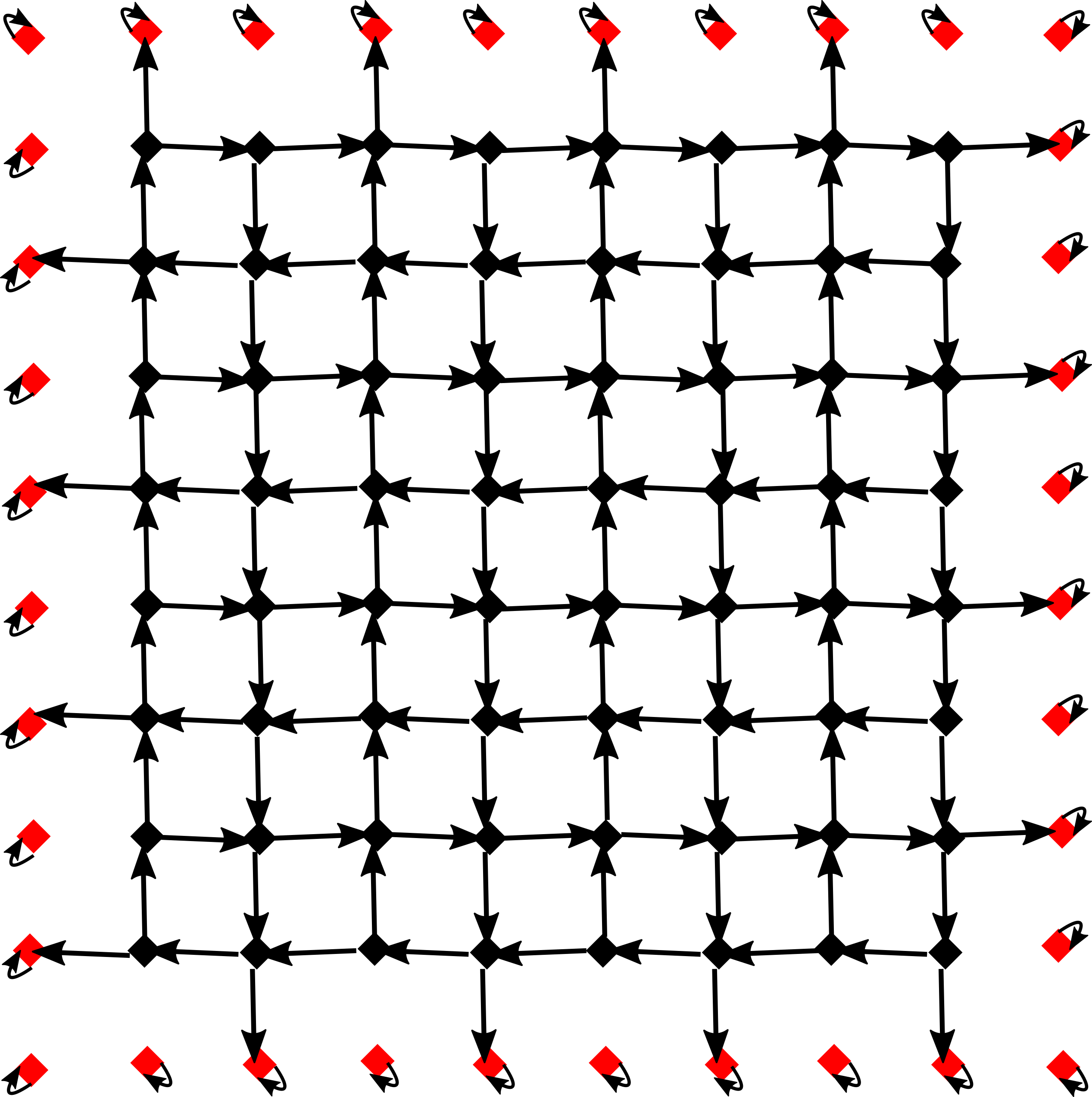
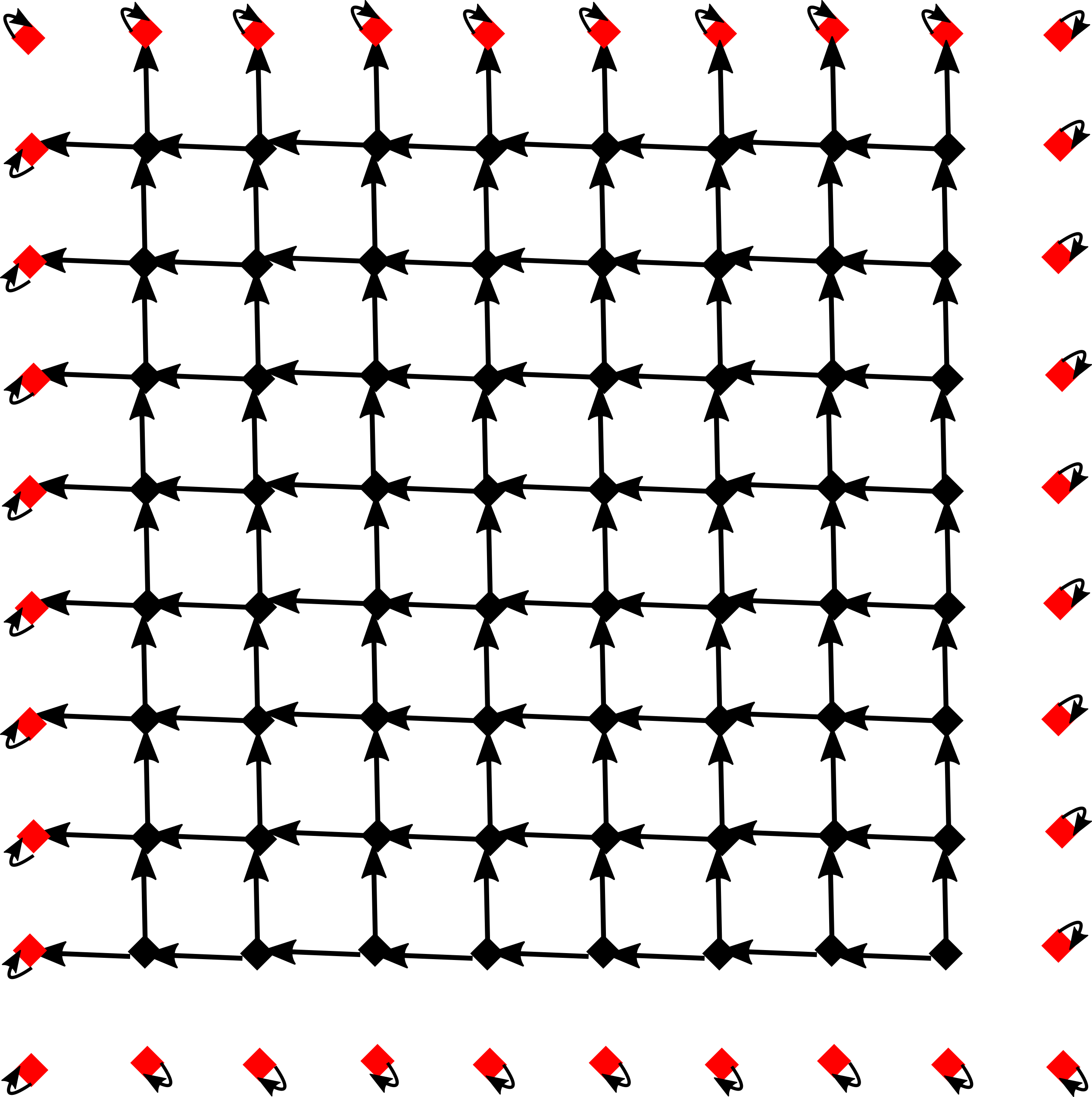
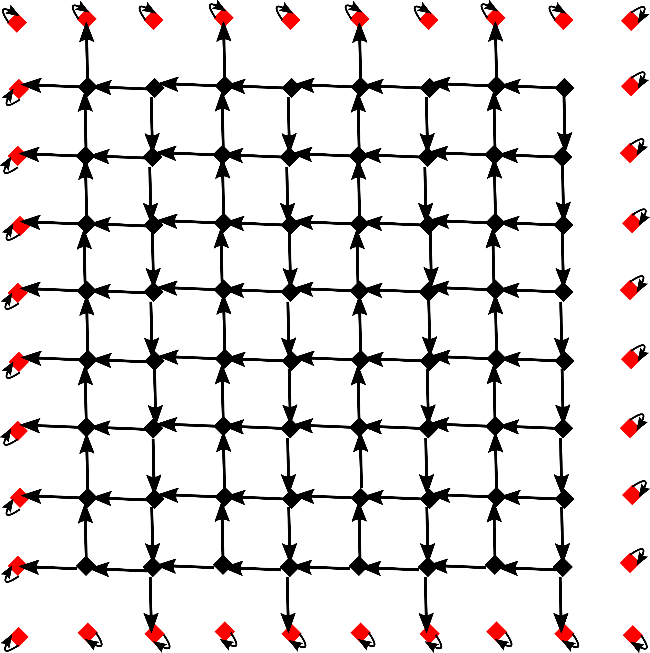
In the context of this paper, we apply a load x𝑥x in the direction d=(0,0,ε)𝑑00𝜀d=(0,0,-\varepsilon) for a small value ε>0𝜀0\varepsilon>0 for each block in the interlocking assembly simultaneously. We use the DGB 𝒢=𝒢(Ap4,d)𝒢𝒢subscript𝐴𝑝4𝑑\mathcal{G}=\mathcal{G}(A_{p4},d) to model how this load is transferred onto the frame of the underlying assembly. This can be achieved by introducing a value function on the arcs of 𝒢𝒢\mathcal{G} yielding a flow network with sinks given by the nodes corresponding to the blocks belonging to the frame. For the assemblies based on the Versatile Block, we give a value function v𝑣v for arcs of the DGB 𝒢𝒢\mathcal{G} as follows: let ij𝑖𝑗i\to j be an arc of 𝒢𝒢\mathcal{G} with i,jI𝑖𝑗𝐼i,j\in I, then we set

v(ij){12,if ij1,if i=j.𝑣𝑖𝑗cases12if 𝑖𝑗1if 𝑖𝑗v(i\to j)\coloneqq\begin{cases}\frac{1}{2},&\text{if }i\neq j\\ 1,&\text{if }i=j.\end{cases}

We choose the value 1212\frac{1}{2} for distinct blocks i,j𝑖𝑗i,j since a given Versatile Block i𝑖i is supported equally by two of its neighbouring blocks. For blocks jJ𝑗𝐽j\in J belonging to the frame, we set v(jj)=1𝑣𝑗𝑗1v(j\to j)=1, since these blocks are stabilised and fixed from moving. We extend the value function v𝑣v to any arcs ij𝑖𝑗i\to j not contained in 𝒢𝒢\mathcal{G} by setting v(ij)=0.𝑣𝑖𝑗0v(i\to j)=0. With this choice of value function v𝑣v it follows that j=1100v(ij)=1superscriptsubscript𝑗1100𝑣𝑖𝑗1\sum_{j=1}^{100}v(i\to j)=1, for all iI𝑖𝐼i\in I and together with the fact that all values of v𝑣v are non-negative, we obtain the (right) stochastic matrix

A=(v(ij))i,jI0100×100,𝐴subscript𝑣𝑖𝑗𝑖𝑗𝐼superscriptsubscriptabsent0100100A=(v(i\to j))_{i,j\in I}\in\mathbb{R}_{\geq 0}^{100\times 100},

i.e. the entries of each row of A𝐴A sum up to 111. This matrix can be viewed as a weighted adjacency matrix of 𝒢𝒢\mathcal{G} yielding a flow network with capacity function v𝑣v. This results in the following combinatorial interpretation of the experiments presented above: let x0I𝑥superscriptsubscriptabsent0𝐼x\in\mathbb{R}_{\geq 0}^{I} be a load vector with xj=0subscript𝑥𝑗0x_{j}=0, if jJ𝑗𝐽j\in J and xi0subscript𝑥𝑖subscriptabsent0x_{i}\in\mathbb{R}_{\geq 0} for iC𝑖𝐶i\in C. Thus the entries of x𝑥x correspond to the applied loads in direction d𝑑d on each block. In the experiments above x𝑥x is chosen to be xi=1subscript𝑥𝑖1x_{i}=1 for iC𝑖𝐶i\in C and xj=0subscript𝑥𝑗0x_{j}=0 for jJ𝑗𝐽j\in J. The model of load transfer can then be discretised by considering the matrix-vector multiplication

Akxsuperscript𝐴𝑘𝑥A^{k}\cdot x

for discrete time steps k=0,,n𝑘0𝑛k=0,\dots,n, where nkmuch-greater-than𝑛𝑘n\gg k is chosen to be large with Anxsuperscript𝐴𝑛𝑥A^{n}\cdot x being close to the convergence load transfer on the frame given the initial load x𝑥x. Since A𝐴A is a stochastic matrix, it follows that the sum over all entries of Akxsuperscript𝐴𝑘𝑥A^{k}\cdot x equals the sum over the entries of x𝑥x, i.e.

i=1100(Akx)i=i=1100xi,superscriptsubscript𝑖1100subscriptsuperscript𝐴𝑘𝑥𝑖superscriptsubscript𝑖1100subscript𝑥𝑖\sum_{i=1}^{100}(A^{k}\cdot x)_{i}=\sum_{i=1}^{100}x_{i},

which can be interpreted as a discrete version of a conservation of energy law. The matrix vector multiplication Akxsuperscript𝐴𝑘𝑥A^{k}\cdot x can be computed by exploiting the flow structure as follows:

  1. 1.

    create an empty square grid corresponding to the Truchet tiling

  2. 2.

    fill the box corresponding iI𝑖𝐼i\in I with the value xisubscript𝑥𝑖x_{i} (initialize vector x𝑥x)

  3. 3.

    add 1/2121/2 times the value of box iC𝑖𝐶i\in C to box j𝑗j if the white part of box i𝑖i touches the black part of box j𝑗j (this corresponds to the matrix multiplication Ax)A\cdot x)

  4. 4.

    iterate the second step k1𝑘1k-1 times with the updated boxes.

Comparison to FEM Analysis

We note that the modelled load transfer onto the frame agrees with the results obtained by the FEM analysis (compare Figure 11 and Figure 13-15). This leads to a fast discrete evaluation criterion which is of interest as there are many assemblies using the Versatile Block. It yields a fast impression of how forces transfer onto the frame. In this way, we can pick candidates for certain applications in a more time-efficient manner. For an 8×8888\times 8 interlocking assembly with 646464 for blocks, there are 28+83=213=8192superscript2883superscript21381922^{8+8-3}=2^{13}=8192 possible assemblies (up to rotation and mirroring) using the Versatile Block, see Akpanya et al. (2023b). For an initial prediction, we can evaluate the force transfer onto the frame for all 819281928192 assemblies in a matter of seconds as it only revolves around matrix-vector multiplications with relatively small quadratic matrices, i.e. 100×100100100100\times 100. This is a major advantage for gaining an initial response as FEM simulations are in general not as cost- and time-efficient. For future research, this discrete evaluation criterion needs to be further investigated and refined to predict how the load transfer from the blocks onto the frame occurs.

6 Discussion

In this work we focused on topological interlocking assemblies consisting of homogeneous and isotropic blocks. We applied assembly strategies based on wallpaper symmetries and used a fixed shape of each block.

6.1 Future work

Influence of geometric properties

The authors of Akpanya et al. (2023b) have shown that there are exponentially many possibilities to arrange the Versatile Block into a topological interlocking assembly. Investigating several assemblies which do not admit a wallpaper symmetry might extend the understanding of the influence of arrangement on the mechanical performance of topological interlocking assemblies.

The blocks investigated in this paper were created using wallpaper groups. Using the techniques in Goertzen et al. (2022) it is possible to create many different blocks and the influence of the choice of block on the mechanical performance can be investigated.

It is well known that a structure under load experiences stress spikes in its corners. It needs to be investigated if the design of the block can be modified to reduce these spikes.

Another factor influencing the performance of the topological interlocking assembly might be the distance between the top and bottom plane of the planar assembly. In order to design material minimised components the mechanical performance of relatively thin assemblies should be investigated.

Influence of mechanical properties

In the simulations discussed here friction has been ignored to isolate the effect the arrangement has on the mechanical performance. Moreover, the force has always been applied to the top plane. In general, the impact of friction and applying the load to the bottom plane should be investigated.

To gain an insight into how the assembly reacts to loads in general, the load is applied evenly to all rectangles (each consisting of three triangular faces) on the top plane. However, in certain applications of such an assembly, the loads could be more localised. To understand how the assembly reacts to more localised loads and especially how the stresses are transferred throughout the assembly, additional simulations are required. Gaining an insight into this stress distribution could also guide the placement and choice of reinforcement inside each block.

One of the main goals of using reinforced materials is to design resource-efficient and lightweight components. Therefore, it is paramount to test whether interlocking assemblies constructed by removing the interior of all blocks display a similar performance properties to assemblies constructed of solid blocks. Note that the interior of hollow blocks could be filled with a different material to influence other properties, e.g. by inserting insulating material, sound proofing material or using the space for electrical wiring.

6.2 Conclusion

The arrangement of the blocks in topological interlocking assemblies has a significant influence on the structural behaviour of the overall assembly such as its point of deflection, the load transfer mechanisms, as well as stress distribution. We investigated three different symmetric arrangements of the Versatile Block and showcased these differences in mechanical behaviour by FEM analyses. Moreover, by comparison with a monolithic plate we demonstrated that the structural behaviour of TIA is qualitatively and quantitatively in the same order of magnitude. Further, we developed a combinatorial tool that is capable of pre-evaluating the load transfer onto the frame. In summary we showed that by exploiting the rich combinatorial theory of the Versatile Block we obtain several interlocking assemblies with key differences. The question arises whether there is a possibility to take advantage of the differences to custom-tailor interlocking assemblies for particular applications.

Contributor Roles

Tom Goertzen developed the Versatile Block, wrote code, reviewed the relevant existing literature and wrote a part of this article. Domen Macek planned and performed FEM analyses, validated the numerical results and wrote a part of this article. Lukas Schnelle wrote code, planned and performed FEM analyses and wrote a part of this article. Meike Weiß planned FEM analyses and wrote part of this article. Stefanie Reese: acquired funding. Hagen Holthusen acquired funding, gave conceptual advice, contributed in the discussion of the results, read the article and gave valuable suggestions for improvement. Alice C. Niemeyer wrote part of this article, acquired funding, gave conceptual advice and supervised.

Acknowledgements

The authors gratefully acknowledge funding by the Deutsche Forschungsgemeinschaft (DFG, German Research Foundation) in the framework of the Collaborative Research Centre CRC/TRR 280 “Design Strategies for Material-Minimized Carbon Reinforced Concrete Structures – Principles of a New Approach to Construction” (project ID 417002380). The authors also thank Max Horn and Katharina Martin for their very valuable comments and advice.

References

  • Akleman et al. (2020) Ergun Akleman, Vinayak R. Krishnamurthy, Chia-An Fu, Sai Ganesh Subramanian, Matthew Ebert, Matthew Eng, Courtney Starrett, and Haard Panchal. Generalized abeille tiles: Topologically interlocked space-filling shapes generated based on fabric symmetries. Computers & Graphics, 89:156–166, 2020. ISSN 0097-8493. doi: https://doi.org/10.1016/j.cag.2020.05.016. URL https://www.sciencedirect.com/science/article/pii/S0097849320300674.
  • Akpanya et al. (2023a) Reymond Akpanya, Tom Goertzen, and Alice C. Niemeyer. A group-theoretic approach for constructing spherical-interlocking assemblies. In Y.M. Xie, J. Burry, T.U. Lee, and J. Ma, editors, Proceedings of the IASS Annual Symposium 2023: Integration of Design and Fabrication, pages 470–480, Melbourne, Australia, 7 2023a. International Association for Shell and Spatial Structures (IASS).
  • Akpanya et al. (2023b) Reymond Akpanya, Tom Goertzen, Sebastian Wiesenhuetter, Alice C. Niemeyer, and Jörg Noennig. Topological interlocking, truchet tiles and self-assemblies: A construction-kit for civil engineering design. In Judy Holdener, Eve Torrence, Chamberlain Fong, and Katherine Seaton, editors, Proceedings of Bridges 2023: Mathematics, Art, Music, Architecture, Culture, pages 61–68, Phoenix, Arizona, 2023b. Tessellations Publishing. ISBN 978-1-938664-45-8. URL http://archive.bridgesmathart.org/2023/bridges2023-61.html.
  • Armstrong (1988) M. A. Armstrong. Groups and symmetry. Undergraduate Texts in Mathematics. Springer-Verlag, New York, 1988. ISBN 0-387-96675-7. doi: 10.1007/978-1-4757-4034-9. URL https://doi.org/10.1007/978-1-4757-4034-9.
  • Aroyo (December 2016) Mois I. Aroyo, editor. International Tables for Crystallography, Volume A: Space-group symmetry, volume A. Wiley, 6th edition, December 2016. ISBN: 978-0-470-97423-0, https://doi.org/10.1107/97809553602060000114.
  • Dugué et al. (2013) M. Dugué, M. Fivel, Y. Bréchet, and R. Dendievel. Indentation of interlocked assemblies: 3D discrete simulations and experiments. Computational Materials Science, 79:591–598, 2013. ISSN 0927-0256. doi: https://doi.org/10.1016/j.commatsci.2013.07.014. URL https://www.sciencedirect.com/science/article/pii/S0927025613004151.
  • Dyskin et al. (2001a) A. V. Dyskin, Y. Estrin, A. J. Kanel-Belov, and E. Pasternak. A new concept in design of materials and structures: assemblies of interlocked tetrahedron-shaped elements. Scripta Materialia, 44(12):2689–2694, 2001a. ISSN 1359-6462. doi: https://doi.org/10.1016/S1359-6462(01)00968-X. URL https://www.sciencedirect.com/science/article/pii/S135964620100968X.
  • Dyskin et al. (2001b) A. V. Dyskin, Y. Estrin, A. J. Kanel-Belov, and E. Pasternak. Toughening by Fragmentation—How Topology Helps. Advanced Engineering Materials, 3(11):885–888, 2001b. doi: https://doi.org/10.1002/1527-2648(200111)3:11¡885::AID-ADEM885¿3.0.CO;2-P. URL https://onlinelibrary.wiley.com/doi/abs/10.1002/1527-2648%28200111%293%3A11%3C885%3A%3AAID-ADEM885%3E3.0.CO%3B2-P. _eprint: https://onlinelibrary.wiley.com/doi/pdf/10.1002/1527-2648%28200111%293%3A11%3C885%3A%3AAID-ADEM885%3E3.0.CO%3B2-P.
  • Dyskin et al. (2003a) A. V. Dyskin, Y. Estrin, A. J. Kanel-Belov, and E. Pasternak. Topological interlocking of platonic solids: A way to new materials and structures. Philosophical Magazine Letters, 83(3):197–203, January 2003a. ISSN 0950-0839. doi: 10.1080/0950083031000065226. URL https://doi.org/10.1080/0950083031000065226. Publisher: Taylor & Francis.
  • Dyskin et al. (2019) A. V. Dyskin, Yuri Estrin, and E. Pasternak. Topological Interlocking Materials. In Yuri Estrin, Yves Bréchet, John Dunlop, and Peter Fratzl, editors, Architectured Materials in Nature and Engineering: Archimats, pages 23–49. Springer International Publishing, Cham, 2019. ISBN 978-3-030-11942-3. doi: 10.1007/978-3-030-11942-3˙2. URL https://doi.org/10.1007/978-3-030-11942-3_2.
  • Dyskin et al. (2003b) A.V. Dyskin, Y. Estrin, E. Pasternak, H.C. Khor, and A.J. Kanel-Belov. Fracture Resistant Structures Based on Topological Interlocking with Non-planar Contacts. Advanced Engineering Materials, 5(3):116–119, March 2003b. ISSN 1438-1656. doi: 10.1002/adem.200390016. URL https://doi.org/10.1002/adem.200390016. Publisher: John Wiley & Sons, Ltd.
  • Ebert et al. (2023) Matthew Ebert, Ergun Akleman, Vinayak Krishnamurthy, Roman Kulagin, and Yuri Estrin. VoroNoodles: Topological Interlocking with Helical Layered 2-Honeycombs. Advanced Engineering Materials, n/a(n/a):2300831, October 2023. ISSN 1438-1656. doi: 10.1002/adem.202300831. URL https://doi.org/10.1002/adem.202300831. Publisher: John Wiley & Sons, Ltd.
  • Estrin et al. (2021) Yuri Estrin, Vinayak R. Krishnamurthy, and Ergun Akleman. Design of architectured materials based on topological and geometrical interlocking. Journal of Materials Research and Technology, 15:1165–1178, 2021. ISSN 2238-7854. doi: https://doi.org/10.1016/j.jmrt.2021.08.064. URL https://www.sciencedirect.com/science/article/pii/S2238785421008899.
  • Feldfogel et al. (2023) Shai Feldfogel, Konstantinos Karapiperis, Jose Andrade, and David S. Kammer. Scaling, saturation, and upper bounds in the failure of topologically interlocked structures. International Journal of Solids and Structures, 269:112228, 2023. ISSN 0020-7683. doi: https://doi.org/10.1016/j.ijsolstr.2023.112228. URL https://www.sciencedirect.com/science/article/pii/S0020768323001257.
  • Feldfogel et al. (2024) Shai Feldfogel, Konstantinos Karapiperis, Jose Andrade, and David S. Kammer. Failure of topologically interlocked structures — a Level-Set-DEM approach. European Journal of Mechanics - A/Solids, 103:105156, 2024. ISSN 0997-7538. doi: https://doi.org/10.1016/j.euromechsol.2023.105156. URL https://www.sciencedirect.com/science/article/pii/S0997753823002486.
  • Feng et al. (2015) Yuezhong Feng, Thomas Siegmund, Ed Habtour, and Jaret Riddick. Impact mechanics of topologically interlocked material assemblies. International Journal of Impact Engineering, 75:140–149, 2015. ISSN 0734-743X. doi: https://doi.org/10.1016/j.ijimpeng.2014.08.003. URL https://www.sciencedirect.com/science/article/pii/S0734743X14001821.
  • Frézier (1738) Amédée François Frézier. La theorie et la pratique de la coupe des pierres et des bois, pour la construction des voutes et autres parties des bâtimens civils & militaires, ou Traité de stereotomie a l’usage de l’architecture, volume 2. Doulsseker, 1738.
  • Gallon (1735) J.-G. Gallon. Machines et inventions approuvées par l’Académie Royale des Sciences depuis son établissement jusqu’à present; avec leur Description. Académie royale des Sciences, 1735.
  • (19) GAP. GAP – Groups, Algorithms, and Programming, Version 4.12.2. https://www.gap-system.org, Dec 18.
  • Glickman (1984) Michael Glickman. The G-block system of vertically interlocking paving. In Second International Conference on Concrete Block Paving, pages 10–12, 1984.
  • Goertzen et al. (2022) Tom Goertzen, Alice C. Niemeyer, and Wilhelm Plesken. Topological interlocking via symmetry. In S. Stokkeland and H.C Braarud, editors, 6th fib International Congress on Concrete Innovation for Sustainability, 2022; Oslo; Norway, pages 1235–1244, 2022. URL https://www.scopus.com/inward/record.uri?eid=2-s2.0-85143905977&partnerID=40&md5=157f82e57ed12d582902da55864644a7.
  • Goertzen et al. (2023) Tom Goertzen, Domen Macek, Lukas Schnelle, Meike Weiß, Stefanie Reese, Hagen Holthusen, and Alice C. Niemeyer. Mechanical Comparison of Arrangement Strategies for Topological Interlocking Assemblies: Abaqus input files, December 2023. URL https://doi.org/10.5281/zenodo.10246034.
  • Kanel-Belov et al. (2010) A. J. Kanel-Belov, A. V. Dyskin, Y. Estrin, E. Pasternak, and I. A. Ivanov-Pogodaev. Interlocking of convex polyhedra: towards a geometric theory of fragmented solids. Mosc. Math. J., 10(2):337–342, 478–479, 2010. ISSN 1609-3321,1609-4514. doi: 10.17323/1609-4514-2010-10-2-337-342. URL https://doi.org/10.17323/1609-4514-2010-10-2-337-342.
  • Kim and Siegmund (2021) Dong Young Kim and Thomas Siegmund. Mechanics and design of topologically interlocked irregular quadrilateral tessellations. Materials & Design, 212:110155, 2021. ISSN 0264-1275. doi: https://doi.org/10.1016/j.matdes.2021.110155. URL https://www.sciencedirect.com/science/article/pii/S0264127521007103.
  • Koureas et al. (2022) Ioannis Koureas, Mohit Pundir, Shai Feldfogel, and David S. Kammer. On the failure of beam-like topologically interlocked structures. International Journal of Solids and Structures, 259:112029, 2022. ISSN 0020-7683. doi: https://doi.org/10.1016/j.ijsolstr.2022.112029. URL https://www.sciencedirect.com/science/article/pii/S0020768322004826.
  • Koureas et al. (2023) Ioannis Koureas, Mohit Pundir, Shai Feldfogel, and David S. Kammer. Beam-Like Topologically Interlocked Structures With Hierarchical Interlocking. Journal of Applied Mechanics, 90(081008), May 2023. ISSN 0021-8936. doi: 10.1115/1.4062348. URL https://doi.org/10.1115/1.4062348.
  • Krause et al. (2012) T. Krause, A. Molotnikov, M. Carlesso, J. Rente, K. Rezwan, Y. Estrin, and D. Koch. Mechanical Properties of Topologically Interlocked Structures with Elements Produced by Freeze Gelation of Ceramic Slurries. Advanced Engineering Materials, 14(5):335–341, 2012. doi: https://doi.org/10.1002/adem.201100244. URL https://onlinelibrary.wiley.com/doi/abs/10.1002/adem.201100244. _eprint: https://onlinelibrary.wiley.com/doi/pdf/10.1002/adem.201100244.
  • Laursen (2002) Tod A. Laursen. Computational Contact and Impact Mechanics. Springer Berlin, Heidelberg, 2002. doi: 10.1007/978-3-662-04864-1.
  • Mirkhalaf et al. (2018) Mohammad Mirkhalaf, Tao Zhou, and Francois Barthelat. Simultaneous improvements of strength and toughness in topologically interlocked ceramics. Proceedings of the National Academy of Sciences, 115(37):9128–9133, 2018. doi: 10.1073/pnas.1807272115. URL https://www.pnas.org/doi/abs/10.1073/pnas.1807272115. _eprint: https://www.pnas.org/doi/pdf/10.1073/pnas.1807272115.
  • Mullins et al. (2022) Cassie Mullins, Matthew Ebert, Ergun Akleman, and Vinayak Krishnamurthy. Voronoi Spaghetti & VoroNoodles: Topologically Interlocked, Space-Filling, Corrugated & Congruent Tiles. In SIGGRAPH Asia 2022 Technical Communications, SA ’22, New York, NY, USA, 2022. Association for Computing Machinery. ISBN 978-1-4503-9465-9. doi: 10.1145/3550340.3564229. URL https://doi.org/10.1145/3550340.3564229. event-place: Daegu, Republic of Korea.
  • Niemeyer et al. (2021) A.C. Niemeyer, M. Baumeister, R. Akpanya, T. Görtzen, M. Weiß, and T. GAP Team. SimplicialSurfaces, computing with simplicial surfaces and folding processes., Version 0.6. https://github.com/gap-packages/SimplicialSurfaces, 09 2021. GAP package.
  • Rezaee Javan et al. (2017) A. Rezaee Javan, H. Seifi, S. Xu, D. Ruan, and Y.M. Xie. The impact behaviour of plate-like assemblies made of new interlocking bricks: An experimental study. Materials & Design, 134:361–373, 2017. ISSN 0264-1275. doi: https://doi.org/10.1016/j.matdes.2017.08.056. URL https://www.sciencedirect.com/science/article/pii/S0264127517308146.
  • Rezaee Javan et al. (2018) A. Rezaee Javan, H. Seifi, S. Xu, X. Lin, and Y. M. Xie. Impact behaviour of plate-like assemblies made of new and existing interlocking bricks: A comparative study. International Journal of Impact Engineering, 116:79–93, 2018. ISSN 0734-743X. doi: https://doi.org/10.1016/j.ijimpeng.2018.02.008. URL https://www.sciencedirect.com/science/article/pii/S0734743X18300484.
  • Rezaee Javan et al. (2016) Anooshe Rezaee Javan, Hamed Seifi, Shanqing Xu, and Yi Min Xie. Design of a new type of interlocking brick and evaluation of its dynamic performance. In Proceedings of IASS Annual Symposia, IASS 2016 Tokyo Symposium: Spatial Structures in the 21st Century – New Approaches, Materials & Construction Methods, pages 1–8, Tokyo, Japan, September 26 2016. International Association for Shell and Spatial Structures (IASS), International Association for Shell and Spatial Structures (IASS).
  • Rezaee Javan et al. (2020) Anooshe Rezaee Javan, Hamed Seifi, Xiaoshan Lin, and Yi Min Xie. Mechanical behaviour of composite structures made of topologically interlocking concrete bricks with soft interfaces. Materials & Design, 186:108347, 2020. ISSN 0264-1275. doi: https://doi.org/10.1016/j.matdes.2019.108347. URL https://www.sciencedirect.com/science/article/pii/S0264127519307853.
  • Schaare et al. (2008) S. Schaare, A. V. Dyskin, Y. Estrin, S. Arndt, E. Pasternak, and A. Kanel-Belov. Point loading of assemblies of interlocked cube-shaped elements. International Journal of Engineering Science, 46(12):1228–1238, 2008. ISSN 0020-7225. doi: https://doi.org/10.1016/j.ijengsci.2008.06.012. URL https://www.sciencedirect.com/science/article/pii/S0020722508001079.
  • Schaare et al. (2009) Stephan Schaare, Werner Riehemann, and Yuri Estrin. Damping properties of an assembly of topologically interlocked cubes. Materials Science and Engineering: A, 521-522:380–383, 2009. ISSN 0921-5093. doi: https://doi.org/10.1016/j.msea.2008.10.069. URL https://www.sciencedirect.com/science/article/pii/S0921509309002342.
  • Short and Siegmund (2019) M. Short and T. Siegmund. Scaling, Growth, and Size Effects on the Mechanical Behavior of a Topologically Interlocking Material Based on Tetrahedra Elements. Journal of Applied Mechanics, 86(111007), September 2019. ISSN 0021-8936. doi: 10.1115/1.4044025. URL https://doi.org/10.1115/1.4044025.
  • Subramanian et al. (2019) Sai Ganesh Subramanian, Mathew Eng, Vinayak R. Krishnamurthy, and Ergun Akleman. Delaunay Lofts: A biologically inspired approach for modeling space filling modular structures. Computers & Graphics, 82:73–83, 2019. ISSN 0097-8493. doi: https://doi.org/10.1016/j.cag.2019.05.021. URL https://www.sciencedirect.com/science/article/pii/S0097849319300822.
  • Szczepański (2012) Andrzej Szczepański. Geometry of crystallographic groups, volume 4 of Algebra and Discrete Mathematics. World Scientific Publishing Co. Pte. Ltd., Hackensack, NJ, 2012. ISBN 978-981-4412-25-4. doi: 10.1142/8519. URL https://doi.org/10.1142/8519.
  • Ullmann et al. (2023) Silvan Ullmann, David S. Kammer, and Shai Feldfogel. The Deflection Limit of Slab-Like Topologically Interlocked Structures. Journal of Applied Mechanics, 91(021004), October 2023. ISSN 0021-8936. doi: 10.1115/1.4063345. URL https://doi.org/10.1115/1.4063345.
  • Wang et al. (2018) Ziqi Wang, Peng Song, and Mark Pauly. DESIA: A General Framework for Designing Interlocking Assemblies. ACM Trans. Graph., 37(6), December 2018. ISSN 0730-0301. doi: 10.1145/3272127.3275034. URL https://doi.org/10.1145/3272127.3275034. Place: New York, NY, USA Publisher: Association for Computing Machinery.
  • Weizmann et al. (2021) Michael Weizmann, Oded Amir, and Yasha Jacob Grobman. The effect of block geometry on structural behavior of topological interlocking assemblies. Automation in Construction, 128:103717, 2021. ISSN 0926-5805. doi: https://doi.org/10.1016/j.autcon.2021.103717. URL https://www.sciencedirect.com/science/article/pii/S0926580521001680.
  • Williams and Siegmund (2021) Andrew Williams and Thomas Siegmund. Mechanics of topologically interlocked material systems under point load: Archimedean and Laves tiling. International Journal of Mechanical Sciences, 190:106016, 2021. ISSN 0020-7403. doi: https://doi.org/10.1016/j.ijmecsci.2020.106016. URL https://www.sciencedirect.com/science/article/pii/S0020740320315290.
  • Wilson (1992) Randall H. Wilson. On Geometric Assembly Planning. PhD thesis, Stanford, CA, USA, 1992. UMI Order No. GAX92-21686.
  • Wilson and Latombe (1994) Randall H. Wilson and Jean-Claude Latombe. Geometric reasoning about mechanical assembly. Artificial Intelligence, 71(2):371–396, 1994. ISSN 0004-3702. doi: https://doi.org/10.1016/0004-3702(94)90048-5. URL https://www.sciencedirect.com/science/article/pii/0004370294900485.
  • Wriggers (2006) Peter Wriggers. Computational Contact Mechanics. Springer Berlin, Heidelberg, 2006. doi: 10.1007/978-3-540-32609-0.
  • Wriggers (2008) Peter Wriggers. Nonlinear Finite Element Methods. Springer Berlin, Heidelberg, 2008. doi: 10.1007/978-3-540-71001-1.
  • Yong (2011) Hsien Ta David Yong. Utilisation of topologically-interlocking osteomorphic blocks for multi-purpose civil construction. Doctoral Thesis, 2011.
  • Zienkiewicz et al. (2005) Olek C Zienkiewicz, Robert L. Taylor, and Jian Z. Zhu. The Finite Element Method: Its Basis and Fundamentals. Elsevier, 2005.

Appendix A Software usage

The interlocking assemblies are generated using the SimplicialSurfaces Package Niemeyer et al. (2021) for GAP GAP . In this, we generate the different assemblies by first defining and rotating a single Versatile block to all four orientations that can occur in a planar assembly. Then we create the assemblies given by the wallpaper groups of the three interlockings as described in 3.4.
Here we divide the assembly into the outermost perimeter of blocks that we use as the frame. In the following the remaining part will be referred to as the core.
These assemblies are then exported as individual .stl files, which after a second conversion to .step files can be imported as geometries into abaqus. This is done individually to allow easier applying of the boundary conditions but has no effect on the geometry as a whole. We use a 10×10101010\times 10 grid of 100100100 blocks in each of the periodic interlockings. This is done to have an as similar as possible size of interlocking to compare.

Note: The simulations where run with a scaling factor to the coordinates above to fit existing concrete blocks and make it comparable. The scaling was 0.420.42\frac{0.4}{\sqrt{2}} in x𝑥x and y𝑦y direction as well as 1515\frac{1}{5} in z𝑧z direction.