Feedback Cooling of an Insulating High-Q Diamagnetically Levitated Plate
Abstract
Levitated systems in vacuum have many potential applications ranging from new types of inertial and magnetic sensors through to fundamental issues in quantum science, the generation of massive cats, and the connections between gravity and quantum physics. In this work, we demonstrate the passive, diamagnetic levitation of a centimeter-sized massive oscillator which is fabricated using a novel method that ensures that the material, though highly diamagnetic, is an electrical insulator. By chemically coating a powder of microscopic graphite beads with silica and embedding the coated powder in high-vacuum compatible wax, we form a centimeter-sized thin square plate which magnetically levitates over a checkerboard magnet array. The insulating coating reduces eddy damping by almost an order of magnitude compared to uncoated graphite with the same particle size. These plates exhibit a different equilibrium orientation to pyrolytic graphite due to their isotropic magnetic susceptibility. We measure the motional quality factor to be for an approximately centimeter-sized composite resonator with a mean particle size of 12 microns. Further, we apply delayed feedback to cool the vertical motion of frequency from room temperature to 320 millikelvin.
Optomechanical systems are the most precise measuring devices in existence, most notably the LIGO gravitational wave observatory which can measure distortions in spacetime 10,000 smaller than a proton. Tabletop systems aim to exploit the versatile optomechanical interaction to design compact quantum sensors. Optomechanical systems are fundamentally limited by thermal noise from the environment, which interferes with the measurement signal and causes decoherence of fragile quantum states. Levitated optomechanics suspends the system without any physical connection to the environment. The resulting exquisite isolation means that the quantum ground state can be attained at room temperature using feedback-cooling.[1, 2] This is promising for both high-precision laboratory measurements, and deployment in noisy real-world settings.[3, 4] Levitation also leads to a natural coupling with gravity. Thus levitated systems are natural testbeds for probing some of the deepest outstanding questions in physics, such as quantum gravity and collapse mechanisms.[5]
Diamagnetic levitation of graphite slabs has been gaining increasing attention as a platform for levitated optomechanics. Most levitated platforms use active methods such as optical tweezers or Paul traps. These use time-varying optical or electromagnetic fields,[3, 4] and can trap particles of nano- and micro-meter sizes. In contrast diamagnetic levitation is passive, and centimeter-sized slabs of graphite can be easily levitated above an array of commercially-available permanent magnets.[6, 7, 8, 9, 10] This removes the noise associated with an active power source.[11] Moreover, the lowered power and hardware requirements are promising for developing commercial sensors. Diamagnetic levitation can also support much larger masses than traditional levitated optomechanics. More massive systems have greater sensitivity for accelerometry and gravimetry,[12] and are crucial to explore the behaviour of quantum physics at larger scales. The large mass, ease of use, and passive nature give graphite diamagnetic levitation a unique status in levitated optomechanics.
The greatest limiting factor for these systems is eddy damping. Most experiments use Highly Oriented Pyrolytic Graphite (HOPG), a synthetic material consisting of layered planes of graphite. This has a very strong diamagnetic susceptibility along the axis perpendicular to the graphite planes. However, HOPG is an electrical conductor. As it moves through the magnetic field generated by the magnets, currents are induced along the graphite planes, which causes strong damping. Consequently the quality factor of levitated pyrolytic graphite in vacuum is only several hundred for millimeter-sized slabs, and decreases as size increases.[10] Although a thin graphite film has demonstrated sufficient sensitivity to experimentally test theories of dark matter,[13] increasing the quality factor would substantially increase sensitivity, and unlock powerful feedback-cooling methods.
It is thus necessary to find methods of suppressing eddy damping in levitated graphite systems. The currents can be disrupted by engineering narrow slits, allowing quality factors of several thousand in vacuum.[14, 15] An alternative approach has been to use composite materials, consisting of micrometer-sized graphite particles dispersed in an insulating resin.[16] Eddy currents can only flow within the microparticles, or between neighbouring particles which happen to touch. Millimeter-sized slabs of this composite graphite attained quality factors of half a million at high vacuum at room temperature, the largest demonstrated for any system of that mass.[16]
Composite graphite is thus a highly promising system for levitated optomechanics. However, it also presents new challenges. Since the magnetic susceptibility of graphite is highly oriented, the random positioning of particles in the composite lowers the effective magnetic susceptibility. The susceptibility further decreases for particle sizes smaller than ,[17] though such sizes are necessary to significantly suppress eddy currents. Thus the mass that can be supported is decreased, if for example we wished to place a mirror or other system on the levitated graphite. There is also a limit on the volume fraction of graphite in the material, which was about in Chen et al[16] for reasons of structural integrity. Moreover, the graphite particles must be kept separated by the insulating resin. At high volume fractions it becomes increasingly likely that neighbouring graphite particles will touch, allowing eddy currents to flow between them and thus decreasing the quality factor.
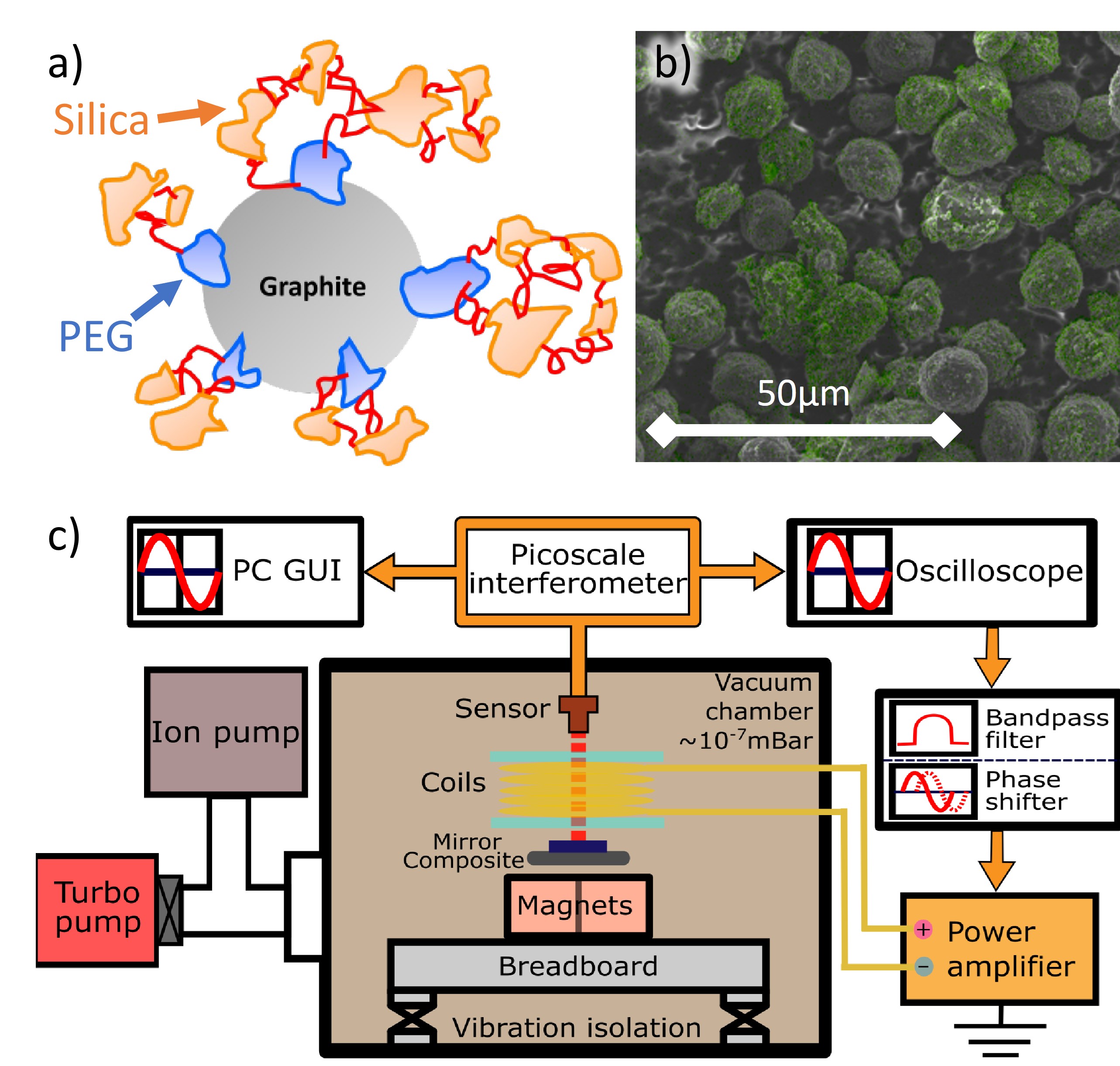
To enable large graphite volume fractions while maintaining suppression of eddy currents, we coat the graphite particles with an insulating shell. Our graphite particles are mesocarbon microbeads (MCMB), whose average diameter is . We chemically coat these with a thin insulating layer of silica in a ‘sol-gel process’ using polyethylene glycol (PEG) and the silica precursor tetraethyl orthosilicate (TEOS),[18] see the supplementary material for details on the fabrication process. First PEG adsorbs onto the surface of the microcarbon microbeads. A solution of TEOS and ammonium hydroxide catalyst is then added, and stirred for 17 hours on a hot plate. During this time silicon from TEOS attaches to the PEG, resulting in a silica coating on the graphite as shown in Fig. 1 a). The mixture is then washed, filtered, and dried. Analysis using scanning electron microscopy with elemental mapping shown in Fig. 1 b) confirms the near-uniform coverage of the graphite beads with silica. The powder is then mixed in vacuum-compatible wax at a temperature of approximately , then cooled and shaped into small square slabs of approximate width and thickness . The mass fraction of graphite is , with the volume fraction estimated as . At fractions larger than this mixing the graphite powder into the wax requires significant stirring force, which causes cracking of the silica shell.
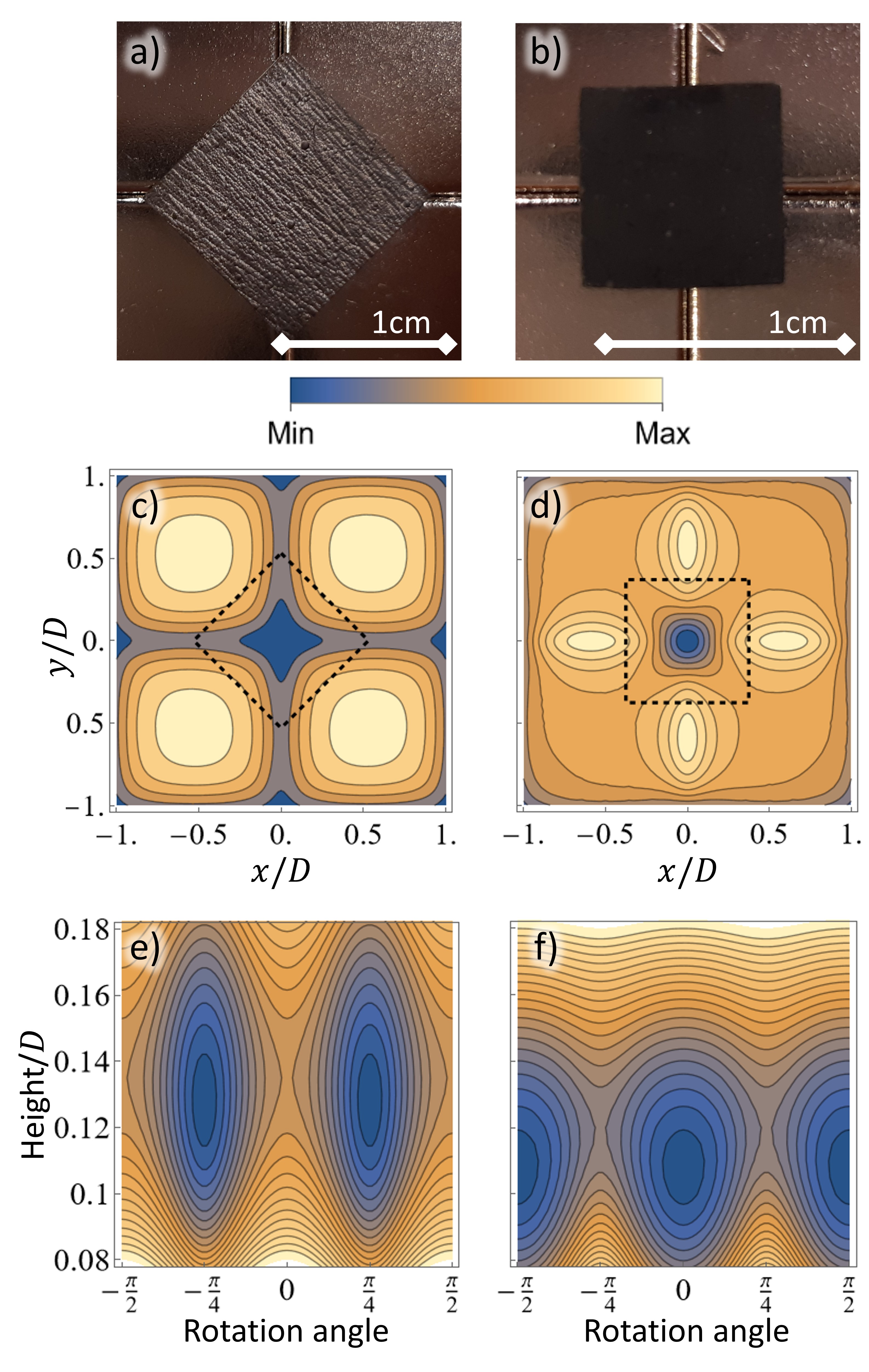
The graphite slabs are levitated above a checkerboard-array of four permanent magnets, whose upper faces alternate between north and south poles. In Fig. 2 a) and b) we show photographs of both pyrolytic and composite graphite, taken from above once their position had reached equilibrium. We can see that the pyrolytic and composite graphite exhibit different orientations. This arises from the difference in their magnetic susceptibilities. The potential energy of a diamagnet in a magnetic field is given by
| (1) |
Here are the components of the magnetic susceptibility tensor, the components of the magnetic field, and is the vacuum permeability. The integral is over the volume of the slab, which depends on its levitation height and rotation . The susceptibility of Pyrolytic graphite is highly oriented: , and thus it orients itself primarily to avoid the -component of the magnetic field. The composite graphite on the other hand has uniform susceptibility[16] , and orients itself to avoid all magnetic field components equally. We plot the magnetic potential energy densities in Fig. 2 c) and d), which we see accounts for the difference in orientation.
We further study the difference between the two materials by evaluating the total potential energy, which is the sum of the magnetic and gravitational components. See the Supplementary for details of this calculation. We graph this for pyrolytic and composite graphite in Fig. 2 e) and f), which clearly show the difference in orientation. We can see that the composite graphite experiences a much looser angular confinement. The composite also levitates lower. There are several effects which contribute to the different levitation height, namely the lower effective susceptibility of the composite, its graphite mass fraction of 60%, and the density of the wax. These factors also influence the shape of the trap, as we discuss in the Supplementary material.
We note that these observations seem to disagree with those of Chen et al. 2022,[16] which reported composite resonators to orient themselves similarly to pyrolytic graphite. A more detailed analysis in our Supplementary material does not find a regime where such orientation is expected. One likely explanation is the geometry of the magnets. In our experiment shown in Fig. 2 a-b) the chamfering is small compared to the size of the magnets and graphite slabs, hence we assumed the magnets to be perfect cubes in our analysis. However, in Chen et. al Figure 1d the magnets show significant chamfering, comparable to the size of their composite slabs. Given how shallow the composite potential is in Fig. 2 f), it is likely that this could be distorted by such changes to the magnet geometry. Another explanation could be that some unknown factor is causing slight orientation of the particles in their composite.
The composite’s trapped dynamics was characterised using the setup shown in Fig. 1 c). The graphite levitates above a checkerboard of four permanent magnets, with a small mirror placed on top of the slab in order to read out its position and velocity with a Picoscale interferometer. This setup is most sensitive to the slab’s vertical oscillation, which has a frequency of . We actuate the system using a coil situated just above the graphite. A current flowing through this coil generates a magnetic field along its vertical axis, which perturbs the field generated by the magnets and thus exerts a force on the graphite. As discussed in the supplementary material, the force exerted by the coil depends only on the magnitude of the applied voltage, not its sign. When applying voltage signals to the coil, we thus operate around a DC shift, allowing us to apply both positive and negative forces. When performing measurement at high vacuum only the ion pump is left on, allowing us to maintain vacuum while minimising vibrations. We refer to the supplementary material for further details on the setup.
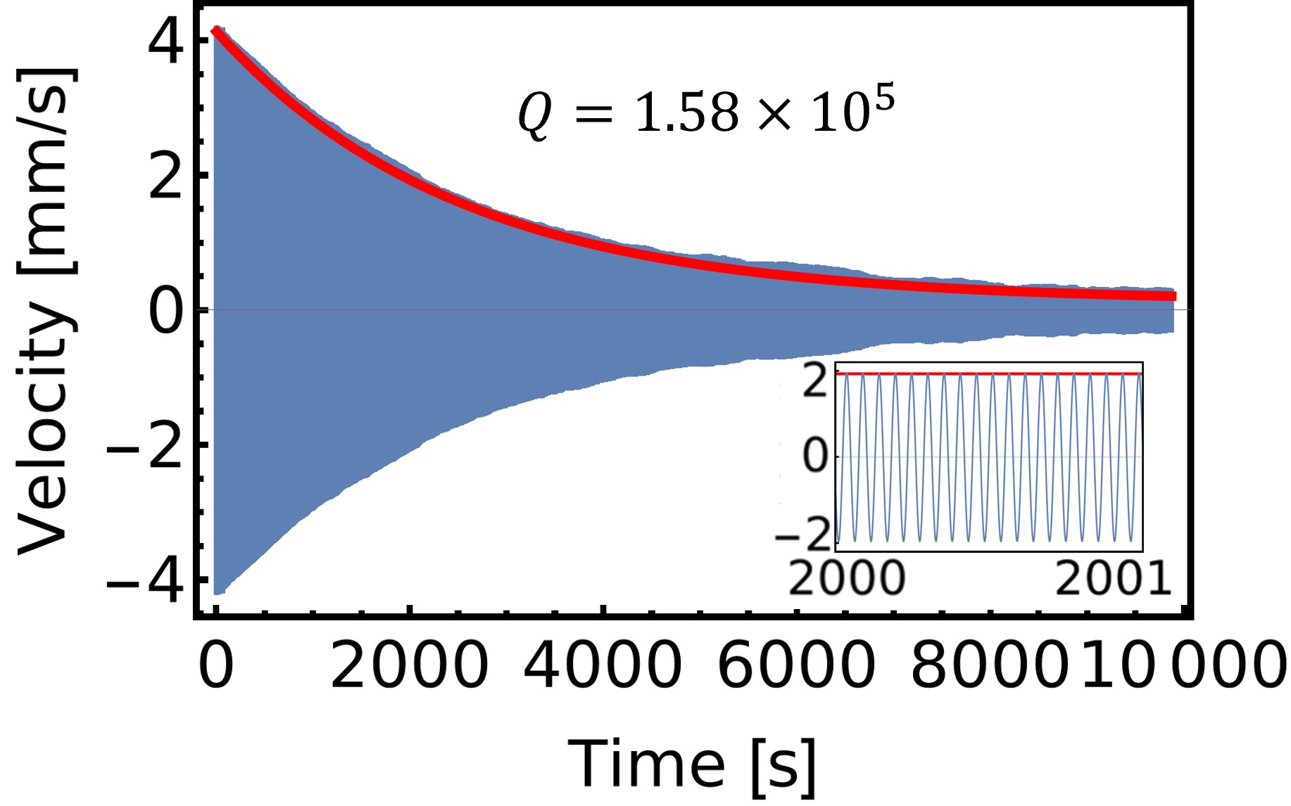
To study the eddy damping in our novel composite, we drive the vertical mode using the coil at the resonance frequency of , and then measure the ringdown at a pressure of for , as shown in Fig. 3. The velocity of a damped resonator decays exponentially as , where is the decay rate. By fitting the envelope of measured velocity, we find . The quality factor of the vertical mode is defined as , where is the natural frequency of the vertical mode. We find for the square composite plate.
Our measured damping rate is three orders of magnitude smaller than HOPG with engineered slots,[14, 15] showing the effectiveness of composite materials in suppressing eddy currents. Moreover, the damping rate is almost one order of magnitude lower than that of the composite with the same particle size measured in Ref. 16 (see the Supplementary material for a detailed comparison). This demonstrates that the insulating silica shell is indeed suppressing the flow of eddy currents between neighbouring graphite particles, leading to almost an order of magnitude increase in quality factor.
Optomechanical applications of graphite composites will invariably require feedback cooling and aided by the electromagnetic coil above the levitated resonator we apply feedback forces to cool the vertical motion. The feedback signal is generated from the real-time measured velocity by a Red Pitaya FPGA. To suppress noise and isolate the vertical mode, the velocity is bandpass filtered using a finite impulse response (FIR) filter. The filter and electronics have an intrinsic delay which we find to be approximately periods of the oscillation signal. The FPGA thus also applies a variable time delay, allowing us to make sure velocity feedback is applied with the correct phase relative to the composite’s motion. The signal from the FPGA is then amplified, and applied to the coils. Further details on the feedback scheme are provided in the supplementary material.
For theoretical analysis, we approximate the vertical motion as a one-dimensional harmonic oscillator with a thermal drive. This approximation should be valid for small oscillations, where coupling to other motional modes should not be significant. Considering the velocity feedback, the equation of motion is
| (2) |
where dots denote the time derivative. The vertical position of the oscillator is given by . The oscillator has resonant frequency , damping rate , and mass . The temperature of the thermal bath is , and is Boltzmann’s constant. The bath is modeled as Gaussian white noise, denoted . The feedback strength is given by , which is applied with some time delay . This corresponds to a feedback force of . In the supplementary material we show that this has power spectral density:
| (3) |
As discussed in the supplementary material this formula is valid when , where is the oscillator frequency and is an integer. In this case feedback opposes velocity. Otherwise the feedback causes unbounded heating of the system.
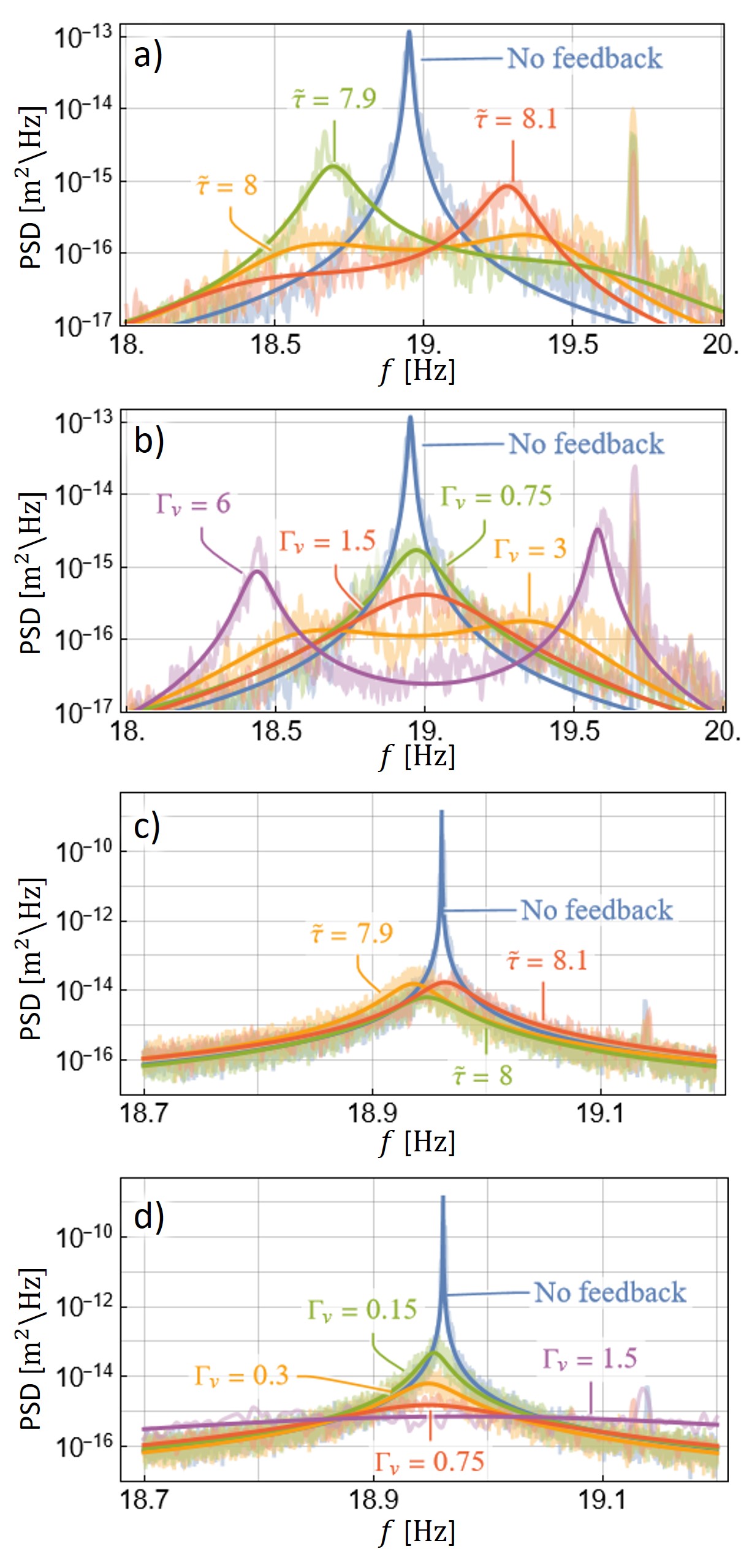
To characterise the effectiveness of feedback in this system, we performed delayed velocity feedback cooling experiments at moderate () and low () pressures, with varying time delays and feedback strengths. The measured power spectral densities are shown in Fig. 4, which match closely with Eq. 3. We describe the feedback using feedback strength , and dimensionless time delay , where is the natural frequency in the magnetic trap. The value of for low pressure is closely restricted to the damping from the ringdown measurement, while the value at moderate pressure is freely fit to the PSD. The parameter is fit from the experimental data. For the time delay , we first find an approximate value using our measured delay and the manual delay added by the FPGA, and then fit within one period deviation of this. It is also necessary to fit the overall scale of the PSD. This scale fitting accounts for the fact that Eq. 2 models a point particle following ideal Brownian motion, whereas our system consists of a three-dimensional extended plate. Measurements at the moderate pressure took 20 minutes, while at low pressure we required 7 hours to resolve the peak. As we show in the supplementary material, at low pressure without feedback, the resonance frequency drifts slightly during this time which may be caused by the thermal expansion of the composite plate.
The temperature is defined as being proportional to the integrated area under the PSD. We suppose that the system without feedback is in thermal equilibrium with the environment at . We find that cooling is strongest when is an integer number of periods, which from Eq. 2 means that the feedback is directly opposing the velocity. When deviates from an integer value the PSD broadens, and the peak shifts. At higher pressures with strong feedback strength, the time delay leads to visible sidelobes. Increasing the strength of the feedback leads to stronger cooling, and larger sidelobes at higher pressure. At low pressure, with a time-delay of periods and a feedback strength of , we attain a minimum temperature of . See the supplementary material for further discussion of the experimental data and analysis.
In conclusion, we demonstrate a novel magnetically levitated centimeter-size composite resonator by mixing the silica-coated graphite particles with wax. The insulating coating on the graphite prevents eddy currents flowing between adjacent particles, significantly reducing eddy damping, and hence increasing the quality factor by an order of magnitude. We report the cooling of vertical motional mode at different delays and feedback strengths, with good agreement between experiment and theory. At suitable feedback conditions, we realize strong cooling of the cm-sized resonator to a centre-of-mass temperature of . This work is a step forward towards the preparation of a macroscopic quantum spatial superposition, and shows the potential of our novel resonator for fundamental quantum physics and ultrahigh precision sensing.
We are grateful for the help and support provided by the Scientific Computing and Data Analysis Section, the Scientific Imaging Section and the Engineering Section at OIST.
References
- Delić et al. [2020] U. Delić, M. Reisenbauer, K. Dare, D. Grass, V. Vuletić, N. Kiesel, and M. Aspelmeyer, “Cooling of a levitated nanoparticle to the motional quantum ground state,” Science 367, 892–895 (2020).
- Magrini et al. [2021] L. Magrini, P. Rosenzweig, C. Bach, A. Deutschmann-Olek, S. G. Hofer, S. Hong, N. Kiesel, A. Kugi, and M. Aspelmeyer, “Real-time optimal quantum control of mechanical motion at room temperature,” Nature 595, 373–377 (2021).
- Gonzalez-Ballestero et al. [2021] C. Gonzalez-Ballestero, M. Aspelmeyer, L. Novotny, R. Quidant, and O. Romero-Isart, “Levitodynamics: Levitation and control of microscopic objects in vacuum,” Science 374, eabg3027 (2021).
- Winstone et al. [2023] G. Winstone, M. Bhattacharya, A. A. Geraci, T. Li, P. J. Pauzauskie, and N. Vamivakas, “Levitated optomechanics: A tutorial and perspective,” arxiv: 2307.11858 (2023), 10.48550/arXiv.2307.11858.
- Moore and Geraci [2021] D. C. Moore and A. A. Geraci, “Searching for new physics using optically levitated sensors,” Quantum Science and Technology 6, 014008 (2021).
- Young et al. [2019] J. Young, H. Biggs, S. Yee, and H. ElBidweihy, “Optical control and manipulation of diamagnetically levitated pyrolytic graphite,” AIP Advances 9, 125038 (2019).
- Fujimoto and Koshino [2019] M. Fujimoto and M. Koshino, “Diamagnetic levitation and thermal gradient driven motion of graphite,” Physical Review B 100, 045405 (2019).
- Yee et al. [2021] S. Yee, L. Oney, T. Cosby, D. P. Durkin, and H. ElBidweihy, “Photothermal actuation of levitated pyrolytic graphite revised,” APL Materials 9, 101107 (2021).
- Ewall-Wice et al. [2019] M. Ewall-Wice, S. Yee, K. DeLawder, S. R. Montgomery, P. J. Joyce, C. Brownell, and H. ElBidweihy, “Optomechanical Actuation of Diamagnetically Levitated Pyrolytic Graphite,” IEEE Transactions on Magnetics 55, 1–6 (2019).
- Chen et al. [2020] X. Chen, A. Keşkekler, F. Alijani, and P. G. Steeneken, “Rigid body dynamics of diamagnetically levitating graphite resonators,” Applied Physics Letters 116, 243505 (2020).
- Simon and Geim [2000] M. D. Simon and A. K. Geim, “Diamagnetic levitation: Flying frogs and floating magnets (invited),” Journal of Applied Physics 87, 6200–6204 (2000).
- Timberlake et al. [2019] C. Timberlake, G. Gasbarri, A. Vinante, A. Setter, and H. Ulbricht, “Acceleration sensing with magnetically levitated oscillators above a superconductor,” Applied Physics Letters 115, 224101 (2019).
- Yin et al. [2022] P. Yin, R. Li, C. Yin, X. Xu, X. Bian, H. Xie, C.-K. Duan, P. Huang, J.-h. He, and J. Du, “Experiments with levitated force sensor challenge theories of dark energy,” Nature Physics 18, 1181–1185 (2022).
- Romagnoli et al. [2023] P. Romagnoli, R. Lecamwasam, S. Tian, J. E. Downes, and J. Twamley, “Controlling the motional quality factor of a diamagnetically levitated graphite plate,” Applied Physics Letters 122, 94102 (2023).
- Xie et al. [2023] H. Xie, Y. Li, R. Li, Y. Leng, Y. Chen, L. Wang, D. Long, X. Bian, C.-K. Duan, P. Yin, P. Huang, and J. Du, “Suppressing mechanical dissipation of diamagnetically levitated oscillator via engineering conductive geometry,” Physical Review Research 5, 013030 (2023).
- Chen et al. [2022] X. Chen, S. K. Ammu, K. Masania, P. G. Steeneken, and F. Alijani, “Diamagnetic Composites for High-Q Levitating Resonators,” Advanced Science 9, 2203619 (2022).
- Semenenko and Esquinazi [2018] B. Semenenko and P. Esquinazi, “Diamagnetism of Bulk Graphite Revised,” Magnetochemistry 4, 52 (2018).
- Kim et al. [2017] Y. Kim, Y. Qian, M. Kim, J. Ju, S.-H. Baeck, and S. E. Shim, “A one-step process employing various amphiphiles for an electrically insulating silica coating on graphite,” RSC Advances 7, 24242–24254 (2017).