Non-Markovian dynamics of a superconducting qubit in a phononic bandgap
Abstract
The overhead to construct a logical qubit from physical qubits rapidly increases with the decoherence rate. Current superconducting qubits reduce dissipation due to two-level systems (TLSs) by using large device footprints. However, this approach provides partial protection, and results in a trade-off between qubit footprint and dissipation. This work introduces a new platform using phononics to engineer superconducting qubit-TLS interactions. We realize a superconducting qubit on a phononic bandgap metamaterial that suppresses TLS-mediated phonon emission. We use the qubit to probe its thermalization dynamics with the phonon-engineered TLS bath. Inside the phononic bandgap, we observe the emergence of non-Markovian qubit dynamics due to the Purcell-engineered TLS lifetime of . We discuss the implications of these observations for extending qubit relaxation times through simultaneous phonon protection and miniaturization.
A superconducting quantum processor with practical utility requires a large number of highly coherent, error-corrected qubits [EC1, EC2, EC3] to achieve quantum advantage [PhysRevA.95.032338, Shore, Grover]. Scaling recent logical qubit demonstrations [EC5] will require further improvements in gate and readout errors, as well as qubit footprint miniaturization. Miniaturizing superconducting qubits while improving their coherence is a challenging task, as miniaturization often leads to increased dissipation due to stronger coupling to two-level systems (TLSs). TLSs are surface or bulk defects within disordered or amorphous solids. Their strong electric and elastic dipole moments make them the dominant dissipation channel of current superconducting qubits [TLSreview, TLS2, TLS3]. Large planar qubits can reduce TLS-induced dissipation by minimizing energy participation of lossy interfaces [PhysRevLett.107.240501, 10.1063/1.3637047]. While this approach enabled improvements in qubit coherence up to a few hundred microseconds, simultaneous improvements to lifetime and footprint remain as outstanding challenges for scaling [irfanReview, T1qubit1, T1qubit2, T1qubit3].
In this work, we demonstrate an alternative approach to address the qubit footprint-dissipation trade-off by using a phonon-engineered qubit with a modified TLS bath. The electric and elastic dipole moments of TLSs mediate coupling between the superconducting qubit and the phonon bath, resulting in a phononic Purcell decay channel for the qubit. We use a phononic bandgap metamaterial as a mechanical Purcell filter to suppress the spontaneous phonon emission of TLSs, which in turn, influences the qubit relaxation time. We use the qubit to populate the TLS bath and to characterize the modified dissipative dynamics of the qubit and the TLSs [TLSpulses1, TLSpulses2]. We observe a strong enhancement of TLS lifetime in the phononic bandgap, along with a signature of qubit lifetime improvement. The observations are well-modeled with Solomon equations for a qubit coupled to a TLS environment [Solomon, spiecker2023solomon], and show non-Markovian qubit dynamics inside the phononic bandgap [nonMarkov1, nonMarkov2]. We discuss prospects for combining phonon protection and miniaturization to enable next-generation quantum processors.
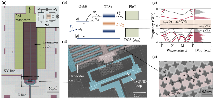
A superconducting qubit on a phononic bandgap metamaterial. According to the standard tunneling model, TLSs display strong electric (1 Debye) and elastic () dipole transition matrix elements that result in their strong interactions with superconducting circuits and phonons [TLSreview, ph1, ph2]. Their linear electromechanical response can be considered as atomic-scale piezoelectricity that converts the energy of superconducting qubits to phonons. As illustrated in Fig. 1(b), a TLS couples to the oscillating electric field of the qubit and dissipates it to the substrate via phonon emission at a rate . Consequently, the qubit experiences Purcell decay through each TLS with a rate . When higher order coherent effects can be ignored, the total qubit decay rate is then the sum of its intrinsic decay rate (from non-TLS sources) and the Purcell decay rates due to the TLS ensemble:
| (1) |
where is the detuning between the qubit and the th TLS, is their transverse coupling strength, and is the mutual decoherence rate in the absence of dephasing [Solomon].
The TLS lifetime is determined by the spontaneous phonon emission () rate and can be improved by suppressing the phonon density of states. If the spectral density of the phonon-protected TLS () is much smaller than mutual decoherence time (), the decay rates of the qubit () and TLSs () are closely linked [Rosen]. In this regime, the qubit decay is also expected to be suppressed, and the phononic crystal can be viewed as a mechanical Purcell filter that suppresses TLS-induced phonon emission from a superconducting qubit.
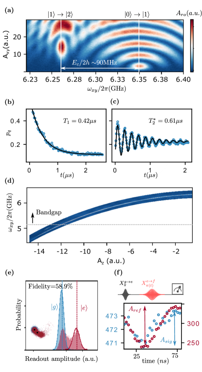
We study the modified qubit-TLS interactions on a phononic metamaterial with an engineered phonon density of states. Our device consists of an all-aluminum tunable transmon qubit on a suspended 2D phononic crystal membrane (Fig. 1(a)) [SOI]. The transmon consists of a compact interdigitated capacitor shunted to the ground through two symmetric Josephson junctions that form a superconducting quantum interference device (SQUID), as shown in Fig. 1(d). The SQUID loop is inductively coupled to a Z-control line for qubit frequency tuning. The transmon is capacitively coupled to an XY line for qubit control and to a coplanar waveguide resonator for fast dispersive readout. The device is mounted at the mixing chamber stage () of a dry dilution refrigerator and enclosed in multiple layers of radiation and magnetic shields. Details about the fabrication process, experimental setup, and measured qubit parameters are provided in the supplementary materials [SI].
The qubit capacitor is formed by interdigitating -wide fingers with gaps. The capacitor is fully engraved by the underlying phononic crystal structure as shown in Fig. 1(e). We design the capacitor using an effective medium description for the dielectric constant of the phononic crystal [SI]. The mass loading due to aluminum electrodes alters the phononic band structure and shifts the lower band edge from to (Fig. 1(c)), a signature that will be visible in subsequent qubit measurements. The common bandgap is centered at with a bandwidth. At , we measure a qubit lifetime of and Ramsey dephasing time of . We tune the qubit frequency from down to and do not observe any avoided level crossings with TLSs [SI]. The frequency response implies that the qubit incoherently interacts with a high-density bath of weakly coupled TLSs, consistent with the large mode volume and surface participation ratio of the design [XMON]. The designed and measured qubit properties can be found in the supplementary materials [SI].
Qubit-driven TLS hole-burning inside a phononic bandgap. Qubit-TLS interactions can result in coherent or incoherent dynamics depending on the ratio of interaction strength () to the mutual decoherence rate (). For , coherent qubit-TLS oscillations can be observed using swap spectroscopy with individual TLSs [coherentExchange]. For or in the case of dense TLS bath (approaching the continuum limit), the qubit and TLS population dynamics follow the Solomon rate equations [spiecker2023solomon]:
| (2) | ||||
| (3) |
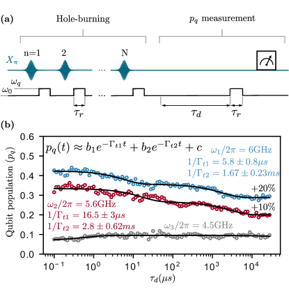
where refer to the qubit, TLS, and thermal excited state populations. In this regime, the average TLS lifetime can be measured by using a qubit-driven hole-burning sequence where we first excite the TLS bath using the qubit, and infer the bath properties from the qubit-bath thermalization dynamics. The hole-burning sequence in Fig. 2(a) consists of pulses that prepare the qubit in the state at a reference frequency . The excitation is subsequently exchanged with the TLS environment at by letting the qubit relax (). After hole-burning pulses, we use the qubit to probe the qubit-bath thermalization dynamics as they resonantly interact at frequency for duration .
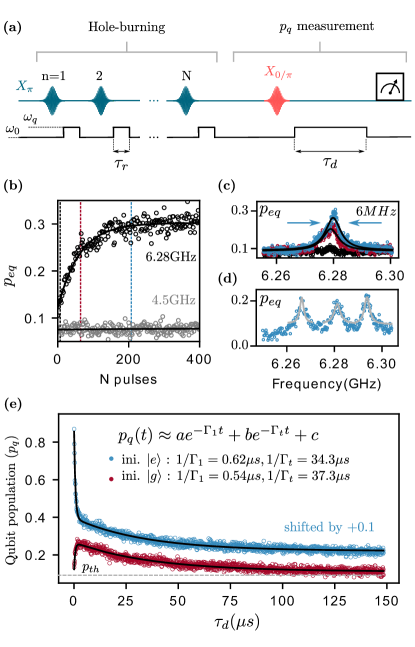
For , the qubit-TLS bath thermalization rate is faster than that of the TLSs to the phonon bath. In this regime, the qubit population approximates the equilibrium TLS population for . Fig. 2(b) shows the TLS population as a function of the number of hole-burning pulses . Around , the TLS bath can be populated from its thermal state to around near the center of the phononic bandgap (, black). This response shows the presence of long-lived TLSs and the emergence of a non-Markovian bath inside the phononic bandgap. This is in stark contrast to measurements performed at frequencies outside the phononic bandgap (, gray data), where the TLSs cannot be populated and measured using the pulse sequence due to their very short lifetime ( in Refs. [PhysRevLett.105.177001, PhysRevLett.111.080502]).
These observations can be explained by considering the steady-state populations that are determined by the TLS excitation rate through the qubit () and the energy decay rate from N TLSs resonantly interacting with the qubit (). The competition between these rates results in a steady state population . We use this relation to infer the effective number of TLSs resonantly interacting with the qubit TLSs at . Outside the phononic bandgap, due to the fast, Markovian relaxation of the TLS bath.
We probe the spectral distribution of the populated TLS bath, and observe a peak around the hole-burning frequency with a linewidth of , which includes the dephasing of the probe qubit and the probed TLSs (Fig. 2(c)). This indicates that the populated TLSs are dense () and share similar Purcell decay rates. As shown in Fig. 2(d), we use interleaved polarization pulses at different frequencies to saturate the TLS bath at different spectral regions, confirming the uniform, high-density distribution of the TLS bath (Fig. 2(d)). Under the dense and uniform bath approximation (), the rate equations simplify to [spiecker2023solomon, SI]
| (4) |
where , and represents the initial TLS population. For long-lived TLSs (), the solution of the differential equation can be approximated by a biexponential form [SI]. In Fig. 2(e), we probe the qubit decay after polarization pulses with the qubit initialized in the and states. By fitting the data to a biexponential form, we observe that, on average, the qubit lifetime is , where ) is the upward (downward) transition rate and depends on the TLS population. However, the qubit lifetime () remains independent of the TLS population, and the TLS lifetime () is independent of the qubit initialization [SI].
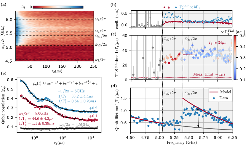
Non-Markovian dynamics of a phonon-protected superconducting qubit. To probe the effectiveness of the phononic bandgap, we performed the hole-burning pulse sequence used in Fig. 2(e) over the frequency range of , with a time delay of up to . This measurement captures both the slow and fast qubit dynamics from which the qubit () and TLS () lifetimes can be extracted. As shown in Fig. 3(a), the qubit population at long delays rapidly vanishes when we move the qubit outside the phononic bandgap (). The qubit decay due to TLSs can be estimated by noting that where (Eq.12, [SI]). We use the results presented in Fig. 3(b) to experimentally locate the band edges corresponding to the Si ( = ) and Si/Al ( = ) unit cells. For , a subset of the TLS bath leaves the bandgap and becomes short-lived, reducing both the qubit and average TLS lifetime (Fig. 3(c) and (d)). The phononic bandgap improves the TLS lifetime from values below the detection limit ( ) to an average of . The qubit lifetime (Fig. 3(d)) shows frequency dependence and experiences a smooth increase at the band edge due to the suppression of the TLS decay. An approximate model of the qubit-TLS interaction can be constructed from the TLS lifetimes and Eq. 1, from which we estimate a coupling strength , TLS density (in good agreement with the estimation from Fig. 2(c)), and the intrinsic qubit decay rate [SI].
We observe a small residual population inside the bandgap that decays far beyond suggesting the presence of a distribution of lifetimes for the TLS bath. To probe the long lifetime, we measured the relaxation dynamics of the qubit up to for three different frequencies as shown in Fig. 3(e). By fitting the data to a tri-exponential form , we extract two major time scales of the TLS bath. We measured ) of () for and of () for . Further investigation (detailed in [SI]) indicates that can increase further to () for if the qubit is detuned from the TLS population during the time delay , suggesting that the qubit Purcell limits the TLS lifetime at such long timescales.
Discussion and outlook. We showed that embedding a superconducting qubit inside a phononic bandgap enhances the TLS bath lifetime and results in non-Markovian qubit dynamics. The TLSs inside the phononic bandgap exhibited relaxation times ranging from to , extending up to when the qubit is detuned. Outside the bandgap, the relaxation time is less than (limit of detection), consistent with the measured values reported in [PhysRevLett.105.177001, PhysRevLett.111.080502]. While the precise mechanism limiting the TLS lifetime is currently unknown and subject to further study, we expect that lower disorder phononic metamaterials with larger bandgaps would result in further improvements to TLS lifetimes and suppress non-resonant relaxation mechanisms [moe, msphononRes].

An intriguing question is whether our phonon engineering approach, which leads to enhancements in TLS lifetimes, can also improve the lifetimes of future superconducting qubits. The qubit relaxation rate and its relation to TLS lifetimes are governed by Eq. 1, exhibiting two main limits that are illustrated in Fig. 4(a). The Fermi-limit is reached when the density of TLSs is large and approaches the continuum. In this regime, the TLS relaxation rate does not have a strong influence on the qubit lifetime, and the qubit decay rate follows that of Fermi’s golden rule, . The Purcell-limit is reached when the density of TLSs is small, and the relevant TLS distribution can be truncated to a few nearest neighbors. In this limit, the TLS relaxation rate has a direct influence on the qubit lifetime, and the qubit decay rate follows the Purcell formula, .
Our experiment is in the Fermi-limit where we observe only a modest improvement in the qubit lifetime inside the bandgap (Fig. 3(d)) due to the high TLSs density ( ). Commonly used qubits also operate in the Fermi-limit regime and mitigate TLS loss through optimized fabrication processes (reduce ) and large planar geometries that reduce TLS coupling strength (reduce ) and energy participation ratio [XMON, floating]. Therefore, phononic shielding is not expected to significantly improve their lifetime. However, phonon-shielding is expected to be more effective for miniaturized qubits operating in the Purcell-limit with low TLS density. We take the recently developed \chAl/AlO_x/Al merged element transmon (Mergemon) as an example [Mergmon], which has near unity energy participation ratio in the thin \chAlO_x dielectric layer, and a reported TLS density per unit volume of [XMON]. This allows us to establish a relation between the TLS density and coupling strength (), for varying Mergemon dimensions while keeping the qubit capacitance fixed. We also assume a uniform distribution of the TLSs, which allows for an analytical expression of the sum in Eq. 1 [SI]. In Fig. 4(b), the Mergemon relaxation time () is plotted as a function of the TLS relaxation time () and coupling strength (), assuming no intrinsic loss (). The color map clearly illustrates the Fermi-limited and Purcell-limited regimes, showing quantitatively the influence of the TLS lifetime on the qubit lifetime in each regime Our numerical calculations validate the limited improvement of the qubit lifetime in this work ( , ), and also affirm the reported Mergemon lifetime with ( , ) [Mergmon]. The Mergemon with area clearly operates in the Purcell limit, and phonon shielding is expected to improve its TLS-limited lifetime to the millisecond timescale. We note that the impact of the phononic crystal on the TLS and qubit Ramsey coherence time is currently unknown. We expect that the emergence of non-Markovian qubit-TLS dynamics and long relaxation times via phonon engineering will yield similar improvements in coherence via dynamical decoupling [DD1, DD2].
Acknowledgments. This work was primarily funded by the U.S. Department of Energy, Office of Science, Office of Basic Energy Sciences, Materials Sciences and Engineering Division under Contract No. DE-AC02-05-CH11231 in the Phonon Control for Next-Generation Superconducting Systems and Sensors FWP (KCAS23). Additional support was provided for device fabrication by the ONR and AFOSR Quantum Phononics MURI program. The devices used in this work were fabricated at UC Berkeley’s NanoLab. We thank Irfan Siddiqi and his group for assistance with Josephson junction and bandaid fabrication. The open-source Python package QICK [QICK] was used for measurements, QuTiP and SCQubit for device simulations [QuTiP, SCQubit], and Qiskit-Metal [qiskit-metal] for GDS generation.
References
- Shor [1995] P. W. Shor, Scheme for reducing decoherence in quantum computer memory, Phys. Rev. A 52, R2493 (1995).
- Fowler et al. [2012] A. G. Fowler, M. Mariantoni, J. M. Martinis, and A. N. Cleland, Surface codes: Towards practical large-scale quantum computation, Phys. Rev. A 86, 032324 (2012).
- Knill et al. [1998] E. Knill, R. Laflamme, and W. H. Zurek, Resilient quantum computation: error models and thresholds, Proceedings of the Royal Society of London. Series A: Mathematical, Physical and Engineering Sciences 454, 365 (1998).
- O’Gorman and Campbell [2017] J. O’Gorman and E. T. Campbell, Quantum computation with realistic magic-state factories, Phys. Rev. A 95, 032338 (2017).
- Shor [1997] P. W. Shor, Polynomial-time algorithms for prime factorization and discrete logarithms on a quantum computer, SIAM Journal on Computing 26, 1484 (1997).
- Grover [1996] L. K. Grover, A fast quantum mechanical algorithm for database search, in Proceedings of the Twenty-Eighth Annual ACM Symposium on Theory of Computing, STOC ’96 (Association for Computing Machinery, New York, NY, USA, 1996) pp. 212–219.
- Córcoles et al. [2015] A. D. Córcoles, E. Magesan, S. J. Srinivasan, A. W. Cross, M. Steffen, J. M. Gambetta, and J. M. Chow, Demonstration of a quantum error detection code using a square lattice of four superconducting qubits, Nature Communications 6, 6979 (2015).
- Müller et al. [2019] C. Müller, J. H. Cole, and J. Lisenfeld, Towards understanding two-level-systems in amorphous solids: insights from quantum circuits, Reports on Progress in Physics 82, 124501 (2019).
- Esquinazi [1998] P. Esquinazi, ed., Tunneling Systems in Amorphous and Crystalline Solids (Springer Berlin Heidelberg, 1998).
- Jäckle [1972] J. Jäckle, On the ultrasonic attenuation in glasses at low temperatures, Zeitschrift für Physik A Hadrons and nuclei 257, 212 (1972).
- Paik et al. [2011] H. Paik, D. I. Schuster, L. S. Bishop, G. Kirchmair, G. Catelani, A. P. Sears, B. R. Johnson, M. J. Reagor, L. Frunzio, L. I. Glazman, S. M. Girvin, M. H. Devoret, and R. J. Schoelkopf, Observation of high coherence in josephson junction qubits measured in a three-dimensional circuit qed architecture, Phys. Rev. Lett. 107, 240501 (2011).
- Wenner et al. [2011] J. Wenner, R. Barends, R. C. Bialczak, Y. Chen, J. Kelly, E. Lucero, M. Mariantoni, A. Megrant, P. J. J. O’Malley, D. Sank, A. Vainsencher, H. Wang, T. C. White, Y. Yin, J. Zhao, A. N. Cleland, and J. M. Martinis, Surface loss simulations of superconducting coplanar waveguide resonators, Applied Physics Letters 99, 113513 (2011).
- Siddiqi [2021] I. Siddiqi, Engineering high-coherence superconducting qubits, Nature Reviews Materials 6, 875 (2021).
- Kono et al. [2023a] S. Kono, J. Pan, M. Chegnizadeh, X. Wang, A. Youssefi, M. Scigliuzzo, and T. J. Kippenberg, Mechanically induced correlated errors on superconducting qubits with relaxation times exceeding 0.4 milliseconds (2023a), arXiv:2305.02591 [quant-ph] .
- Place et al. [2021] A. P. M. Place, L. V. H. Rodgers, P. Mundada, B. M. Smitham, M. Fitzpatrick, Z. Leng, A. Premkumar, J. Bryon, A. Vrajitoarea, S. Sussman, G. Cheng, T. Madhavan, H. K. Babla, X. H. Le, Y. Gang, B. Jäck, A. Gyenis, N. Yao, R. J. Cava, N. P. de Leon, and A. A. Houck, New material platform for superconducting transmon qubits with coherence times exceeding 0.3 milliseconds, Nature Communications 12, 1779 (2021).
- Wang et al. [2022] C. Wang, X. Li, H. Xu, Z. Li, J. Wang, Z. Yang, Z. Mi, X. Liang, T. Su, C. Yang, G. Wang, W. Wang, Y. Li, M. Chen, C. Li, K. Linghu, J. Han, Y. Zhang, Y. Feng, Y. Song, T. Ma, J. Zhang, R. Wang, P. Zhao, W. Liu, G. Xue, Y. Jin, and H. Yu, Towards practical quantum computers: transmon qubit with a lifetime approaching 0.5 milliseconds, npj Quantum Information 8, 3 (2022).
- Andersson et al. [2021] G. Andersson, A. L. O. Bilobran, M. Scigliuzzo, M. M. de Lima, J. H. Cole, and P. Delsing, Acoustic spectral hole-burning in a two-level system ensemble, npj Quantum Information 7, 15 (2021).
- Kirsh et al. [2017] N. Kirsh, E. Svetitsky, A. L. Burin, M. Schechter, and N. Katz, Revealing the nonlinear response of a tunneling two-level system ensemble using coupled modes, Phys. Rev. Mater. 1, 012601 (2017).
- Spiecker et al. [2023a] M. Spiecker, P. Paluch, N. Gosling, N. Drucker, S. Matityahu, D. Gusenkova, S. Günzler, D. Rieger, I. Takmakov, F. Valenti, P. Winkel, R. Gebauer, O. Sander, G. Catelani, A. Shnirman, A. V. Ustinov, W. Wernsdorfer, Y. Cohen, and I. M. Pop, Two-level system hyperpolarization using a quantum szilard engine, Nature Physics 19, 1320 (2023a).
- Spiecker et al. [2023b] M. Spiecker, A. I. Pavlov, A. Shnirman, and I. M. Pop, Solomon equations for qubit and two-level systems (2023b), arXiv:2307.06900 [quant-ph] .
- Xiang et al. [2021] L. Xiang, Z. Zong, Z. Zhan, Y. Fei, C. Run, Y. Wu, W. Jin, Z. Jia, P. Duan, J. Wu, Y. Yin, and G. Guo, Quantify the non-markovian process with intervening projections in a superconducting processor (2021), arXiv:2105.03333 [quant-ph] .
- Burkard [2009] G. Burkard, Non-markovian qubit dynamics in the presence of noise, Phys. Rev. B 79, 125317 (2009).
- Agarwal et al. [2013] K. Agarwal, I. Martin, M. D. Lukin, and E. Demler, Polaronic model of two-level systems in amorphous solids, Phys. Rev. B 87, 144201 (2013).
- Ioffe et al. [2004] L. B. Ioffe, V. B. Geshkenbein, C. Helm, and G. Blatter, Decoherence in superconducting quantum bits by phonon radiation, Phys. Rev. Lett. 93, 057001 (2004).
- Rosen et al. [2019] Y. J. Rosen, M. A. Horsley, S. E. Harrison, E. T. Holland, A. S. Chang, T. Bond, and J. L. DuBois, Protecting superconducting qubits from phonon mediated decay, Applied Physics Letters 114, 202601 (2019).
- Keller et al. [2017] A. J. Keller, P. B. Dieterle, M. Fang, B. Berger, J. M. Fink, and O. Painter, Al transmon qubits on silicon-on-insulator for quantum device integration, Applied Physics Letters 111, 042603 (2017).
- [27] Supplementary Information is available as Appendices.
- Barends et al. [2013a] R. Barends, J. Kelly, A. Megrant, D. Sank, E. Jeffrey, Y. Chen, Y. Yin, B. Chiaro, J. Mutus, C. Neill, P. O’Malley, P. Roushan, J. Wenner, T. C. White, A. N. Cleland, and J. M. Martinis, Coherent josephson qubit suitable for scalable quantum integrated circuits, Phys. Rev. Lett. 111, 080502 (2013a).
- Lisenfeld et al. [2019] J. Lisenfeld, A. Bilmes, A. Megrant, R. Barends, J. Kelly, P. Klimov, G. Weiss, J. M. Martinis, and A. V. Ustinov, Electric field spectroscopy of material defects in transmon qubits, npj Quantum Information 5, 105 (2019).
- Shalibo et al. [2010] Y. Shalibo, Y. Rofe, D. Shwa, F. Zeides, M. Neeley, J. M. Martinis, and N. Katz, Lifetime and coherence of two-level defects in a josephson junction, Phys. Rev. Lett. 105, 177001 (2010).
- Barends et al. [2013b] R. Barends, J. Kelly, A. Megrant, D. Sank, E. Jeffrey, Y. Chen, Y. Yin, B. Chiaro, J. Mutus, C. Neill, P. O’Malley, P. Roushan, J. Wenner, T. C. White, A. N. Cleland, and J. M. Martinis, Coherent josephson qubit suitable for scalable quantum integrated circuits, Phys. Rev. Lett. 111, 080502 (2013b).
- Chen et al. [2023] M. Chen, J. C. Owens, H. Putterman, M. Schäfer, and O. Painter, Phonon engineering of atomic-scale defects in superconducting quantum circuits (2023), arXiv:2310.03929 [quant-ph] .
- [33] G. S. MacCabe, H. Ren, J. Luo, J. D. Cohen, H. Zhou, A. Sipahigil, M. Mirhosseini, and O. Painter, Nano-acoustic resonator with ultralong phonon lifetime, Science , 840.
- Mamin et al. [2021] H. Mamin, E. Huang, S. Carnevale, C. Rettner, N. Arellano, M. Sherwood, C. Kurter, B. Trimm, M. Sandberg, R. Shelby, M. Mueed, B. Madon, A. Pushp, M. Steffen, and D. Rugar, Merged-element transmons: Design and qubit performance, Phys. Rev. Appl. 16, 024023 (2021).
- Kono et al. [2023b] S. Kono, J. Pan, M. Chegnizadeh, X. Wang, A. Youssefi, M. Scigliuzzo, and T. J. Kippenberg, Mechanically induced correlated errors on superconducting qubits with relaxation times exceeding 0.4 milliseconds (2023b), arXiv:2305.02591 [quant-ph] .
- Addis et al. [2015] C. Addis, F. Ciccarello, M. Cascio, G. M. Palma, and S. Maniscalco, Dynamical decoupling efficiency versus quantum non-markovianity, New Journal of Physics 17, 123004 (2015).
- Khodjasteh and Lidar [2005] K. Khodjasteh and D. A. Lidar, Fault-tolerant quantum dynamical decoupling, Phys. Rev. Lett. 95, 180501 (2005).
- Stefanazzi et al. [2022] L. Stefanazzi, K. Treptow, N. Wilcer, C. Stoughton, C. Bradford, S. Uemura, S. Zorzetti, S. Montella, G. Cancelo, S. Sussman, A. Houck, S. Saxena, H. Arnaldi, A. Agrawal, H. Zhang, C. Ding, and D. I. Schuster, The QICK (Quantum Instrumentation Control Kit): Readout and control for qubits and detectors, Review of Scientific Instruments 93, 044709 (2022).
- Johansson et al. [2012] J. Johansson, P. Nation, and F. Nori, Qutip: An open-source python framework for the dynamics of open quantum systems, Computer Physics Communications 183, 1760 (2012).
- Groszkowski and Koch [2021] P. Groszkowski and J. Koch, Scqubits: a Python package for superconducting qubits, Quantum 5, 583 (2021).
- Minev et al. [2021] Z. K. Minev, T. G. McConkey, J. Drysdale, P. Shah, D. Wang, M. Facchini, G. Harper, J. Blair, H. Zhang, N. Lanzillo, S. Mukesh, W. Shanks, C. Warren, and J. M. Gambetta, Qiskit Metal: An Open-Source Framework for Quantum Device Design & Analysis (2021).
- Jin et al. [2015] X. Y. Jin, A. Kamal, A. P. Sears, T. Gudmundsen, D. Hover, J. Miloshi, R. Slattery, F. Yan, J. Yoder, T. P. Orlando, S. Gustavsson, and W. D. Oliver, Thermal and residual excited-state population in a 3d transmon qubit, Phys. Rev. Lett. 114, 240501 (2015).
- Krinner et al. [2019] S. Krinner, S. Storz, P. Kurpiers, P. Magnard, J. Heinsoo, R. Keller, J. Lütolf, C. Eichler, and A. Wallraff, Engineering cryogenic setups for 100-qubit scale superconducting circuit systems, EPJ Quantum Technology 6, 2 (2019).
Appendix A Analytical modeling
In this section, we review the Solomon equations, which are rate equations that link the qubit population (central spin) to the population of a discrete ensemble of two-level systems (spin environment). Next, we review the limit of the Purcell decay rate under a uniform distribution of TLSs and constant coupling, illustrating the Purcell-limited and Fermi-limited regimes described in the text. We use the model to fit the qubit lifetime measurement presented in Fig. 3(d), as well as to compute Fig. 4 and identify the Fermi-limit and Purcell-limit regimes. The detailed analysis can be found in Refs. [Solomon, spiecker2023solomon].
A.1 The Solomon rate equations
The system is modeled assuming the qubit with population is coupled to a countable number of TLSs with populations . We denote and as the intrinsic relaxation rates of the qubit and the th TLS, respectively. The Purcell decay rate is given by
| (5) |
where is the detuning between the qubit and the th TLS, represents their transverse coupling strength, and the mutual decoherence is described by in the absence of dephasing. In the limit where the mutual decoherence of the qubit and TLS is sufficiently strong (), the interaction is incoherent, and the population dynamics are governed by the Solomon rate equations:
| (6) | ||||
| (7) |
From the initial conditions, one can determine the upward and downward transition rates of the qubit
| (8) |
from which, the qubit decay rate and its equilibrium population can be determined
| (9) | ||||
| (10) |
In the special case of identical Purcell decay rates () with a large number of TLSs, the qubit population exhibits biexponential decay behavior.
| (11) |
where is the sum of the Purcell decay rates, and represents the initial TLS population. It can be shown that in the case of long-lived TLSs (), an approximate solution to the above differential equation is a biexponential with fast and slow decay parts that encode the qubit and TLS relaxation rates, respectively. The slowly varying amplitude of population decay for the TLSs can be obtained by setting (adiabatic elimination), from which the approximate solution to Eq. 11 can be obtained:
| (12) |
A.2 Purcell decay rate of uniformly distributed TLSs
When the TLSs are spread in frequency and equally spaced by a period with a unified coupling strength and mutual decoherence rate , an analytical expression for the Purcell decay rate can be obtained as follows:
| (13) | ||||
| (14) | ||||
| (15) |
where , , with being the shift of the periodic TLS with respect to the qubit and can take any value between . In the limit of sparse TLSs (), the sum can be terminated to the few nearest interacting TLSs, and the decoherence follows the Purcell formula . In the limit of dense TLSs (), Eq. 15 is approximately equal to and which recovers the Fermi’s golden rule and is independent of the TLS relaxation time.
A.3 Qubit lifetime modeling
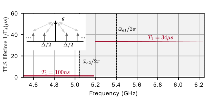
To gain more insight into the TLS bath properties, we fitted the measured qubit lifetime () of Fig. 3(d) to the qubit-decay formula (Eq. 1). We simplified the TLS lifetime () into a piecewise function of for and otherwise, as shown in Fig. S1. The model assumes that the TLSs are uniformly distributed at a constant density with uniform coupling strength (inset of Fig. S1). The sum of this distribution can be found analytically as in Eq. 15.
The intrinsic qubit decay due to Purcell decay via the readout resonator is set by , a decay rate of , and a qubit coupling strength of (Appendix B.1). For the model shown in Fig. 3(d), we find an average qubit-TLS coupling strength with and spans a range of . The values are in good agreement with the electrostatic simulation, where , and was assumed to be (Fig. S4(b)). However, the frequency dependence is quadratic instead of the frequency dependence expected from the single photon amplitude. One possible reason for the discrepancy is the oversimplification of the model, where, in practice, has a complicated spatial and frequency dependence. Finally, the density of TLS per unity frequency , and is constant as expected from the standard tunneling model and our estimate from hole-burning sequences [TLSreview]. The model fails to capture the region of the band edge, particularly between and (see Fig. 3(d)), where a large subset of TLSs are outside of the complete bandgap.
A.4 Case study: Merged-Element Transmon
Here we derive the scaling between TLS density and coupling strength used in Fig. 4(b) of \chAl/AlO_x/Al using Merged-Element Transmon (Mergemon) [Mergmon] as a reference. The Mergemon is modeled as a Josephson junction shunted with a parallel plate capacitor . The participation ratio is unity in the \chAlO_x dielectric with electric field , from which the coupling strength to defect TLSs with dipole moment is . The TLS density per unit frequency can be expressed as:
| (16) | ||||
where we assumed a qubit frequency and a capacitance , from which we obtain a zero-point voltage fluctuation of . The \chAlO_x permittivity has a TLS density per unit volume per unit frequency and a dipole moment of . For the Mergemon design reported in [Mergmon] with area and dielectric thickness , we have and .
Appendix B Measurements and simulations
In this section, we provide additional measurements of the transmon qubit coherence properties and calibration. Next, we repeat the measurement presented in Fig. 3(e) while detuning the qubit from the TLS bath. Lastly, we present the electrostatic simulation results from which we estimate the average qubit-TLS coupling strength ().
B.1 Qubit parameters and coherence properties
We report the measured parameters as follows: , , , , and . Here, represents the anharmonicity which is inferred from the two-photon excitation (Fig. S2 (a)), is the readout resonator frequency, denotes the dispersive shift, and represents the Lamb shift. These measured values imply a Josephson energy in the transmon limit (), where , and a charging energy . The readout-qubit coupling is , where , and the detuning is . The readout resonator has an extrinsic quality factor of and an intrinsic quality factor that ranges from the single photon limit to the power-saturated limit.
At , we measure a relaxation time and Ramsey dephasing time , as shown in Fig. S2(b) and (c), respectively. The qubit can be tuned continuously from with no signatures of swapping or splitting, suggesting incoherent interaction with the TLS environment (Fig. S2(d)). We note that the Purcell decay through the readout resonator is below and does not limit our coherence measurements.
Finally, the qubit population measurements presented in the manuscript are normalized to the fitted readout amplitude distribution when the qubit is prepared in the ground and excited states, respectively, as shown in Fig. S2(e). To identify read-out induced errors and obtain an accurate estimate of the thermal excited-state population of the qubit (), we record the amplitudes and of the Rabi-oscillations with and without a reference pulse respectively, as described in [ptherm]. The Rabi-oscillations are plotted in Fig. S2 (f), from which , which is approximately in our device.
B.2 Qubit-detuned TLS decay
The relaxation time of the TLS ensemble can be limited by Purcell decay through the qubit. This effect becomes pronounced when measuring a small number of long-lived TLSs (). To study this effect, we used a modified TLS hole-burning sequence where the qubit is detuned from the TLS frequency throughout the duration , allowing the TLS bath to decay independently, as shown in Fig. S3 (a). At the end of the sequence, the qubit is allowed to thermalize with the TLS population for , followed by a qubit readout measurement. The sequence was performed at the same frequency points of Fig. 3(e), and the results were fitted to the biexponential form . Detuning the qubit increased the long-TLS lifetime from to at , and from to at . This suggests that the TLS and the qubit can Purcell-limit each other’s lifetime.
B.3 Electrostatic simulation
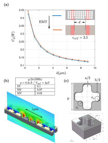
The vast scale difference between the features of the phononic crystal () and the qubit size ( capacitor) posed a problem in the electrostatic simulation of the qubit capacitance and its coupling to the readout resonator. This issue was addressed by resorting to the effective medium description of the phononic crystal. We find that an effective permittivity of a homogeneous slab between two metal electrodes separated by spacing , yields the same capacitance as that of the original phononic crystal substrate, as illustrated in Fig. S4(a). The results are in good agreement with the experimental data as well as the interdigitated capacitor simulation under periodic boundary conditions.
To estimate the average Qubit-TLS coupling strength , we performed a 3D electrostatic simulation for one period of the interdigitated capacitor, as shown in Fig. S4(b). We set the voltage between the two electrodes to =, which was estimated from the measured qubit parameters at using , and the transmon impedance . The average electric field in a thick layer on the substrate-vacuum (SV), substrate-metal (SM), and metal-vacuum (MV) interfaces are computed. From this data, the coupling strength to a TLS with a dipole moment of can be obtained via , and the results are summarized in the table of Fig. S4(b). The simulated phononic crystal unit cell parameters are provided in Fig. S4(c).
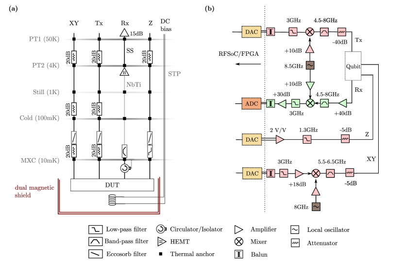
Appendix C Experimental setup and methods
This section provides the experimental details and methods for device fabrication, cryogenic setup, and the microwave electronics used in this work.
C.1 Device fabrication
In this section, we provide the detailed fabrication process flow for the phonon-protected transmon qubit (Fig. S5), which is a variation of the process presented in [SOI]. The SOI wafer used (supplied by Shin-Etsu) features a float zone silicon device layer with a thickness of and a crystal orientation of 100 ( ). The BOX is a -thick layer of \chSiO2 on top of a Czochralski-grown silicon handle layer with a thickness of ( ). The wafer, protected with a resist coating, is downsized from to (by MicroPE). Before deposition, the wafer is cleansed with \chH2SO4 and \chH2O2 (piranha solution) to remove organic residues, dipped in \chHCl to remove metallic contamination, and then in \chHF to remove the native oxide. Next, of aluminum is sputtered at a rate of . Since the contrast between materials with similar atomic numbers is poor under electron microscopy, and considering that the atomic masses of Si and Al are and , respectively, Nb metal () is used for subsequent electron-beam lithography (EBL) alignments. To define the markers, a -thick AZ-MIR 701 resist is exposed (Heidelberg MLA150), developed in MF-26A, and then descummed in \chO2 plasma. Next, a -thick \chNb layer is sputtered at a rate of , followed by an 1165 liftoff process. The wafer is then protected with resist and diced into dies for device processing.
The phononic crystal and release holes are then defined. Given the significant membrane size, proximity effect correction (PEC) was set up through BEAMER to address dose distortion. The pattern is subsequently exposed onto CSAR resist in an EBL step. The resist is cold-developed in AR600-546, and the pattern is transferred through two consecutive dry etching steps: a aluminum etch using a \chCl2/BCl3 chemistry, followed by a silicon etch using \chCl2/HBr/O2 chemistry. The addition of \chO2 helps preserve the aluminum thin bridges and corners from being thinned and rounded during the silicon etch. The sample is immediately immersed in water to passivate the chlorinated aluminum, followed by resist stripping in 1165 remover for .
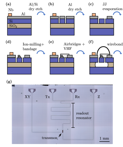
Next, the microwave circuit is defined by patterning PMMA A6 resist in an EBL step. To mitigate stitching errors, a field overlap is employed, along with a 2-multipass exposure configured using BEAMER. The resist is developed in MBIK/IPA at a 1:3 ratio, and the pattern is transferred by dry etching of Al and of Si. The silicon over-etching improves the surface for the Josephson junction evaporation. The sample is once again treated with water to passivate the chlorinated aluminum, and the resist is stripped by a soak in 1165 remover.
The Josephson junctions are defined through EBL exposure of a / EL9/CSAR bilayer resist. The exposed resist is then sequentially cold-developed (MBIK-IPA 1:3/AR600-546) and gently descummed in \chO2 plasma. The sample is loaded into a double-angle evaporator (Plassys MEB550) and pumped down to a base pressure of with the assistance of \chTi guttering. The subsequent steps are carried out in the following order: a Al evaporation at coordinates (, ); dynamic oxidation at for ; another Al evaporation at (, ); and a Al evaporation at (, ). The evaporation during all these steps is conducted at a rate of