Feasibility Analysis of In-Band Coexistence in Dense LEO Satellite Communication Systems
Abstract
This work provides a rigorous methodology for assessing the feasibility of spectrum sharing between large low-earth orbit (LEO) satellite constellations. For concreteness, we focus on the existing Starlink system and the soon-to-be-launched Kuiper system, which is prohibited from inflicting excessive interference onto the incumbent Starlink ground users. We carefully model and study the potential downlink interference between the two systems at 20 GHz and investigate how strategic satellite selection may be used by Kuiper to serve its own ground users while also protecting Starlink ground users. We then extend this notion of satellite selection to the case where Kuiper has limited knowledge of Starlink’s serving satellite. Throughout our analysis, we examine the distribution of interference and SINR as each constellation orbits the globe. Our findings reveal that there is nearly always the potential for very high and extremely low interference, depending on which Starlink and Kuiper satellites are being used to serve their ground users. Consequently, we show that Kuiper can protect Starlink ground users with high probability, by strategically selecting which of its satellites are used to serve its ground users. Simultaneously, Kuiper is capable of delivering near-maximal downlink SINR to its own ground users. This highlights a feasible route to the coexistence of two dense LEO satellite systems, even in scenarios where one system has limited knowledge of the other’s serving satellites.
I Introduction
A new paradigm of global broadband connectivity is unfolding as mega-constellations comprised of thousands of low-earth orbit (LEO) satellites are deployed to deliver wireless coverage across the globe. These LEO satellite communication systems circumvent the time-consuming challenges associated with deploying terrestrial infrastructure, which has left many regions and communities severely under-served—or even completely unserved—by terrestrial-based modes of connectivity [1]. Two of the most notable large-scale efforts in this pursuit are SpaceX’s Starlink [2, 3], with over 5,000 satellites currently in orbit, and Amazon’s Project Kuiper [4], which recently launched test satellites in October 2023 [5] and intends to launch 3,236 satellites throughout the decade.
These mega-constellations have already transformed the connectivity landscape and will be a key new source of broadband access in the 6G era [6, 7, 8]. However, among other concerns, there are important open questions regarding the coexistence of multiple mega-constellations [9, 10, 11, 12]. Unlike in traditional terrestrial cellular networks, frequency spectrum has been allocated to these satellite systems in a non-exclusive manner by the Federal Communications Commission (FCC) in the United States and other global spectrum regulators [13, 14]. To facilitate fair spectrum sharing, the FCC gives precedence (or incumbency) to systems which applied for launch rights in earlier so-called processing rounds than others. Consequently, it is the expectation of the FCC that each system either coordinate with or protect systems which acquired launch rights in earlier processing rounds.
Given the sheer number of satellites slated to launch and the growing number requesting launch rights [15], spectrum sharing across these satellite systems is far from trivial, especially when one considers the dynamics over time as satellites orbit. The feasibility of this coexistence is currently unclear and mechanisms to facilitate coexistence are even less established. In this work, we take a necessary first step by carefully investigating the severity of in-band interference over time between coexisting LEO satellite systems as their constellations orbit the globe, which ultimately sheds light on the efficacy of potential mechanisms to protect incumbent systems—and how imposing this protection may impact system performance.
I-A Related Work and Regulations
For decades, spectrum sharing has been investigated from both academic and regulatory perspectives with various applications in mind [16, 17]. The principle of spectrum sharing is concerned with so-called secondary systems not inflicting significant interference onto primary (or incumbent) systems when attempting to access some portion of frequency spectrum. Cognitive radio in the context of satellite systems has been proposed to manage and mitigate this interference via mechanisms including spectrum sensing, underlay, overlay, and database methods [18, 19, 9, 20]. The basic idea of underlay methods is that, when primary systems are deemed idle, a secondary system can use the free spectrum opportunistically [21, 22, 23]. On the other hand, overlay techniques allow a secondary system to use the spectrum concurrently with primary systems, assuming the secondary system does not substantially impact normal operation of the primary systems—which naturally leads to discussions and debate on what defines an acceptable level of interference. Various mechanisms along multiple dimensions have been studied to enable such overlay coexistence, with power allocation [21, 24, 25] and spatial domain beamforming [26, 27] being two prominent proposed routes to protect primary systems.
Regulatory bodies play a key role in establishing clear and comprehensive rules for spectrum sharing to realize coexistence between LEO satellite systems. The FCC, for instance, has employed an overlay coexistence paradigm, allowing secondary systems to inflict marginal interference onto primary systems, since this can facilitate more efficient and more widespread use of spectral resources [21, 28]. Defining the level at which interference becomes prohibitive to a primary system has proven to be a complicated task involving a variety of priorities from multiple perspectives, and as a result, it has been difficult to formulate and regulate a so-called protection constraint which the secondary system must oblige [29].
This protection constraint in satellite systems has been often formulated as a threshold on the interference power relative to the noise floor of the primary system, i.e., the interference-to-noise ratio (INR). For instance, it has been proposed that the resulting INR not be more than a threshold ranging from dB to an even stricter dB, perhaps for some specified fraction of time [29, 30, 31, 14]. Beyond looking purely at interference, a constraint on throughput degradation has also been considered to more meaningfully quantify the impact of interference on the primary system [32]. This is naturally more difficult to quantify from the perspective of the secondary system, since it depends on the signal quality of the primary system, and thus introduces open questions on how to satisfy and evaluate such a protection constraint. In this work, we will consider a pure INR constraint for concreteness. Also, it should be noted that a throughput degradation constraint can be suitably mapped to an interference power constraint for a given primary system signal quality.
I-B Contributions
In this paper, we analyze the coexistence paradigm laid forth thus far: the operation of a primary (or incumbent) LEO satellite system in the presence of a secondary LEO satellite system attempting to coexist in-band under the expectation that it protects the primary system. In light of active discussions in the regulatory domain and the impending launch of thousands of additional LEO satellites, this paper aims to characterize downlink interference and investigate the feasibility of the secondary system to reliably protect the primary system. We accomplish this by creating a high-fidelity simulation of the two LEO satellite systems using actual orbital parameters, transmit powers, antenna gains, and other system parameters reported in public FCC filings [33, 34]. Our aim is to shed light on the feasibility of coexistence in LEO satellite communication systems and to motivate future work proposing mechanisms to enable such coexistence. To accomplish this, we broadly investigate three important questions surrounding this coexistence between satellite systems.
Section IV: How much interference will be inflicted by the secondary system onto the primary? Perhaps the most fundamental concern we explore in this work is quantifying how much interference a secondary satellite may inflict onto a primary ground user. To do this, we evaluate the absolute bounds on this interference, as well as the bounds when conditioning on a particular primary satellite serving the ground user. We examine the distributions of both of these bounds over time as the satellites orbit around the globe and conclude that interference can be very high or extremely low at virtually any given time, depending heavily on the pair of primary and secondary satellites being used to serve downlink.
Section V: Can the secondary system protect the primary and what does it sacrifice in doing so? We then investigate how feasible it is for the secondary system to reliably protect a primary user under various interference constraints. In addition to mere feasibility, we also examine the number of secondary satellites capable of meeting this constraint. We then illustrate that strategic satellite selection may be used by the secondary system to serve its own ground user while also protecting a primary ground user. In doing so, we dissect the sacrifices in secondary system performance under such a technique, in terms of received signal-to-interference-plus-noise ratio (SINR). Again, we show all of this in distribution across the constellations’ orbits and remarkably discover that the secondary system often must only sacrifice a fraction of a decibel in SINR when protecting primary ground users.
Section VI: How much knowledge does the secondary system need about the primary? Finally, we conclude by reexamining the viability of protection when the secondary system has limited knowledge about which primary serving satellite is serving a given ground user. We observe that, on average, there are 10 secondary satellites capable of guaranteeing that primary ground users are protected, even when the secondary system has only modest knowledge about the vicinity of the primary serving satellite. While more uncertainty and a more stringent protection constraint certainly makes it more difficult to guarantee protection, we impressively find that the secondary system only sacrifices at most around 2 dB of SINR on average and around 4 dB in the worst case.
II System Model
This work considers two downlink LEO satellite communication systems, each operating independently to serve ground users on the surface of the Earth. Each of the two systems is comprised of a unique constellation of satellites orbiting at altitudes on the order of 500 km. We term one of the systems the primary system and the other the secondary system. The work herein is interested in assessing the in-band interference inflicted onto a given ground user of one system by a single satellite of the other system. As such, we consider the case where the two systems are transmitting downlink to nearby ground users at the same time and at the same carrier frequency of 20 GHz. In both systems, we assume each satellite employs a high-gain antenna (e.g., phased array or dish) to form a highly directional beam in the general direction of a ground user it aims to serve.
Let us define the transmit antenna gain of the primary satellite in the direction of a ground user as . Similarly, let be the receive antenna gain of user in the direction of primary satellite . The path loss between the two we denote as . With this, we can define the received signal-to-noise ratio (SNR) at a primary ground user served by its serving satellite as
| (1) |
where is the transmit power of and is the noise power at . Generalizing this notation to the secondary system, the received SNR at a secondary system ground user from its satellite is
| (2) |
As mentioned, we are particularly interested in the interference inflicted onto each system by the other. In this work, our focus is exclusively on the interference inflicted by individual satellites from each system, in order to draw concrete conclusions on the interplay between two satellites. Other sources of interference, such as from other beams [36] or other satellites across the constellations, is certainly a worthwhile direction for future work.111Multi-beam satellites serving multiple ground users at once are not considered explicitly in this work to focus on the impact of interference from a single pair of beams from a single pair of satellites. Suppose a secondary satellite inflicts interference onto a primary ground user being served by a primary satellite . Then, the resulting INR at the primary ground user is
| (3) |
Here, we have slightly extended the notation of and to make it clear that represents the transmit gain of the secondary satellite in the direction of the primary user when serves its secondary ground user . Similarly, represents the receive gain in the direction of the secondary satellite when the ground user steers its antenna toward its serving satellite . By virtue of this, the primary ground user’s INR depends on its primary serving satellite and on the secondary satellite . A primary satellite likewise will inflict interference onto a secondary ground user being served by satellite , leading to an INR at of
| (4) |
Together, the received SNR and INR at the primary ground user and at the secondary ground user dictate their SINRs, which take the familiar forms
| (5) | |||
| (6) |
A prohibitively high INR (e.g., dB) would lead to significant degradation in link quality where . As such, we are motivated to investigate the severity of interference in the sequel, but first we lay the groundwork on the methodology by which we accomplish such an investigation.
III Methodology of Our Feasibility Analysis
To conduct a thorough analysis on the feasibility of two dense LEO satellite communication systems coexisting in-band at 20 GHz, we consider the two preeminent commercial systems mentioned in the introduction: Starlink by SpaceX and Project Kuiper by Amazon. We consider Starlink as the primary system and Kuiper as the secondary system; this is motivated by the fact that Starlink has priority rights to the – GHz band for downlink transmission [3]. Indeed, based on current regulations, Kuiper is permitted to operate within that band along with Starlink, with an understanding that it not cause prohibitive interference to Starlink [4]—coinciding with the analyses herein.
III-A LEO Satellite Constellations
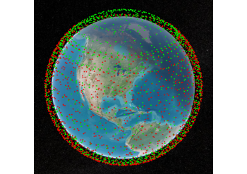
We simulate the constellation of satellites in Starlink and Kuiper in a Walker-Delta fashion [37] based on the orbital parameters detailed in Table I and Table II, which are extracted from public filings [4, 3, 35].222This work considers the first-generation Starlink constellation. The two constellations can be seen overlayed one another in Figure 1. Let be the set of all satellites in Starlink’s constellation. Similarly, let be the set of all satellites in Kuiper’s constellation. At a given instant in time, the systems aim to serve some primary ground user and secondary ground user .
| Altitude | Inclination | Planes | Satellites/Plane | Total No. Satellites |
|---|---|---|---|---|
| km | ||||
| km | ||||
| km | ||||
| km | ||||
| km |
| Altitude | Inclination | Planes | Satellites/Plane | Total No. Satellites |
|---|---|---|---|---|
| km | ||||
| km | ||||
| km |
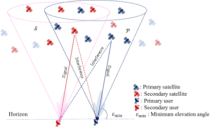
When aiming to serve these users in practice, each of these systems will select one satellite within its set of overhead satellites. More specifically, each system will select a satellite that is within some cone centered on the vector normal to the surface of the Earth at the ground user’s location, as shown in Figure 2. In practice, this set of overhead satellites is typically defined by a minimum elevation angle relative to the user’s horizon, at or above which a satellite must lie to be considered for selection. It is reasonable to assume both systems employ the same minimum elevation angle, which we assume herein to form the sets of overhead satellites as
| (7) | ||||
| (8) |
where denotes the elevation of a satellite relative to the horizon at a user ; we take [4] in the results that follow. Both and are functions of time, since the satellites overhead a particular user will vary as the constellations progress in their orbit; in LEO systems, satellites are overhead a typical user for about two minutes at most. We capture this time dimension by simulating the system over 24 hours with a resolution of 30 seconds.
III-B Satellites, Ground Users, and Path Loss
Having considered the – GHz band, we simulate the system at a carrier frequency of GHz with MHz of bandwidth. We assume all satellites and ground users in both the primary and secondary systems are equipped with standard uniform planar antenna arrays with half-wavelength spacing. We assume satellites are equipped with 6464 antenna arrays containing 4096 elements and perform canonical matched filter beamforming toward the user they are serving333For per-cell beamforming, users can be assumed located at the cell centers.; this delivers a maximum gain that is on par with the – dBi reported in filings [34]. The transmit power of each primary satellite is set to a maximum effective isotropic radiated power (EIRP) of dBW/Hz and that of each secondary satellite is set to dBW/Hz, according to FCC filings of Starlink [33] and Kuiper [34] when operating in the GHz band. We employ minor power control (factors on the order of dB) across each constellation to ensure the received signal strength from each satellite is approximately equal; this accounts for minor differences in path loss at slightly different altitudes.
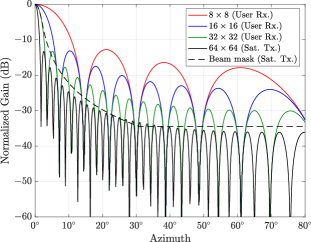
We consider ground users equipped with various numbers of antennas, ranging between 88, 1616, and 3232 antenna arrays. In Figure 3, we show the normalized azimuth cut of the gain delivered by the antenna array at each satellite and each of the ground user’s receive antenna arrays under consideration. Included in Figure 3 is the transmit beam mask, which is the maximum envelope of the antenna gain that satellites should abide by when transmitting, according to the International Telecommunication Union (ITU) [38]; our choice of antenna array at the satellite aligns quite well with this beam mask. All ground users are assumed to have a noise power spectral density of dBm/Hz plus a dB noise figure, based on recommendations published by 3rd Generation Partnership Project (3GPP) for rooftop-mounted users [39].
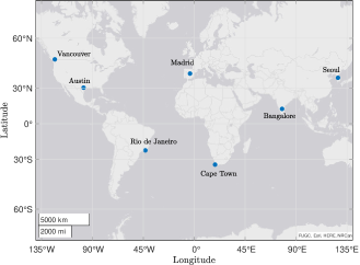
In order to assess worst-case interference, we assume the ground users are located at the same point, but empirically we found that even separations of up to 5 km result in the same conclusions drawn, due to the large footprint of a satellite’s beam on the surface of the Earth. In our simulation, we will examine the interference in multiple cities across the globe, namely Vancouver, Madrid, Seoul, Cape Town, Austin, Rio de Janeiro, and Bangalore, as shown in Figure 4. These cities vary widely in latitude, which impacts the number of satellites overhead the users. The path loss from a satellite to a ground user is modeled based on free-space path loss, as atmospheric and scintillation loss in the mid-latitude regions at elevation angles above are often observed to be marginal [40, 41, 42] and outdoor user terminals are assumed.
III-C Interference Protection Constraint
The interference inflicted by secondary satellites onto primary ground users is of particular importance from a regulatory perspective. The precise definition of prohibitive interference is an open question with ongoing discussions and efforts to define such [32]. In this paper, we investigate one common approach based purely on the strength of interference [29, 30, 31]. As one motivating example, the ITU defines prohibitive interference as when the effective temperature of the receiver increases by more than % [29, 14] when treating interference as noise. In other words, the interference power at a primary user must not be greater than % of its noise power . Denoting as the interference power inflicted by a secondary satellite onto a primary user being served by , we can directly write this constraint as
| (9) |
where we use to denote the interference threshold, in this case . We refer to (9) as the interference protection constraint, which assume the secondary system is obligated to satisfy. Because there are active discussions as to what an acceptable level of interference is, this work will examine a few different values for , namely dB, dB, dB, and dB.
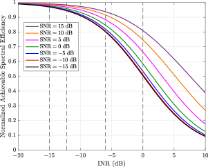
Consider Figure 5 illustrating the impact of on an arbitrary communication link. Shown is the degradation in achievable spectral efficiency , normalized to the link’s capacity , as a function of for various . When dB, the link’s achievable rate remains within 5% of the capacity for SNRs as low as dB—arguably a justified tax for coexistence. When interference is as strong as noise at dB, however, the loss varies greatly with SNR and approaches a 50% reduction at low SNR.
IV Bounds on the Interference Inflicted
onto a Primary Ground User
A natural starting point to begin analyzing the feasibility of coexistence is to examine the upper and lower bounds on the amount of interference that secondary satellites may possibly inflict on a primary ground user.
Definition 1: Absolute Bounds on INR.
At a given instant, the maximum and minimum interference that can be inflicted onto a ground user by the secondary system are respectively
| (10) | ||||
| (11) |
These metrics shed light on the severity of interference when coexisting, and looking at their distributions over time will indicate how this severity varies as satellites in both systems progress along their orbits. The distribution of , in particular, will dictate the need for an explicit interference protection constraint. For instance, if it is usually the case that dB, it may be argued that there is no need to consciously protect primary ground users; we will see shortly that this is not the case.
Definition 2: Primary Satellite Selection.
While the aforementioned absolute bounds are insightful, perhaps more useful are the maximum and minimum interference after the primary system has selected a satellite to serve its user . Considering it is the burden of the secondary system to protect the primary system, we assume that the primary system performs satellite selection based purely on maximizing its own SNR. Put simply, is defined henceforth as
| (12) |
In a real system, satellite selection would certainly involve a multitude of factors beyond maximizing SNR, but the exact algorithms employed by commercial systems remain proprietary and undisclosed to the public. Furthermore, our analysis has little dependence on the particular algorithm used in selecting the primary serving satellite.
Definition 3: Conditional Bounds on INR.
Now, with the assumption that a primary satellite selection has been made to serve , the bounds on interference conditioned on this selection are
| (13) | ||||
| (14) |
From the perspectives of both systems, these are presumably more practical bounds since they take into account the important fact, as highlighted in (3), that interference at the primary user depends on both the secondary satellite and its primary serving satellite . It naturally follows that and .
| City | Latitude | No. Primary Sat. | No. Secondary Sat. |
|---|---|---|---|
| Vancouver | 28.29 | 10.35 | |
| Madrid | 15.37 | 16.55 | |
| Seoul | 13.95 | 18.76 | |
| Cape Town | 12.66 | 17.72 | |
| Austin | 11.72 | 17.39 | |
| Rio de Janeiro | 10.45 | 12.98 | |
| Bangalore | 9.52 | 10.81 |
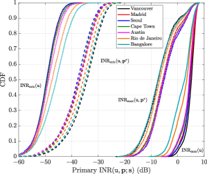
In Figure 6, we plot the empirical cumulative distribution functions (CDFs) of the absolute bounds and and the conditional bounds and across the globe for primary ground users equipped with 3232 antenna arrays. Each CDF is taken over time, and the color of each denotes the users’ location. Let us first examine the absolute bounds. The maximum interference is either just below or above the noise floor the vast majority of the time, and we observe that cities at higher latitudes (further from the equator) tend to see higher upper bounds . This is perhaps best explained by the fact that there simply tend to be more primary-secondary satellite pairs at higher latitudes, illustrated in Table III and attributed to Starlink’s higher concentration of satellites at latitudes around [2]. The steep distributions of suggest that—at virtually any given time and any location—there is a primary satellite and a secondary satellite in roughly the same direction as one another from the perspective of the primary ground user . The minimum interference possible is extremely low across all cities, reliably at least dB below the noise floor. In other words, there is virtually always some pair that can guarantee low interference at a primary user by virtue of low receive gain . Like with , the minimum interference levels are also more extreme for higher-latitude users since there are more possible primary-secondary satellite pairs.
Takeaway 1: There is the potential for extremely high or low interference, depending on the serving satellites.
These results on the absolute bounds on interference in Figure 6 suggest that there always exists the potential for extremely high interference if certain primary and secondary satellites are serving ground users in the same vicinity. On the flip side, however, there also always exists the potential for extremely low interference if a certain different pair of satellites is used to serve those same users.
Continuing an examination of Figure 6, we now look at the bounds on interference after the primary serving satellite has been selected. The conditional minimum interference is very low, more than dB below the noise floor across cities at all times; this suggests that there is always a secondary satellite that can offer low interference, even after the primary serving satellite has been chosen. Likewise, however, based on the conditional maximum , there is always the potential for a secondary satellite to inflict substantial interference that exceeds a threshold of dB, for example, laid forth before based on ITU recommendations [14].
Having conditioned on the primary serving satellite, the variability across cities is largely dictated by the number of secondary satellites overhead, whose average is listed in Table III. Cities with more secondary satellites overhead tend to see higher and lower . In this particular case, Kuiper’s constellation has fewer satellites at higher absolute latitudes and near the equator, so these satellites see less extreme and . In general, the distributions for both and across cities are fairly similar in shape and both differ in median by a few decibels. For the sake of concreteness, our results henceforth will be based on users located in Austin, Texas, with a latitude-longitude of (, ), which is where we see worst-case , along with Seoul.
Takeaway 2: Strategically selecting a secondary satellite can reliably protect primary ground users.
Even if the primary system performs satellite selection completely independently of the secondary system, the distribution of suggests that it is still viable for the secondary to strategically select its serving satellite such that low interference is inflicted on the primary ground user. Its ability to do so in a manner that delivers sufficiently high downlink to its own ground user is an open question we examine further in the sections that follow.
V System Performance under a Strict Interference Protection Constraint
Beyond solely examining interference, this section also aims to gauge both primary and secondary system performance in terms of SINR. To accomplish this, we will consider various methodologies by which the secondary system selects its serving satellite to serve a ground user . As with this entire paper, our goal here is not to propose a technique which maximizes system performance but rather to analyze performance under various techniques, with the goal of deriving insights that may drive more sophisticated techniques in future work.
Definition 4: Interference Protection Constraint.
When the secondary system selects its serving satellite in the presence of a primary user served by a primary satellite , imposing an interference protection constraint amounts to this selection satisfying
| (15) |
This is a strict instantaneous constraint in our formulation herein but could take other forms, potentially involving how frequently the threshold is violated, for instance. This could make for very interesting future work.
Definition 5: Number of Feasible Secondary Satellites.
A natural first question we investigate is the following: How many secondary satellites overhead are capable of satisfying the protection constraint? This can be formally expressed as the number of feasible secondary satellites defined as
| (16) |
where denotes the cardinality of a set .
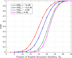
Recording throughout the duration of our simulation as both the primary and secondary satellites orbit allows us to populate its empirical CDF in Figure 7 for various thresholds . It can be seen that over half the time there are at least 15 secondary satellites capable of inflicting interference less than dB when serving their ground user . In other words, about 55% of the time, the secondary system has its choice between 15 or more satellites when forced to meet a strict interference constraint of dB. This number of feasible satellites reduces with a stricter threshold, whereas relaxing the threshold to dB, for instance, adds roughly two satellites to the pool in median. In all cases, there are rare but potentially concerning instances where only 6–12 satellites can meet the threshold, imposing limited flexibility in the secondary system’s ability to serve its ground user.
Definition 6: Greedy Max-SNR and Max-SINR Selection.
Let us begin by considering two greedy secondary satellite selection approaches that ignore the interference protection constraint. We first consider the case where the secondary system purely maximizes its own SNR by making its satellite selection as
| (17) |
Here, the use of can be thought of as representing an infinite interference threshold . Similarly, we also consider the case where the secondary system maximizes its own SINR as
| (18) |
It is valuable to consider both of these selections because, given the number of feasible secondary satellites , it may be the case that the secondary system inherently satisfies the interference protection constraint when purely maximizing its own SNR or SINR. We will see this is not the case, however.
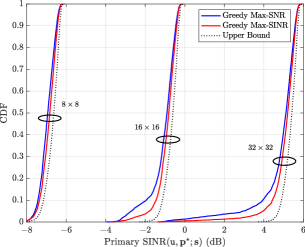
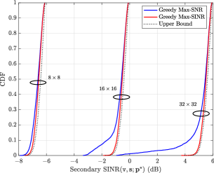
In Figure 8, we evaluate the performance of both the primary and secondary systems under the greedy max-SNR and greedy max-SINR secondary satellite selection schemes. First, let us consider Figure 8a, showing the empirical CDFs of primary SINR over time under each secondary selection scheme for various receive antenna arrays. The upper bounds on SINR (i.e., the interference-free SNR) for each array size is shown as the dotted line. For all three array sizes, purely maximizing SINR at the secondary system tends to yield primary system performance superior than purely maximizing SNR. Somewhat intuitively, it can thus be concluded that improving the secondary system’s SINR results in the primary system also enjoying higher SINR; in other words, by choosing a secondary satellite that reduces the interference inflicted onto its own ground user by the selected primary satellite , the interference inflicted onto the primary user is also inherently reduced. The superiority of max-SINR over max-SNR is most clearly seen in lower tail improvement, which has historically been a point of concern for network service providers.
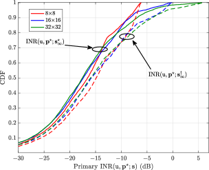
Now, we consider Figure 8b, depicting secondary system SINR analogous to Figure 8a. Many of the same trends can be observed but are more extreme. The improvement offered by maximizing SINR is more obvious as it drastically reduces the density of the lower tail and pulls the distribution quite close to its upper bound. Clearly, maximizing its own SINR would yield the preferred outcome from the perspective of the secondary system but this does not guarantee sufficiently low interference at the primary user at all times. This can be seen in Figure 9, which compares the primary INR under both secondary selection schemes. While maximizing the secondary SINR results in lower primary interference than maximizing SNR, a signification portion of the time, interference is well above the thresholds under consideration (e.g., dB). In Figure 9, we also observe a general increase in the upper tail of interference as the array size increases, since more antennas leads to a higher receive gain in instances when the primary and secondary serving satellites are in the same vicinity.
Takeaway 3: Max-SINR is preferable for both primary and secondary systems, but does not guarantee protection.
The secondary system selecting the satellite which maximizes its SINR is preferred over maximizing its SNR from the perspective of both the secondary system and the primary system, since it will inherently reduce interference at both systems’ ground users. Doing so, however, does not guarantee that the interference inflicted onto the primary system will be below a plausible protection threshold. This motivates the need to explicitly protect the primary ground user when selecting the secondary serving satellite.
Definition 7: Protective Max-SNR and Max-SINR Selection.
We now augment the previous selection methodologies by enforcing the interference protection constraint (15) to form protective max-SNR selection
| (19a) | ||||
| (19b) | ||||
and protective max-SINR selection
| (20a) | ||||
| (20b) | ||||
Outright maximizing SINR via (20) would presumably yield superior secondary system performance over (19), but it very well may be the case that meeting the interference protection constraint and maximizing its own SNR would inherently improve its own SINR. This makes it interesting to compare these selections and their resulting performance.
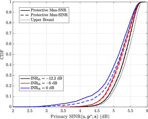
In Figure 10, we compare the performance of both of these protective secondary satellite selection schemes for various interference thresholds with 3232 antenna arrays at the ground users. First and foremost, comparing Figure 10a to Figure 8a illustrates that incorporating the protective constraint improves primary SINR, greatly reducing the lower tail and highlighting the importance of explicitly incorporating the protection constraint into secondary satellite selection. Aside from this, protective max-SINR selection clearly improves primary SINR over protective max-SNR, magnifying when is relaxed. This is again due to the inherent reductions in interference at the primary user when maximizing the secondary SINR; in this case, sometimes those reductions push interference further below , but this is typically only observed when is less strict.
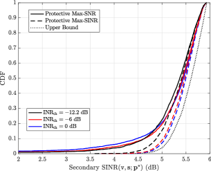
Now, in Figure 10b, we derive important conclusions on secondary system performance when abiding by the protection constraint. The shown upper bound is the interference-free SNR. The first key observation is that both protective max-SNR and protective max-SINR are capable of delivering appreciable SINRs the overwhelming majority of the time. Protective max-SNR exhibits a heavier tail, since the only interference reduction it enjoys is the inherent reduction when satisfying the protection constraint. Protective max-SINR, however, impressively sees minor degradation even for the most stringent constraint. As the constraint is relaxed, protective max-SINR approaches the upper bound but ultimately falls short due to interference it incurs from the primary system.
Takeaway 4: Protective Max-SINR is preferable for both systems and guarantees primary users are protected.
Protecting a primary ground user does not necessarily impede the secondary system from attaining appreciable SINR, falling short of its upper bound by fractions of a decibel. The gains in secondary system performance by maximizing its SINR while meeting the protection constraint are non-negligible compared to maximizing its SNR. As an added benefit, when the secondary system maximizes its SINR, the primary system also enjoys an increase in SINR.
It is certainly a welcome sight that impressive performance can be achieved while meeting very stringent protection constraints, but it is perhaps more useful to understand how many secondary satellites are capable of such, since systems will naturally be tasked with serving multiple users with multiple satellites. We investigate this further in the following.
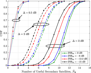
Definition 8: Number of Useful Secondary Satellites.
Definition 5 introduced , the number of secondary satellites capable of satisfying the protection constraint. We extend this notion to define the number of useful secondary satellites , capable of satisfying the protection constraint while also offering a secondary SINR within a factor of from the maximum possible SNR (i.e., ).
| (21) |
Figure 11 exhibits the empirical CDF of the number of useful secondary satellites for various and various thresholds . Earlier in Figure 7, we saw that there were typically 12–18 feasible secondary satellites, depending on the protection constraint. Comparing this to Figure 11, we can see that this decreases to 8–12 satellites if we wish to lose at most dB in secondary SINR. This decreases further to 4–8 satellites with dB and to 1–2 satellites with dB.
Takeaway 5: Multiple satellites are useful for coexistence at any give time.
While there are often 12–18 secondary satellites which can satisfy even the most stringent protection constraint, there are typically only 1–2 of those satellites which can also deliver near-maximal SINR. This number grows to 4–12 satellites, however, if – dB in SINR loss can be tolerated.
Definition 9: Satellite Angular Separation.
In order to derive real-world meaning from these four different techniques for secondary satellite selection, we introduce the notion of angular separation between two satellites. Let us define as the absolute angular separation between two satellites and with respect to the primary ground user .
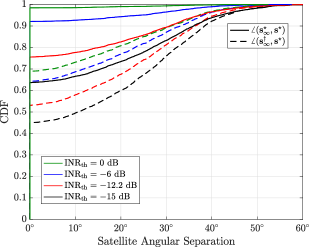
In Figure 12, the solid lines depict the distributions (over time) of the angular separation between the protective max-SINR selection and the greedy max-SINR selection for various . The dashed lines correspond to the angular separation between the protective max-SINR selection and the greedy max-SNR selection . From the solid green line, we can conclude that about 99% of the time ; in other words, the protection constraint of dB is met inherently by simply maximizing the secondary system SINR. As the protection constraint is tightened to dB (red solid line), only about 75% of time does . The remaining roughly % of the time, the two will typically be separated by to . Comparing the solid green line to the dashed green line, we can see that it is far less common yet still frequent that maximizing the secondary system SNR also inherently satisfies the protection constraint; as a result, there tends to be more angular separation.
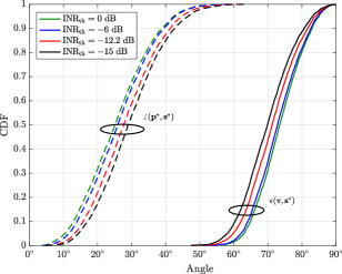
Now, in Figure 13, the dotted lines show the angular separation between the primary serving satellite and the protective max-SINR secondary satellite . In general, the two satellites are separated by to , with the separation tending to increase as the protection constraint is made more stringent. The solid lines depict the elevation angle of the secondary satellite . With a relaxed protection constraint, the secondary SINR is typically maximized by selecting a satellite at higher elevations, typically to . As the protection constraint is made more stringent, the SINR-maximizing satellite is typically at elevations about lower, closer to the horizon.
VI System Performance under Uncertainty
In the previous section, we characterized system performance under secondary satellite selection techniques which protect a primary user receiving downlink from its serving satellite . Among others, one noteworthy practical challenge in these secondary satellite selection problems is the assumption that the secondary system has knowledge of . This section explores when this is not the case and how such uncertainty may impact system performance.
Definition 10: Uncertainty in Primary Satellite Selection.
Suppose rather than knowing for certain that the primary ground user is being served by , the secondary system instead only knows that the true serving satellite is within some set of primary satellites . To model this uncertainty, suppose the secondary system knows (or is confident) that the angular separation of the true primary serving satellite and some direction is within . Then, the set of possible serving satellites can be expressed as follows.
| (22) |
As before, the absolute angular difference operation is from the perspective of the primary ground user .
It is worth emphasizing that, at any given time, it is reasonable to assume that the secondary system has near-real-time knowledge of all primary satellite locations since this is public information; this could perhaps be used by the secondary system to populate , assuming it can acquire some estimate on the vicinity of the true primary serving satellite. For the sake of simulation, we construct this set at a given instant by considering all satellites within some angular distance of the primary satellite which maximizes SNR, defined before as in (12); in other words, we take . Note that we have not assumed the true primary serving satellite to necessarily be in the direction of nor will it be relevant in the results that follow, since we will focus on worst-case secondary system performance under uncertainty.
Definition 11: Protection Constraint under Uncertainty.
When faced with complete uncertainty about which primary satellite within the set is serving user , ensuring a selected secondary satellite does not exceed a threshold amounts to the constraint
| (23) |
Naturally, this is a stricter protection constraint than (15), when the secondary system has knowledge of , since it must not inflict prohibitively high interference for several potential primary serving satellites.
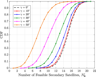
Definition 12: Number of Feasible Satellites under Uncertainty.
Under uncertainty, the number of secondary satellites satisfying this stricter protection constraint is
| (24) |
Naturally, we have as a consequence of uncertainty.
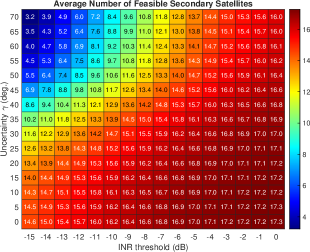
In Figure 14, we highlight how the level of uncertainty and the interference threshold impact the number of feasible secondary satellites . First, in Figure 14a, we depict the empirical CDF of over time for various when the threshold is dB. Notice that the shape of the distribution remains fairly unchanged but undergoes a shift leftward as uncertainty increases. In median, there are typically more than fewer feasible satellites when , compared to when is known exactly, and 8 fewer when . In Figure 14b, we depict a heatmap of the time-averaged for a wide range of and . Even with extreme uncertainty and a very strict threshold, on average there are satellites that can guarantee the protection constraint is met across the entire set of possible primary satellites . At dB, there are more than 10 feasible satellites on average when uncertainty is or less. With at most of uncertainty, the average number of feasible satellites decreases from 17 to 12, compared to a virtually unconstrained and perfectly known scenario (i.e., when dB and ).
Even though we only assume one secondary satellite is chosen to serve a ground user , it is useful to examine how many satellites are feasible, since it sheds light on the flexibility the secondary system has in meeting the constraint. For instance, considering a practical secondary system would be tasked with serving multiple users at once across its constellation of satellites, it may benefit greatly from having more satellites capable of meeting a strict protective constraint at any given time. If , for example, the secondary system would be forced to serve the user with the lone feasible satellite or not serve the user at all if the satellite is occupied serving another user. This also highlights how multi-beam satellites may relax the challenges associated with this process.
Takeaway 6: Multiple secondary satellites are feasible under a stringent protection constraint and uncertainty.
Even with a very stringent interference protection constraint such as dB, there are on average more than 10 secondary satellites capable of protecting a primary ground user under modest knowledge of its serving satellite. Likewise, with extreme uncertainty about the primary serving satellite, there are more than 10 secondary satellites capable of protecting a primary ground user under a modest interference constraint.
Definition 13: Protective Max-Guaranteed-SINR Selection.
We now investigate the effects of this uncertainty on secondary system performance. To do so, we introduce the notion of maximum guaranteed secondary system SINR under uncertainty, which can be accomplished by solving the following constrained satellite selection problem.
| (25a) | ||||
| (25b) | ||||
Notice that is the minimum SINR that the secondary system will see; we refer to this as the guaranteed SINR, since for any
| (26) |
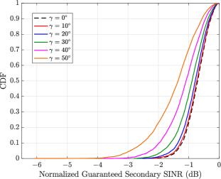
In Figure 15a, we show the distribution of guaranteed SINR achieved by the secondary system over time, normalized to its upper bound, the maximum SNR (i.e., from (17)), where dB. By normalizing the guaranteed SINR in this way, we can measure the degradation in secondary system signal quality due to the combined effects of (i) abiding by the protection constraint under uncertainty and (ii) interference from the primary system. Without any uncertainty , there is at worst about a dB gap in guaranteed SINR from its upper bound and less than a dB gap the majority of the time. When is not known precisely, this uncertainty leads to losses in guaranteed SINR, especially at the lower tails, but this is most apparent only under high uncertainty. For , the guaranteed secondary SINR falls short by only a fraction of a dB from that with perfect knowledge of . When uncertainty increases to , there is only about a dB sacrifice in median, but a much more substantial lower tail is present. Nonetheless, it is a welcome sight that, the overwhelming majority of the time, less than dB is sacrificed by the secondary system in protecting (and being interfered by) the primary system, even with very limited knowledge on the primary serving satellite.
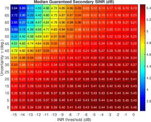
Figure 15b extends this analysis by depicting the median guaranteed secondary SINR (unnormalized) for various interference thresholds and levels of uncertainty. It can be observed in the most extreme case that the minimum guaranteed SINR is above dB in median, about dB short of the upper bound. In terms of median guaranteed SINR, the secondary system is not significantly impacted by making the protection threshold more strict under modest uncertainty. When uncertainty exceeds , however, we begin to see that more stringent leads to more dramatic losses in median guaranteed SINR.
Takeaway 7: With limited knowledge about the primary serving satellite, the secondary system can still protect primary ground users and deliver high SINR .
Even when the secondary system does not know precisely which primary satellite is serving a particular ground user, if it has limited knowledge on the general vicinity of the primary serving satellite, it can still select a satellite which guarantees the primary user is protected and delivers appreciable SINR. Although, uncertainty leads to wider variability in the SINR the secondary system is capable of guaranteeing, the severity of such is most apparent under fairly high uncertainty. With that being said, the number of feasible satellites does decrease, limiting the freedom a practical secondary system would have in scheduling its satellites when serving multiple ground users and protecting the primary system.
From Figure 15a, it is certainly remarkable at first glance that the secondary system sacrifices at most only dB in guaranteed SINR under an uncertainty of and a strict interference constraint of dB, compared to exact knowledge of . The SNR delivered by a secondary satellite is dictated mostly by its path loss to the ground user, which itself depends on the satellite altitude and elevation angle [39]. Across all overhead satellites, there is typically – dB of variability in SNR delivered to a given user [36]. Combining this with the fact that satisfying the interference protection constraint often inherently reduces interference onto the secondary ground user, a feasible secondary satellite typically only sacrifices at most roughly – dB in SINR when is strict. Selecting the feasible satellite which maximizes SINR therefore often results in less than – dB of loss.
VII Conclusion and Future Directions
This work has investigated the feasibility of in-band coexistence between two heterogeneous LEO satellite communication systems by analyzing two preeminent commercial entities: SpaceX’s Starlink as the primary system and Amazon’s Project Kuiper as the secondary. We saw that at virtually anytime, at least one secondary satellite has the potential to inflict prohibitively high interference onto a primary ground user, even with highly directional beams at both the user and satellite. However, it was also observed that there almost always exists one (or often more) secondary satellites which inflict acceptable interference onto the primary user while also delivering downlink SINR that approaches its upper bound. We showed that this is case even when the secondary system is not certain which primary satellite is serving that particular user. Based on these results, it can be concluded that in-band coexistence is indeed feasible through strategic satellite selection, but there remain open questions on practical mechanisms to execute such selection.
Interesting extensions of this evaluation on coexistence would be to cases where each satellite forms multiple beams, where the secondary system has uncertainty about the locations or receivers of primary ground users, and where the secondary system is tasked with scheduling satellites across its entire network. Creating novel techniques that leverage satellite selection or other means—potentially harnessing machine learning—to facilitate coexistence between LEO satellite communication systems on a network scale would be extremely valuable contributions. It would also be useful to formulate and extensively evaluate other interference protection constraints, considering, for example, a probabilistic constraint in time, constraints on handover frequency, and even user mobility. Investigating how coexistence may be facilitated by limited cooperation between the primary and secondary systems would make for interesting future work as well.
Acknowledgments
We thank Arun Ghosh, Michael Hicks, Anil Rao, and Vikram Chandrasekhar from Amazon’s Project Kuiper for their valuable discussions and feedback on our methodology and results.
References
- [1] Y. Xiaohu et al., “Towards 6G wireless communication networks: vision, enabling technologies, and new paradigm shifts,” Sci. China Inf. Sci., pp. 110 301–110 376, Nov. 2020.
- [2] J. C. McDowell, “The low earth orbit satellite population and impacts of the SpaceX Starlink constellation,” Astrophys. J. Lett., vol. 892, no. 2, p. L36, Apr. 2020.
- [3] Application for modification of authrization for the SpaceX NGSO satellite system. Space Exploration Holdings, LLC, Apr. 2020.
- [4] Technical Appendix, Application of Kuiper systems LLC for authority to launch and operate a non-geostationary satellite orbit system in Ka-band frequencies. Kuiper Systems LLC, Jul. 2019.
- [5] J. C. McDowell. Jonathan’s space report. Oct. 2023. [Online]. Available: https://planet4589.org/space/con/star/stats.html
- [6] S. Chen, S. Sun, and S. Kang, “System integration of terrestrial mobile communication and satellite communication —the trends, challenges and key technologies in B5G and 6G,” China Commun., vol. 17, no. 12, pp. 156–171, Dec. 2020.
- [7] M. Sheng et al., “6G service coverage with mega satellite constellations,” China Commun., vol. 19, no. 1, pp. 64–76, Jan. 2022.
- [8] X. Lin et al., “On the path to 6G: Embracing the next wave of low earth orbit satellite access,” IEEE Commun.Mag., vol. 59, no. 12, pp. 36–42, Dec. 2021.
- [9] M. Höyhtyä et al., “Application of cognitive radio techniques to satellite communication,” in IEEE Int. Symp. Dyn. Spectr. Acc. Netw., Oct. 2012, pp. 540–551.
- [10] H. Xie, Y. Zhan, G. Zeng, and X. Pan, “LEO mega-constellations for 6G global coverage: Challenges and opportunities,” IEEE Access, vol. 9, pp. 164 223–164 244, Dec. 2021.
- [11] S. Maleki et al., “Cognitive spectrum utilization in Ka band multibeam satellite communications,” IEEE Commun. Mag., vol. 53, no. 3, pp. 24–29, Mar. 2015.
- [12] C. Braun, A. M. Voicu, L. Simić, and P. Mähönen, “Should we worry about interference in emerging dense NGSO satellite constellations?” in IEEE Int. Symp. Dyn. Spectr. Acc. Netw., Dec. 2019, pp. 1–10.
- [13] Title 47 code of federal regulations (CFR) 26.261(c) sharing among NGSO FSS space stations. FCC. [Online]. Available: https://www.ecfr.gov/current/title-47/chapter-I/subchapter-B/part-25/subpart-C/section-25.261#p-25.261(e)
- [14] Maximum permissible levels of interference in a satellite network (GSO/FSS; non-GSO/FSS; non-GSO/MSS feeder links) in the fixed-satellite service caused by other codirectional networks below 30 GHz. ITU-R. S 1323, Feb. 2015.
- [15] A. A. Kriezis and W. Q. Lohmeyer, “U.S. market access authorization timeline analysis for megaconstellation networks.” [Online]. Available: https://www.osstp.org/fcc-analysis
- [16] Facilitating opportunities for flexible, efficient, and reliable spectrum use employing cognitive radio technologies, Notice of proposed rule making and order, document 03-322. FCC, Dec. 2003.
- [17] O. Kodheli et al., “Satellite communications in the new space era: A survey and future challenges,” IEEE Communs. Surv. Tut., vol. 23, no. 1, pp. 70–109, Oct. 2020.
- [18] L. B. Cardoso da Silva, T. Benaddi, and L. Franck, “Cognitive radio overlay paradigm towards satellite communications,” in IEEE Int. Black Sea Conf. Commun. Netw., June 2018, pp. 1–5.
- [19] E. Biglieri, “An overview of cognitive radio for satellite communications,” in IEEE AESS Eur. Conf. Satell. Telecommun., 2012, pp. 1–3.
- [20] M. Höyhtyä et al., “Database-assisted spectrum sharing in satellite communications: A survey,” IEEE Access, pp. 25 322–25 341, 2017.
- [21] S. K. Sharma, S. Chatzinotas, and B. Ottersten, “Satellite cognitive communications: Interference modeling and techniques selection,” in Adv. Sat. Multimedia Sys. Conf. and Signal Process. Space Commun. Workshop, Oct. 2012, pp. 111–118.
- [22] M. Jia et al., “Broadband satellite-terrestrial communication systems based on cognitive radio toward 5G,” IEEE Wireless Commun., vol. 23, no. 6, pp. 96–106, Dec. 2016.
- [23] J. Hu et al., “Energy-efficient cooperative spectrum sensing in cognitive satellite terrestrial networks,” IEEE Access, pp. 161 396–161 405, 2020.
- [24] D. Nguyen, M. T. Nguyen, and L. B. Le, “Cognitive radio based resource allocation for sum rate maximization in dual satellite systems,” in Proc. IEEE VTC, Sep. 2017, pp. 1–5.
- [25] Y. Ruan, L. Jiang, Y. Li, and R. Zhang, “Energy-efficient power control for cognitive satellite-terrestrial networks with outdated CSI,” IEEE Syst. J., vol. 15, no. 1, pp. 1329–1332, Mar. 2021.
- [26] S. K. Sharma, S. Chatzinotas, and B. Ottersten, “Transmit beamforming for spectral coexistence of satellite and terrestrial networks,” in Int. Conf. Cogn. Radio Oriented Wireless Netw., Jul. 2013, pp. 275–281.
- [27] C. Zhang et al., “Spatial spectrum sharing for satellite and terrestrial communication networks,” IEEE Trans. Aerosp. Electron. Syst., vol. 55, no. 3, pp. 1075–1089, Jun. 2019.
- [28] P. Gu, R. Li, C. Hua, and R. Tafazolli, “Dynamic cooperative spectrum sharing in a multi-beam LEO-GEO co-existing satellite system,” IEEE Trans. on Wireless Commun., vol. 21, no. 2, pp. 1170–1182, Feb. 2022.
- [29] C. M. Guiterrez and M. D. Gallagher, “Interference protection criteria phase 1-compilation from existing sources,” National Telecommunications and Information Administration, Oct. 2005.
- [30] Protection criteria related to the operation of data relay satellite systems. ITU-R. SA 1155-2, Jul. 2017.
- [31] Apportionment of the allowable error performance degradations to fixed-satellite service (FSS) hypothetical reference digital paths arising from time invariant interference for systems operating below 30 GHz. ITU-R. S 1432-1, Apr. 2006.
- [32] Report and order and further notice of proposed rulemaking. FCC, Mar. 2023. [Online]. Available: https://docs.fcc.gov/public/attachments/DOC-392201A1.pdf
- [33] Attachment sched S tech report for modification on satellite space stations filling. Space Exploration Technologies Corp., Apr. 2016.
- [34] Attachement sched S tech report, Application of Kuiper systems LLC for authority to launch and operate a non-geostationary satellite orbit system in Ka-band frequencies. Kuiper Systems LLC, Jul. 2019.
- [35] Order and authorization and order on reconsideration. FCC, Apr. 2021.
- [36] E. Kim, I. P. Roberts, and J. G. Andrews, “Downlink analysis and evaluation of multi-beam LEO satellite communication in shadowed rician channels,” IEEE Trans. Veh. Technol., Sep. 2023, (early access).
- [37] J. G. Walker, “Circular orbit patterns providing continuous whole earth coverage.” Royal Aircraft Establishment, Technical Report 702011, pp. 369–84, Nov. 1970.
- [38] Satellite antenna radiation patterns for non-geostationary orbit satellite antennas operating in the fixed-satellite service below 30 GHz. ITU-R. S 1528.
- [39] Solutions for New Radio (NR) to support non-terrestrial networks (NTN). Technical Report 38.821 v.16.0.0, 3GPP, Dec. 2019.
- [40] Recommendation ITU-R P 676-11. ITU-R. P 676-11, Sep. 2016.
- [41] Propagation data and prediction methods required for the design of Earth-space telecommunication systems. ITU-R P.618-13, Dec. 2017.
- [42] Study on New Radio (NR) to support non-terrestrial networks (NTN). Technical Report 38.811, v.15.3.0, 3GPP, Jul. 2020.