Evaluation of a Motion Measurement System for PET Imaging Studies
Abstract
Positron Emission Tomography (PET) enables functional imaging of deep brain structures, but the bulk and weight of current systems preclude their use during many natural human activities, such as locomotion. The proposed long-term solution is to construct a robotic system that can support an imaging system surrounding the subject’s head, and then move the system to accommodate natural motion. This requires a system to measure the motion of the head with respect to the imaging ring, for use by both the robotic system and the image reconstruction software. We report here the design and experimental evaluation of a parallel string encoder mechanism for sensing this motion. Our preliminary results indicate that the measurement system may achieve accuracy within 0.5 mm, especially for small motions, with improved accuracy possible through kinematic calibration.
I Introduction
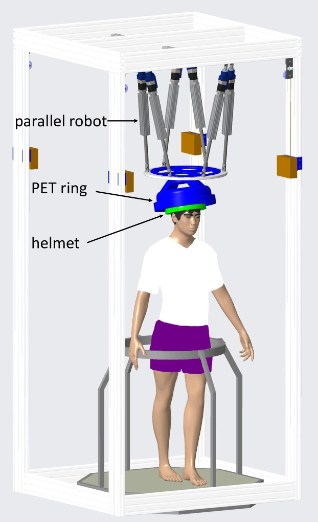
Positron Emission Tomography (PET) relies on the injection of a radioactive tracer, which is then preferentially absorbed by specific tissues (based on the choice of tracer). The absorbed tracer emits positrons that react with nearby electrons, creating a pair of annihilation (gamma) photons that travel in opposite directions and are detected by the PET imaging ring. Higher sensitivity can be achieved by placing the PET detectors as close as possible to the subject. For brain imaging during natural activities, such as locomotion, the ideal solution would be a wearable PET imaging ring, such as the Helmet PET [1], except that with current technology, a PET imaging ring with sufficient sensitivity for neuroscience research would weigh 10 kg or more [2] (other estimates are 15-20 kg). Thus, we are instead exploring the use of a robotic system to suspend the PET imaging ring over the subject’s head and to actively compensate for head motion while the subject performs activities such as walking on a treadmill, as illustrated in Fig. 1. The goal of the robotic system is to keep the imaging ring approximately centered around the subject’s head (coarse motion compensation), with residual motion corrected by the image reconstruction algorithm (fine motion compensation). This is an example of human-robot interaction, where the robot must safely move in proximity of the human.
Given the high safety requirement when robotically moving a 15-20 kg weight over a human head, we plan to have a redundant measurement system consisting of both optical and mechanical sensing of the subject’s head motion with respect to the PET imaging ring, possibly fused with inertial sensing. This paper focuses on the design and experimental evaluation of a mechanical sensing system, consisting of six string encoders connected between the PET imaging ring and a safety helmet attached to the subject’s head. Our current plan is to use this system as the primary measurement for control of the robotic system (coarse motion compensation) because it is robust and can provide high-frequency measurements (on the order of 1 kHz). In contrast, optical sensing can provide high accuracy, but provides lower-frequency feedback (on the order of 30-60 Hz) and can occasionally fail to provide a measurement. We have not yet determined which measurement system to use for the fine motion compensation performed by the image reconstruction software. According to the imaging scientists, motion measurements should be accurate to within about 0.5 mm for this task. Thus, one of our goals is to evaluate whether the mechanical sensing system can meet this accuracy requirement.
Motion correction is also relevant for conventional PET imaging, and several researchers have investigated different approaches for sensing this motion. Especially, different markerless approaches have been studied extensively in recent years. Olesen [3, 4] describes a system that incorporates a near infrared light emitting diode into a digital light processing projector to result in a surface scanner, tracking the head motion by creating a 3D point cloud on the head surface. This system is mounted directly on the PET imaging device, and while providing high accuracy of less than 0.3 mm, adds considerable weight to the imaging ring. This setup also requires clearance between the patient’s head and the imaging ring for the emission and processing of the near infrared light, which is in conflict with our desire for a compact, highly-sensitive imaging system. Other methods rely more on image processing, thus reducing the amount of computation required compared to such a 3D surface imaging system. Kyme [5] and Anishchenko [6] utilized four cameras to record the patient’s head, followed by detection of facial features from the video, and determine the 6 degree-of-freedom (DOF) movement of the head. However, this markerless approach could only achieve an accuracy of about 2 mm.
Chamberland [7] uses positron emission fiducial markers to detect tumor movement for more accurate targeting in radiotherapy. The advantage of this approach is that motion can be directly measured in the images, which is ideal for the fine motion correction, but is too slow to control the robot for the coarse motion correction. Also, the fidicual marker would be visible in the reconstructed image and could interfere with measurements of nearby brain structures.
We previously analyzed motion capture and accelerometer data from subjects during overground and treadmill walking, respectively, to determine the typical range of head motion, as well as head velocity and acceleration [8]. We assumed a helmet of dimension 263 mm x 215 mm and evaluated the ability of a simulated robot to compensate for the recorded head motion, without colliding with an imaging ring of 300 mm diameter. Our results indicated that this was feasible, given a robot that could compensate for typical head motions within about 100 ms. Our goal in this work is to develop a measurement system that will enable us to experimentally verify this assertion. Section II presents the measurement system design and implementation, including integration of a robot for providing ground-truth displacements. This is followed by accuracy results in Section III and conclusions in Section IV.
II Methods
This section describes the design of our mechanical measurement system, using parallel string encoders, followed by a kinematic analysis, details of the system construction, and homing procedure (to determine initial string lengths). We next discuss how the string lengths are adjusted to compensate for lateral motion within their guide channels. Finally, we describe the method for determining the transformation between the UR3 robot coordinate system and string coordinate system.
II-A Mechanical design
For our mechanical measurement system, we decided to use string encoders, attached between the imaging ring and the helmet. This creates a parallel structure (essentially a passive parallel robot), where we wish to compute the forward kinematics to convert the measured joint positions (string encoder lengths) to the Cartesian pose. Given that we need at least 6 string encoders to provide 6 DOF, there are many different ways that these can be configured. We selected a Stewart platform structure over other commonly used cable-driven parallel robots (CDPRs) [9] and parallel measuring structures [10], because it is a compact and widely used mechanical structure [11] and is less susceptible to string interference (i.e., the strings should not come into contact with each other, the imaging ring, or the helmet).
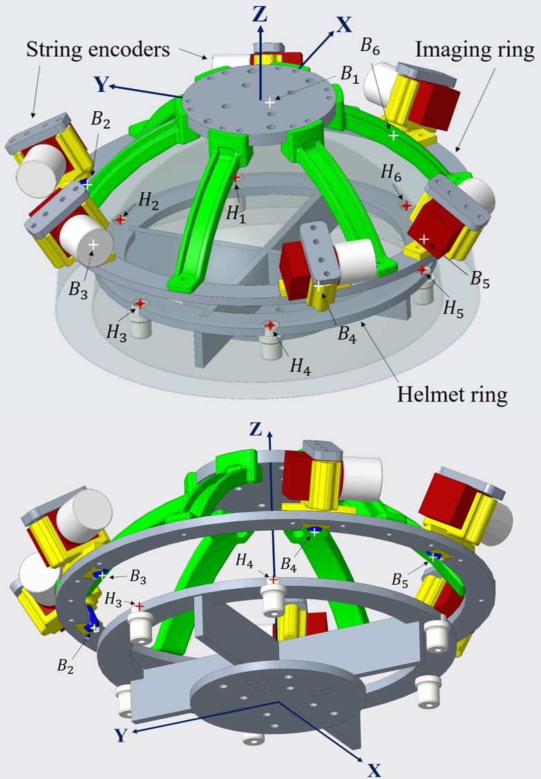
We explored several Stewart platform designs, considering motion sensitivity (resolution) and isotropic performance. Details of the design optimization will published separately. The final design is based on approximating the imaging ring as a sphere of 300 mm diameter and the helmet/head as a sphere of 250 mm diameter. We note that this is just an approximation for our initial evaluation, as the imaging ring is expected to be cylindrical, not spherical, and the helmet is expected to be elliptical with a major axis of about 263 mm in diameter. We created two attachment rings – one to represent the imaging ring and the other to represent the helmet. Due to the placement of the rings within the respective spheres, the imaging ring diameter is 261.32 mm and the helmet ring diameter is 235.42 mm. Figure 2 shows a CAD model of the string encoder system generated with Creo. where the top figure indicates the locations of the string attachment points, and the bottom figure provides a more direct view of the attachment points on the imaging ring. The orientation of the system is also shown in the figure, and in the nominal configuration, the helmet coordinate axes are aligned with the base (PET imaging ring) coordinate axes. The string attachment points are given in Table I, where and () are the base and helmet attachment points respectively, as seen in the nominal configuration.
| Point | X | Y | Z | Point | X | Y | Z |
|---|---|---|---|---|---|---|---|
| 121.39 | 48.35 | 73.67 | 96.99 | 66.70 | 42.06 | ||
| -18.82 | 129.30 | 73.67 | 9.27 | 117.35 | 42.06 | ||
| -102.56 | 80.95 | 73.67 | -106.26 | 50.64 | 42.06 | ||
| -102.56 | -80.95 | 73.67 | -106.26 | -50.64 | 42.06 | ||
| -18.82 | -129.30 | 73.67 | 9.27 | -117.35 | 42.06 | ||
| 121.39 | -48.35 | 73.67 | 96.99 | -66.70 | 42.06 |
II-B String encoder kinematics
The string encoder system is a Stewart platform and thus we use a standard kinematics formulation, where the inverse kinematics (from Cartesian pose to string lengths) is easily computed given the mounting points of the strings on the base (PET imaging ring) and moving platform (helmet). Specifically, if and () represent the coordinates of the base and helmet attachment points, respectively, and is the Cartesian pose (transform) of the helmet with respect to the base, the computed string lengths, , are given by the following inverse kinematics solution:
| (1) |
The forward kinematics is more complex and is computed numerically, as described in [12]. Given measured string lengths, , the estimated Cartesian pose of the helmet with respect to the base, , is computed iteratively by:
| (2) |
where is the iteration counter, is the Jacobian and is the inverse kinematic solution, eq. (1), corresponding to . In this equation, the Cartesian pose is represented by Euler angles, using the intrinsic ZYX convention, i.e., with respect to the helmet coordinate axes shown in Fig 2. We subsequently refer to the rotation angle about the z-axis as roll, the angle about the y-axis as pitch, and the angle about the x-axis as yaw. The iteration is terminated when the string length error, given by is less than a specified threshold (0.01 mm in our case) or if the iteration counter reaches a specified limit (50 in our implementation). We typically see convergence in 3-4 iterations. Note that for a parallel structure, it is more practical to compute the inverse Jacobian and then obtain the Jacobian by numerically computing the pseudo-inverse.
II-C System construction
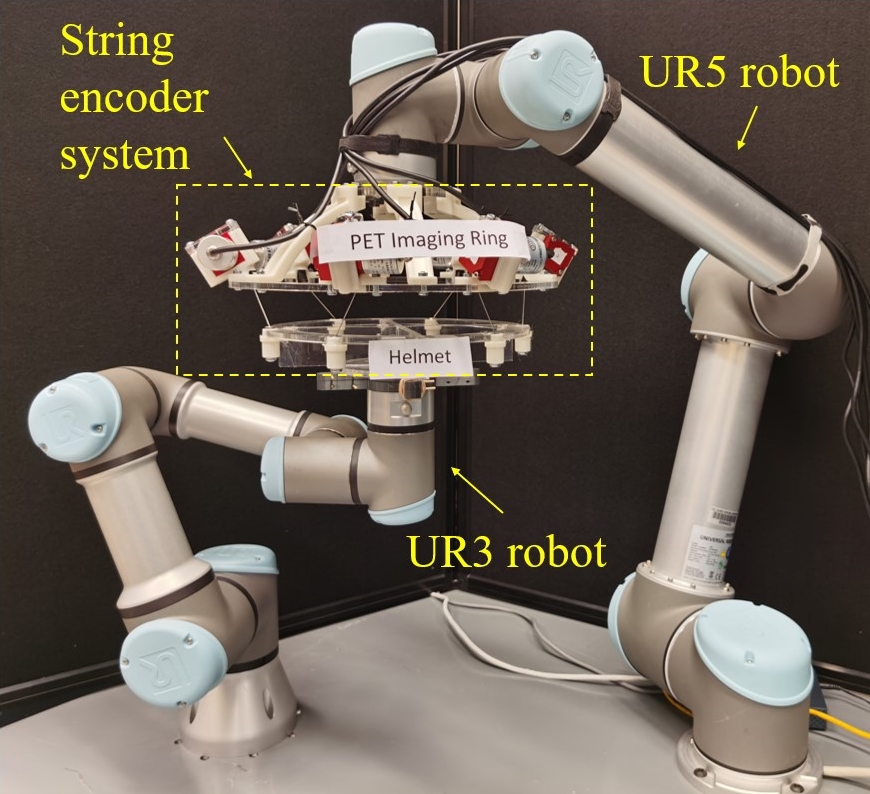
To study the motion of the helmet (head) relative to the PET imaging system, using the above presented kinematic model, we employed an experimental setup consisting of a string encoder measurement system, with a UR3 robot (Universal Robots, Odense, Denmark) to move the helmet ring and a UR5 robot to support the PET imaging ring, as shown in Fig. 3. In the experiments reported here, the UR5 robot is not moved. In future proof-of-concept work, it will move based on the measured head motion to attempt to keep the (mock) PET imaging ring centered over the helmet. In the longer term, the weight of an actual PET imaging ring exceeds the UR5 payload and therefore a custom robot, as shown in Fig. 1, will instead be used. We interfaced to the UR3 robot via TCP, using its real-time script interface.
The six string encoders (MPS-XXXS-200MM-P, Miran Industries, China) each have a measurement range of 200 mm at a resolution of 60 counts/mm. The string encoder bodies were attached on the PET imaging ring while the mobile ends were attached to the helmet. All custom-made parts of the string encoder measurement system were built with laser-cut acrylic plates combined with 3D printed (Stratasys F170) ABS components. The geometry of the imaging ring, helmet, and strings connection points were defined based on the Stewart platform kinematics presented above.
The string encoders are incremental encoders with quadrature outputs (A and B channels) and an index pulse (I). We created a custom board to interface these signals to an FPGA board developed for the da Vinci Research Kit (dVRK) [13]. The FPGA firmware already included a 4-channel encoder interface module, which was modified to handle up to 8 channels. We implemented our test software on a PC and connected to the FPGA board via a UDP socket.
II-D Homing procedure
Because the string encoders measure relative displacements, it is necessary to perform a homing procedure to set the initial absolute displacement. This homing procedure is performed by utilizing the index pulses provided by the string encoders, which are transmitted on a different channel than the regular quadrature pulses. Through its 200 mm range of travel, each string encoder produces three index pulses, equally spaced apart by 4000 counts, which is equivalent to one-third of the total measurement range. The location of the first index pulse differs for each string encoder, and the absolute displacement that corresponds to this first index pulse was recorded before installing each of the string encoders.
With this information, each time the string encoder system is powered on, the measuring ends can be brought as close to the encoder bodies as possible in order to trigger the first index pulse, which is captured by the FPGA firmware. By calculating the difference between these values and the known positions, we can set the offsets to obtain the correct absolute displacements.
II-E Calibration of string length adjustment
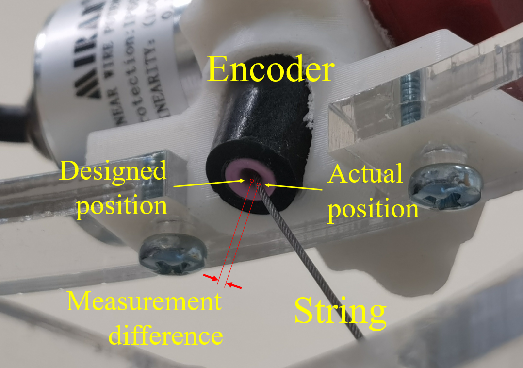
We observed that the attachment points for the string encoders are affected by a slight deviation from the ideal model presented earlier. As demonstrated in Fig. 4, the designed attachment point for the string is the center of its circular guide channel on the body of the encoder, but the string in fact makes contact with the edge of the channel instead of going through the center. A potential solution would be to adjust the attachment point coordinates to account for the shift. However, when the helmet platform moves, the string also frequently shifts its position within the channel, especially when the movement is around the center point. This would require the attachment point coordinates to be updated during operation, which would complicate the approach.
Instead, we recognized that due to the angled orientation of each string encoder, the string almost always lies against the edge of the channel—in fact, with our range of motion implemented below, the string never extends from the center along the direction of the guide channel. Therefore, the actual reading of each string encoder is less than the nominal situation where the string passes through the center of the attachment point, and this difference is always a fixed amount. We then attempted to identify an optimal value for this string length offset through empirical testing, experimenting with offset lengths ranging from -2 mm to 6 mm. For each setting, we put the robot through a set range of motion in all 6 degrees of freedom and collected a series of 66 data points. Evaluation of the results and determination of the optimal string length offset are presented in the following section.
II-F Transformation between robot and string encoder system
To compare the displacement measured by the string encoder system with the ground-truth displacement provided by the UR3 robot, a transformation between the two coordinate systems is required. We accomplished this by considering that the transformation between the PET imaging ring (base) and the robot, , is fixed for this experiment because the UR5 robot does not move. The string encoder system measures the transformation between the PET imaging ring and the helmet, , and after setting the robot tool center point (TCP) to be coincident with the center of the helmet, the robot interface can output the corresponding transformation between the robot and the helmet, . Consequently, , and for a constant position of the base, the string encoder system only needs to query the robot once to obtain and then compute . Afterwards, the measurements from the string encoder system can be converted to a 6 DOF position in the robot coordinate system by computing , and the full 6 DOF pose can be extracted from the resulting transformation.
III Results
III-A Experimental setup
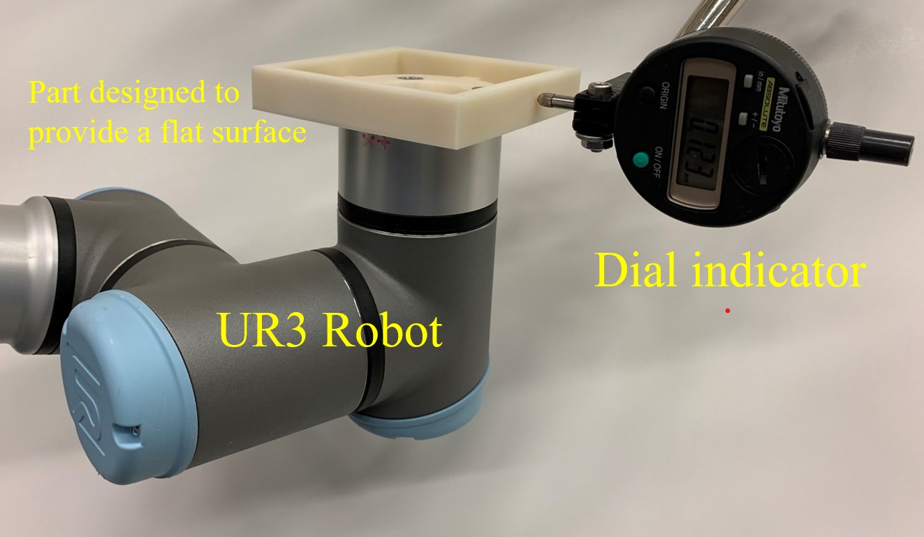
We used a UR3 robot to provide precise motions of the helmet. We first verified the measurement accuracy of the UR3 robot, for a 10 mm range of motion, using a dial indicator (543-693B, Mitutoyo Corp., Japan), as shown in Fig. 5. We limit the robot motion to this specific range since the designed clearance between the helmet and the imaging ring is only about 15 mm, as outlined in Section II-A. Table II summarizes the result of the verification. The difference indicated in the third column could have been partially caused by the rough surface on the 3D-printed part that was mounted on the UR3 end-effector. Nevertheless, we can conclude that the UR3 accuracy is about 0.1 mm, and hence precise enough to provide the ground-truth helmet motion in our experiments.
| Robot | Dial Indicator | Difference |
|---|---|---|
| -10 | -9.880 | -0.120 |
| -9 | -8.884 | -0.116 |
| -8 | -7.898 | -0.102 |
| -7 | -6.912 | -0.088 |
| -6 | -5.911 | -0.089 |
| -5 | -4.914 | -0.086 |
| -4 | -3.950 | -0.050 |
| -3 | -2.951 | -0.049 |
| -2 | -1.946 | -0.054 |
| -1 | -0.956 | -0.044 |
| 0 | 0.004 | -0.004 |
| 1 | 0.966 | 0.034 |
| 2 | 1.956 | 0.044 |
| 3 | 2.956 | 0.044 |
| 4 | 3.923 | 0.077 |
| 5 | 4.925 | 0.075 |
| 6 | 5.909 | 0.091 |
| 7 | 6.913 | 0.087 |
| 8 | 7.899 | 0.101 |
| 9 | 8.881 | 0.119 |
| 10 | 9.874 | 0.126 |
III-B Calibration results
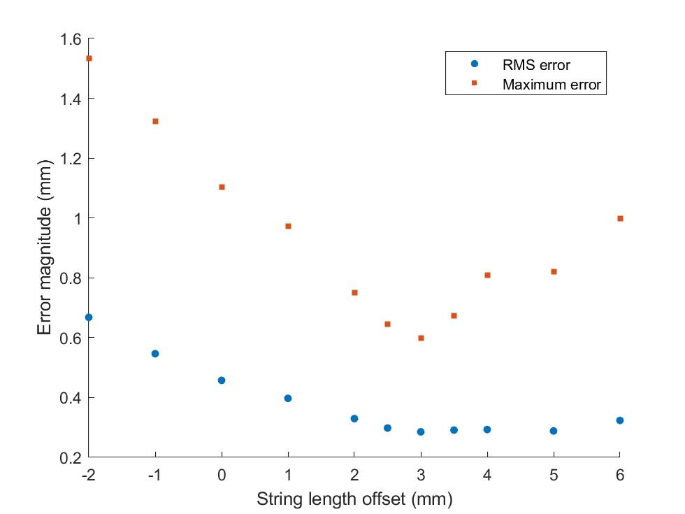
For each string length offset, we obtained the vector difference between the displacement measured by the string encoder system, , and the actual displacement produced by the UR3 robot, , at each of the 66 points. We then took the norm of these error vectors, , obtained the root-mean-square (RMS) as well as the maximum across all 66 points, and plotted them against the respective offset, as shown in Fig. 6. All offsets from 2.5 mm to 5 mm share similar RMS error magnitudes of around 0.3 mm, but the 3 mm offset is shown to have the smallest maximum error magnitude.
We also used calipers to measure the string outer diameter, which was 0.8 mm, and the inner diameter of its guide channel, which was 2.8 mm, giving a clearance of 1 mm. A similar phenomenon is also present on the moving end of the encoder attached on the helmet, where the position of the string is also shifted by about 1 mm. Additionally, we observed the difference in the encoder readings before and after temporarily holding one string at the two designated attachment points using tools, and noted that the string length reading increased by 2.5 mm. Therefore, our selection of the 3 mm offset based on error minimization is supported by physical measurement, and this value is used in the subsequent accuracy evaluation.
III-C Accuracy evaluation
We first determined the transformation between the UR3 robot coordinate system and the string encoder coordinate system, as described in Section II-F. Then, the UR3 robot performed a range of motion of 10 mm or deg along each of the axes, one axis at a time, in increments of 1 mm or deg. At each position, the string lengths were recorded, adjusted by the 3 mm string length offset identified above, and then the forward kinematics applied to compute the Cartesian position. The results are shown in Table III as well as in Fig. 7.
| Displacement | (mm) | |||||
|---|---|---|---|---|---|---|
| (mm or deg) | X | Y | Z | Roll | Pitch | Yaw |
| -10 | 0.340 | 0.438 | 0.176 | 0.090 | 0.569 | 0.462 |
| -9 | 0.222 | 0.379 | 0.109 | 0.207 | 0.652 | 0.460 |
| -8 | 0.208 | 0.301 | 0.156 | 0.178 | 0.519 | 0.397 |
| -7 | 0.265 | 0.275 | 0.165 | 0.210 | 0.425 | 0.428 |
| -6 | 0.116 | 0.219 | 0.227 | 0.194 | 0.433 | 0.460 |
| -5 | 0.161 | 0.165 | 0.242 | 0.189 | 0.294 | 0.316 |
| -4 | 0.121 | 0.146 | 0.254 | 0.162 | 0.255 | 0.258 |
| -3 | 0.054 | 0.139 | 0.232 | 0.175 | 0.161 | 0.265 |
| -2 | 0.129 | 0.023 | 0.108 | 0.143 | 0.164 | 0.213 |
| -1 | 0.030 | 0.121 | 0.040 | 0.075 | 0.103 | 0.173 |
| 0 | 0.068 | 0.045 | 0.111 | 0.115 | 0.111 | 0.018 |
| 1 | 0.198 | 0.126 | 0.126 | 0.033 | 0.159 | 0.061 |
| 2 | 0.138 | 0.126 | 0.035 | 0.059 | 0.216 | 0.030 |
| 3 | 0.127 | 0.118 | 0.108 | 0.106 | 0.382 | 0.215 |
| 4 | 0.199 | 0.201 | 0.056 | 0.161 | 0.421 | 0.252 |
| 5 | 0.264 | 0.270 | 0.204 | 0.208 | 0.526 | 0.250 |
| 6 | 0.260 | 0.225 | 0.179 | 0.287 | 0.663 | 0.323 |
| 7 | 0.272 | 0.323 | 0.240 | 0.336 | 0.758 | 0.494 |
| 8 | 0.357 | 0.342 | 0.238 | 0.408 | 0.792 | 0.556 |
| 9 | 0.363 | 0.375 | 0.324 | 0.451 | 0.968 | 0.574 |
| 10 | 0.394 | 0.425 | 0.333 | 0.522 | 1.003 | 0.734 |
| RMS | 0.223 | 0.257 | 0.193 | 0.241 | 0.529 | 0.377 |
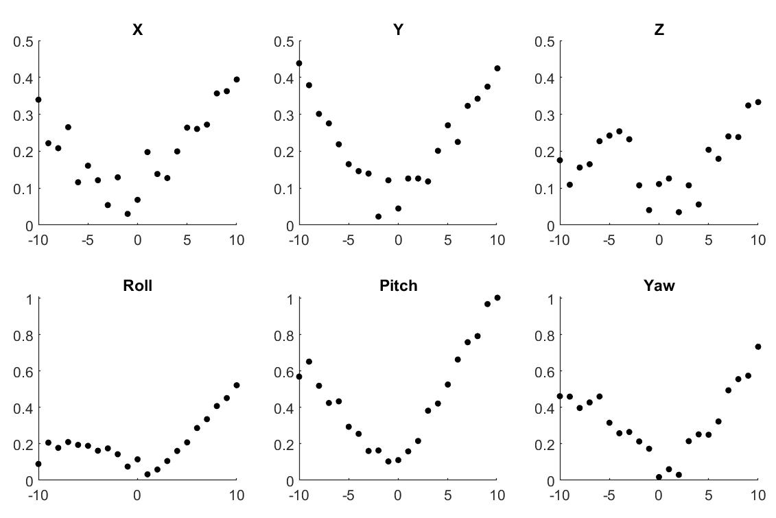
The results indicate that we have achieved RMS errors less than 0.3 mm for translations along all three axes, and for rotation around the z-axis, and less than 0.6 mm for the other two rotations. For the translations, even the maximum error magnitude within the 10 mm motion range was less than the 0.5 mm requirement for fine motion correction.
IV Conclusions
We developed a mechanical 6 DOF measurement system consisting of 6 parallel string encoders, connected in a Stewart platform configuration. This system is intended to be used to measure the motion of a helmet, worn by a human subject, with respect to a PET imaging ring supported by a robotic system. We performed experiments, using a robot to provide precise helmet motions, and verified that RMS translation errors are usually less than 0.3 mm, with values slightly above 0.5 mm for some rotations. These relatively larger errors associated with displacements in the pitch and yaw angles might be attributed to inaccuracy in setting the robot TCP, a process mentioned in section II-F. Since the TCP is set to be a constant offset in the direction (Z) perpendicular to the mounting surface of the robot end effector, an inaccuracy in setting this offset would cause robot rotations about the tool X and Y axes (yaw and pitch, respectively) to also cause translations that would be measured by the string encoder system. Nonetheless, the performance described above is sufficient for coarse motion correction, where a robot moves the PET imaging ring to attempt to keep it centered around the head. It may be suitable for fine motion correction, performed during image reconstruction, where an accuracy of 0.5 mm or better is desired.
Our testing only evaluated one motion axis at a time—it is possible that combined motions (e.g., simultaneous translation and rotation) would produce higher errors. We have not yet identified a specification for the largest rotation error and our testing did not measure the rotation error (we only measured the translation error resulting from applied rotations). Considering that the maximum radius of a human head is about 100 mm, a rotation error of 0.3 degrees would produce an error of about 0.5 mm on the skull surface. However, for neuroscience research, targets of interest will likely be closer to the center of the head and therefore the effect of rotation error may be less critical. Our future work includes determination of the rotation accuracy specification for fine motion correction. In addition, if the UR5 robot is able to keep up with the head motion, the relative displacement of the head with respect to the imaging ring may be much smaller than the 10 mm and 10 degree displacements tested here. In that case, we could expect higher accuracy as our results indicate higher accuracy for displacements closer to the center position. If necessary, we can perform a kinematic calibration of the string encoder system using methods developed for Stewart platforms [14] to further increase the accuracy.
Our next stage of development will be to use the UR3 robot to emulate realistic human head motion, using the previously recorded data analyzed in our prior work [8], and to use the UR5 robot to move the PET imaging ring based on those measurements. Eventually, since the PET imaging ring can weigh up to 20 kg and the UR5 has a payload of only 5 kg, the UR5 would be replaced by a custom robot, but currently it serves as a prototype for verification of our motion measurement and compensation system.
Acknowledgements
Yangzhe Liu participated in early design discussions of the measurement system.
References
- [1] S. Majewski, J. Proffitt, J. Brefczynski-Lewis, A. Stolin, A. Weisenberger, W. Xi, and R. Wojcik, “HelmetPET: A silicon photomultiplier based wearable brain imager,” in IEEE Nuclear Science Symposium and Medical Imaging Conference Record, Valencia, Spain, Oct. 2011, pp. 4030–4034.
- [2] S. Majewski, “The path to the “ideal” brain PET imager: The race is on, the role for TOF PET,” Il Nuovo Cimento C, vol. 43, no. 1, pp. 1–35, 2020.
- [3] O. V. Olesen, “Markerless 3D head tracking for motion correction in high resolution PET brain imaging,” Ph.D. dissertation, Technical University of Denmark, 2011.
- [4] O. V. Olesen, J. M. Sullivan, T. Mulnix, R. R. Paulsen, L. Højgaard, B. Roed, R. E. Carson, E. D. Morris, and R. Larsen, “List-mode PET motion correction using markerless head tracking: Proof-of-concept with scans of human subject,” IEEE Transactions on Medical Imaging, vol. 32, no. 2, pp. 200–209, 2013.
- [5] A. Z. Kyme, S. Se, S. R. Meikle, and R. R. Fulton, “Markerless motion estimation for motion compensated clinical brain imaging,” Physics in Medicine & Biology, 2018.
- [6] S. Anishchenko, D. Beylin, A. Stepanov, I. Weinberg, S. Schaefer, V. Zavarzin, D. Shaposhnikov, and M. Smith, “Evaluation of a video-based head motion tracking system for dedicated brain PET,” Medical Imaging 2015: Physics of Medical Imaging, 2015.
- [7] M. Chamberland, R. Wassenaar, B. Spencer, and T. Xu, “Performance evaluation of real-time motion tracking using positron emission fiducial markers,” Medical Physics, vol. 38, no. 2, pp. 810–819, 2011.
- [8] Y. Liu, T. Wu, I. I. Iordachita, C. Paquette, and P. Kazanzides, “Analysis of human head motion and robotic compensation for PET imaging studies,” in IEEE Engineering in Medicine & Biology Conf. (EMBC), 2021, pp. 4836–4839.
- [9] D. Lau, J. Eden, Y. Tan, and D. Oetomo, “CASPR: A comprehensive cable-robot analysis and simulation platform for the research of cable-driven parallel robots,” in IEEE Intl. Conf. on Intelligent Robots and Systems (IROS), Nov. 2016, pp. 3004–3011.
- [10] J. W. Jeong, S. H. Kim, Y. K. Kwak, and C. C. Smith, “Development of a parallel wire mechanism for measuring position and orientation of a robot end-effector,” Mechatronics, vol. 8, no. 8, pp. 845–861, Dec. 1998.
- [11] J.-P. Merlet, Parallel Robots. Springer, 2006.
- [12] K. Harib and K. Srinivasan, “Kinematic and dynamic analysis of Stewart platform-based machine tool structures,” Robotica, vol. 21, pp. 541–554, 2003.
- [13] P. Kazanzides, Z. Chen, A. Deguet, G. S. Fischer, R. H. Taylor, and S. P. DiMaio, “An open-source research kit for the da Vinci® surgical system,” in IEEE Intl. Conf. on Robotics and Auto. (ICRA), Hong Kong, China, Jun 2014, pp. 6434–6439.
- [14] H. Zhuang, O. Masory, and J. Yan, “Kinematic calibration of a Stewart platform using pose measurements obtained by a single theodolite,” in IEEE/RSJ Intl. Conf. on Intelligent Robots and Systems (IROS), 1995, pp. 329–334.