Quantum trapping and rotational self-alignment in triangular Casimir microcavities
Abstract
Casimir torque –- a rotational motion caused by the minimization of the zero-point energy –- is a problem that attracts significant theoretical and experimental interest. Recently, it has been realized using liquid crystal phases and natural anisotropic substrates. However, for natural materials, the torque reaches substantial values only at van der Waals distances of nm. Here, we employ Casimir self-assembly using templated gold nanostructures of triangular symmetry for the purpose of rotational self-alignment at truly Casimir distances (100 – 200 nm separation). The joint action of repulsive electrostatic and attractive Casimir potentials leads to the formation of a stable quantum trap, giving rise to a tunable Fabry-Pérot microcavity. This cavity self-aligns both laterally and rotationally to maximize the overlap area between the templated and floating triangular flakes. The rotational self-alignment is remarkably sensitive to the equilibrium distance between the two triangles as well as their area, which opens possibilities for active control through manipulating the electrostatic screening. Our self-assembled and self-aligned Casimir microcavities could find future use as a versatile and tunable platform for nanophotonic, polaritonic, and optomechanical applications.
KEYWORDS: Casimir effect, self-assembly, self-alignment, quantum trapping, templated micro- and nano-cavities.
I Introduction
The quantum nature of van der Waals forces was initially revealed by London London (1937) and subsequently generalized by Casimir and Polder Casimir and Polder (1948). Furthermore, Casimir extended this concept to describe the attraction between two ideal mirrors Casimir (1948), which brought a quantum electrodynamics effect to the macroscopic scale. Following this, Lifshitz and co-authors developed a theory that allowed for the calculation of the Casimir effect between arbitrary planar mirrors, relying on the classical optical response of materials Lifshitz (1956); Dzyaloshinskii et al. (1961). This advancement paved the way for predicting both repulsive Munday et al. (2009); Munday and Capasso (2010) and lateral Casimir forces Chen et al. (2002a, b); Rodrigues et al. (2006) in various contexts.
The introduction of asymmetry allows extending the Casimir effect to a new degree of freedom – rotation. In this respect, Casimir torque led by quantum fluctuations was first predicted by Kats Kats (1971) and Parsegian and Weiss Parsegian and Weiss (1972) when considering dielectric media with in-plane anisotropy at short separation distances. Later, the approach was generalized to longer distances by Barash s. Barash (1978). However, the predicted torque was small and turned out to be challenging to observe. The first Casimir torque measurements were reported only recently Somers et al. (2018); Spreng et al. (2022). In these measurements, the air gap was replaced with a solid isotropic interlayer, which helped support two anisotropic materials at a fixed distance and in a parallel configuration. The torque was measured by optical characterization of the twist of a liquid crystal, which acted as one of the birefringent bodies. Such a setup allowed controlling the sign and strength of the torque by choosing an anisotropic substrate material and varying the interlayer thickness, but did not allow to observe the torque directly, since the rotation was hidden inside the liquid crystal. Furthermore, the torque between two media with artificial in-plane anisotropy, such as lamellar gratings, was predicted to be substantially greater than in natural anisotropic materials Guérout et al. (2015); Antezza et al. (2020). Particularly, Guerout et al. Guérout et al. (2015) obtained the torque per unit area for the infinite gratings and accounted for the finite-size effects using the overlap area approximation, which works well when the lateral size of the gratings is much larger than their characteristic length scales and the gap between them. Recently, Antezza et al. Antezza et al. (2020) calculated the Casimir torque between finite-sized metallic gratings beyond the overlap approximation. It turned out that a finite number of gratings periods leads not only to oscillations of the torque direction but also to a much larger magnitude of the torque than intuitively expected. Moreover, due to a critical zero-order geometric transition between a 2D- and a 1D-periodic system, the torque per unit area can reach extremely large values, increasing without bounds with the size of the system, which paves the way to observation of the torques at truly Casimir distances 100 nm and beyond.
Importantly, an alternative way to observe Casimir torques is offered by the optical levitation of anisotropic dielectric nanoparticles (silica in particular) in vacuum Xu and Li (2017); Ahn et al. (2018, 2020). This method has ultra-high sensitivity but requires high vacuum conditions and works only with relatively small nanoparticles that can be captured using conventional optical tweezers. Therefore, this method does not allow direct imaging of the Casimir torque in an optical microscope but instead relies on polarization-dependent readout.
We note that the aforementioned works primarily focus on Casimir interactions in dry or vacuum environments. However, the introduction of liquids can be beneficial – in particular, repulsive Casimir forces have been successfully demonstrated using a combination of high refractive index liquid bromobenzene interfaced between two solids – gold and glass substrates Munday et al. (2009), as well as in gold-ethanol-teflon systems Zhao et al. (2019). Furthermore, the liquid environment allows to use colloids as a platform for studying Casimir interactions. The theoretical framework for describing colloidal interactions in solution is often based on the DLVO theory, which typically involves electrostatic stabilization to balance attractive van der Waals forces Derjaguin and Landau (1941); Verwey (1947). Recently, the DLVO theory has been extended to account for retardation effects Biggs and Mulvaney (1994); Munkhbat et al. (2021).
Van der Waals and Casimir interactions in colloidal solutions play an important role not only in their stability but also in self-assembly Whitesides and Grzybowski (2002); Cho et al. (2007); Batista et al. (2015); Zhao et al. (2019); Esteso et al. (2019); Ge et al. (2020); Schmidt et al. (2023). Recently, the formation of self-assembled, stable Fabry-Pérot (FP) cavities has been achieved through a combination of attractive Casimir and repulsive electrostatic interactions Munkhbat et al. (2021). This development opens up new possibilities for strong light-matter interactions and highlights the intrinsic relationship between the original Casimir problem and the planar microcavity problem. Moreover, the electrostatic force in the system can be actively modified, enabling the tuning of the FP resonance within a certain range without compromising cavity stability. The repulsive electrostatic force in the Casimir microcavity can be controlled by adjusting the ion concentration of the aqueous solution. This delicate balance between the attractive Casimir force and the repulsive electrostatic force not only stabilizes the FP cavity in the vertical direction but also enables the formation of laterally stable structures.
The Casimir self-assembly approach offers numerous advantages, but it also presents certain challenges. These challenges include slow diffusion-limited cavity formation, irreproducibility, unscalable fabrication, and a lack of integration with microfluidics. One potential solution to address these challenges is the use of templated structures. Indeed, substrates that are templated with various nanostructured patterns are commonly employed in self-assembled colloidal systems and plasmonic arrays Rycenga et al. (2009); Zhou et al. (2014); Hanske et al. (2014); Scarabelli et al. (2021). Implementing this approach could help overcome several problematic issues on the road towards realizing asymmetry-induced Casimir torques in liquid environments and scalable as well as stable formation of Casimir microcavities in vertical, horizontal, and rotational domains. However, to date, the templated self-assembly approach has not been explored for Casimir self-assembly and Casimir torques.
Here, we introduce template-assisted systems for the self-assembly of Casimir microcavities, where patterned metallic surfaces on the substrate are crucial for achieving lateral Casimir forces and self-alignment through Casimir torque. We specifically chose an equilateral triangle geometry to realize the Casimir torque, as triangles’ symmetry provides the highest possible torque among other equilateral microstructures. We investigate the self-alignment of triangular nanoflakes in an aqueous solution at room temperature by monitoring the rotational motion induced by the lateral Casimir force, which strives to maximize the overlap area between the top colloidal flake and the bottom templated flake on the substrate. This rotational effect is significant and can be observed in real time using an optical microscope. Additionally, we study the influence of thermal fluctuations, the separation distance between the flakes, and their areas on the stability of the obtained microcavities. Our approach not only enables the scalability of the Casimir self-assembly and self-alignment but also paves the way for the integration of Casimir torque effects with colloidal science, nanophotonics, polaritonics, and self-assembly. On a broader account, it is important to mention that Casimir and Casimir torque effects studied here could be relevant for the design of micro-electromechanical devices Chan et al. (2001) and in future devices relying on an efficient and contactless transfer of angular momentum Sanders et al. (2019); Ashourvan et al. (2007); Lombardo et al. (2008); Cavero-Peláez et al. (2008).
II Results and Discussion
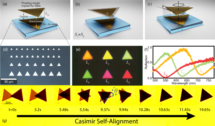
The process of formation of stable Casimir microcavities in aqueous solution Munkhbat et al. (2021) can be significantly enhanced and more accurately controlled by combining top-down nanopatterned gold areas (referred to as “seeds”) on the glass substrate and floating Au flakes in the solution (Fig. 1a). This approach allows to control the density, size, and shape of the seeds, which is unavailable for the previous method. Over time, the floating Au flakes, playing the role of “micromirrors”, diffuse towards the seeds and form dimers due to lateral Casimir forces. Moreover, if the seeds are triangular, the floating flakes not only form stable cavities but also geometrically align with the seeds to maximize the overlap area (and hence minimize the Casimir potential, see Fig. 1c).
In this work, we focus specifically on equilateral triangles (Fig. 1a). Experiments are designed with two main components: (i) glass substrates with the precisely fabricated seeds produced by electron beam lithography (EBL), and (ii) single crystal Au flakes in aqueous solution produced by wet chemical synthesis ani (2006). Triangular Au seeds with lateral dimensions in the 4 – 10 m range and 20 nm heights are shown in Fig. 1d (also see Methods). The seed approach allows us to control the Casimir force on the floating Au flake. Since it is difficult to control the colloidal growth with high precision ani (2006), chemically synthesized Au flakes are typically obtained in a range of sizes, thicknesses, and shapes. To simplify the self-alignment problem, we therefore preselect only equilateral triangle flakes of appropriate size by dragging them with optical tweezers to the seeds.
Stable dimers emerge as a result of the equilibrium between two opposing forces, the attractive Casimir force and the repulsive electrostatic force, occurring at a specific distance denoted as . Furthermore, these dimers support optical Fabry-Pérot (FP) resonances that can be modified by controlling . This is illustrated in Fig. 1e, where variations in the reflected light’s color are depicted for different values. The corresponding reflection spectra, as shown in Fig. 1f, serve as the basis for the experimental determination of (see Methods). The variation of not only impacts the FP resonance but also significantly influences the Casimir potential, which scales approximately as for 30 nm thick Au flakes Munkhbat et al. (2021). The manipulation of can be achieved by adjusting the total ion concentration in the solution, due to altering the Debye-Hückel screening length of electrostatic repulsion, described by (see Methods, Eq. 4). Furthermore, the engineering of geometric patterns on the substrate allows to employ diverse sizes of triangular Au seeds and flakes (Fig. 1d). This approach facilitates an investigation into the influence of overlap areas on the lateral Casimir force (Fig. 1b).
A specific example of Casimir self-alignment, depicted in Fig. 1g, demonstrates the nearly isolated nature of two distinct motions: lateral and rotational (Supplementary Video 3), enabling their separate analysis. Throughout the self-assembly and self-alignment process, the floating Au flake initially exhibits predominantly lateral motion, moving towards the Au seed with minimal rotation. This lateral shift aims to increase the overlap area. Subsequently, in the second phase, the floating flake begins to rotate, ultimately achieving full overlap with the seed. It is intriguing to observe the individual contributions of these two motions to the overall increase in the overlap area and eventually forming a stable dimer (see Supplementary Videos 1-3).
In what follows, we analyze both, the dimer formation process and the stability of the self-assembled dimers to thermal fluctuations. Furthermore, by employing the seed concept, the system’s behavior can be controlled by both and the total area of the Au seeds. The forthcoming sections provide a detailed exploration of how both of these parameters impact the Casimir potential, the dimer formation, the self-alignment process, and the robustness of these alignments to thermal fluctuations.
II.1 Accelerated dimer formation by lateral and rotational Casimir forces
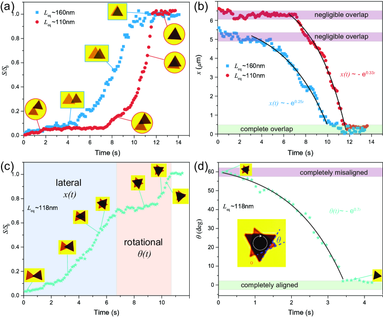
Previously, we elucidated the advantages of employing the seed approach for achieving lateral motion and enhancing stability in lateral alignment with the corresponding seed. In this section, we additionally note that the lateral motion of the flake exhibits varying speeds during the dimer formation with the seed. This phenomenon is especially evident when the floating flake approaches the seed with the same orientation. The lateral Casimir force draws the floating flake towards the Au seed, which causes a concurrent increase in the overlap area between the flake and the seed, . When the initial orientations of the triangles match, dimer formation occurs without any rotational motion, simplifying the observation of lateral motion acceleration as well as alterations in acceleration with increasing overlap area. This process is evidenced in Fig. 2. Initially, when the overlap area is minimal, the flake’s motion is slow and of predominantly Brownian nature. Over time, the seed exerts a robust attraction on the floating flake, eventually leading to full area overlap, . The lateral and rotational motions stop when the two triangles achieve perfect overlap and alignment. Our data analysis involves extracting the overlap area of the seed and Au flake from each frame of the videos (Supplementary Videos 1 and 2) and normalizing it with the total area of the seed (or floating flake) – , as depicted in Fig. 2a.
Since the separation distance is intricately linked to the Casimir potential, the acceleration of the Au flake exhibits a direct dependence on . This is demonstrated in Fig. 2a, where we present for two distinct values. It is important to highlight the critical role played by , given its strong influence on the lateral Casimir forces – even slight alterations in yield a substantial impact on the acceleration dynamics of the Au flake. The inset pictures correspond to video frames depicting the exemplary data points. Furthermore, we calculate the position changes over time by tracing the displacement of the center of mass of the floating flake with respect to that of the seed, .
Due to the viscous friction in the liquid and the small mass of the flake, the motion under the lateral Casimir force in our case occurs deeply in the overdamped regime. In this regime, the flake’s mass is negligible, and the lateral (and rotational) motion takes place on a time scale of seconds, leading to the appearance of exponentially decaying function , where is a characteristic effective frequency. Notably, the signs before and inside this exponent result from the non-harmonic nature of the lateral overlap potential. In a harmonic case, the decaying solution exhibits the opposite curvature (see Supplementary Theory). The effective frequency 1 Hz is determined by the total potential per unit area (with Casimir and electrostatic contributions) and the lateral diffusion coefficient . These contributions distinctly depend on . Specifically, the absolute value of the total potential grows with a decrease in as follows: , where and are distance-independent constants of the electrostatic and Casimir potentials, is the Debye–Hückel screening length, and is the Casimir potential power law for 30 nm thick Au flakes Munkhbat et al. (2021). On the contrary, the lateral diffusion coefficient decreases with a decrease in as . However, according to previous hydrodynamic simulations, it exhibits a slower dependence with distance, with Schmidt et al. (2023). Consequently, the effective frequency is expected to increase with a decrease in , so the lateral motion occurs faster when is smaller, as clearly illustrated by the exponential fits depicted in Fig. 2b.
In Fig. 2c, we employ the same method as in Fig. 2a but for a different dimer configuration. As depicted in the plot, lateral motion plays a dominant role until 7 s mark, at which point the floating flake is found exactly on top of the seed but with an opposing orientation (). From that point on, the rotational motion becomes dominant, causing the floating flake to rotate around the vertical axis under the influence of the Casimir torque until it achieves full alignment (see Supplementary Video 3). Since the lateral motion becomes negligible after the first 7 s, we find it reasonable to analyze solely rotational motion by tracking changes in over time, as depicted in Fig. 2d. Similar to the lateral displacements, this rotational motion conforms to an exponential decay function with an effective Hz frequency (see Supplementary Theory), starting from a state of complete misalignment () and culminating in a state of perfect alignment ().
Thus, our method results in the precise positioning (trapping) of floating Au flakes within three-dimensional space, offering control over their vertical, horizontal, and rotational orientations. This unique quantum trapping approach harnesses quantum vacuum fluctuations, rather than real fields (as in e.g. optical tweezing), for particle manipulation Zhao et al. (2019); Munkhbat et al. (2021). Despite the inherent influence of thermal fluctuations, the trapping potential created by the Casimir effect exhibits remarkable stability, enabling controlled particle confinement. In the subsequent sections, we delve into an in-depth investigation of thermal fluctuations, specifically focusing on their magnitude and the resulting particle displacement, especially concerning rotational motion around the vertical axis.
II.2 Calculation of the lateral and rotational Casimir effect between two triangular flakes
To improve our understanding of the observed phenomenon and confirm its primary association with the Casimir effect, we conducted both analytical and numerical computations focusing on the in-plane motion of flat triangular Au flakes induced by vacuum fluctuations. The analytical calculations were performed using the Lifshitz formalism Lifshitz (1956); Dzyaloshinskii et al. (1961) and involved several critical approximations to model the underlying dynamics.
First, the Casimir-Lifshitz potential per unit area for the system comprising two identical infinite Au planar mirrors immersed in an aqueous solution and separated by a gap of thickness was calculated using the following expression:
| (1) |
where the integration was performed over the imaginary frequencies , normalized by the speed of light , and the wave vector components along the mirrors . The summation involved both p- and s-polarizations. Here, are the Fresnel reflection coefficients for the gold plates evaluated at various wave vectors and mirror thicknesses . The dielectric functions of gold and water were evaluated at the imaginary frequencies.
Second, to account for the shape and size of the floating flakes and seeds, we employed the overlap approximation. This approximation assumes that the Casimir-Lifshitz potential is proportional to the overlap area between the flake and the seed while neglecting any edge effects. In this approach, the lateral potential can be expressed as follows:
| (2) |
where are the in-plane displacements, is the in-plane rotation angle, is the overlap area between the flake and the seed, and is the Casimir-Lifshitz potential per unit area evaluated at .
Third, we assume that the lateral displacements (along or ) and rotations (around by angle ) are independent of each other, allowing for factorization. Consequently, we arrive at simplified forms for the potentials: for lateral displacement (along ) and for rotation. In our experiments, we focused on equilateral triangles, where the corresponding overlap areas are expressed as follows:
| (3) |
where is the area of an equilateral triangle with the edge . Lateral Casimir forces and Casimir torques can be obtained by differentiating and , correspondingly, along their respective motions (see Supplementary Theory).
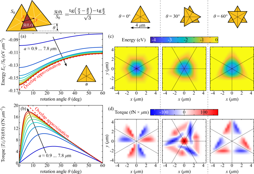
To assess the significance of the edge effects, we conducted a comparative analysis between the analytical calculations within the overlap approximation and numerical simulations using SCUFF-EM Reid et al. (2009); SCU . Specifically, we simulated the relative rotation and in-plane translation of two vertically trapped Au equilateral triangles immersed in an aqueous solution, where the Casimir and electrostatic forces at are balanced. Figure 3 presents the simulation results alongside analytical calculations. Due to the symmetry of the equilateral triangles, we considered rotation angles ranging from to . Examining the rotational dependence of the Casimir energy normalized to the corresponding triangle surface area at zero and displacements, it is evident that the numerical curve approaches the analytical approximation as the triangle size increases. For triangles with m , the overlap approximation performs exceptionally well for (Fig. 3a). As mentioned earlier and detailed in Supplementary Materials, the lateral Casimir potential has a non-harmonic shape in the overlap approximation. However, at small angles, the edge effects captured by SCUFF-EM simulations become prominent, resulting in a quasi-harmonic potential, as shown in Fig. 3a. This effect is even more pronounced for the Casimir torque, normalized to the overlap area (Fig. 3b). Here, the overlap approximation performs well at . However, at small angles, the edge effects become significant. Importantly, the torque cannot surpass the limit set by the overlap approximation at any angle. Furthermore, the torque reaches its maximum at an angle where an optimal balance between edge effects and increased overlap area is attained. With increasing triangle size, the role of edge effects diminishes, causing the optimal angle to decrease, and eventually approach zero for infinite triangles. Notably, unlike the anisotropic finite-sized systems considered by Antezza et al. Antezza et al. (2020), we observe high accuracy of the overlap approximation for large triangles owing to their isotropy.
For non-zero in-plane displacements of the triangles, the discussed phenomena become even more intricate. Figures 3c,d show the combined influence of translation and rotation on the Casimir energy and torque, respectively. The energy’s dependence on displacements consistently reaches a minimum in the center at (Fig. 3c), corresponding to the stable configuration of the system and the lateral Casimir trapping. As rotation is introduced (), the energy colormap undergoes a shape transition from hexagon to triangle forms, although this does not lead to qualitative changes. The role of rotation is evident in the torque colormaps (Fig. 3d). For a non-zero rotation angle, in the region of zero displacements, a pronounced spot of maximum torque emerges, aligning with the earlier discussed scenario of rotation at zero displacements. Remarkably, even at zero rotation, the interplay between the system’s geometry and relative displacements may lead to non-vanishing torques. This effect disappears on the symmetry axes of the rotated triangle, having different signs on opposite sides of these axes. Additionally, at , the rotated system becomes so symmetric that the torque is entirely compensated in the large area around zero displacements. For all intermediate angles (additional data shown in Supplementary Material) between and , a mixed pattern emerges, with maximum torque at the center, surrounded by areas of effective torque induced by displacements and rotations. These areas deviate from the symmetry axes of the rotated triangle but maintain alternating torque signs around the central maximum. Consequently, as the flake moves with simultaneous displacement and rotation, additional torque in the opposing direction may arise, resulting in a crawling-like motion.
II.3 Impact of equilibrium distance, seed area, and thermal fluctuations on stability of Casimir self-alignment
The self-alignment experiments are conducted in the range spanning 100 – 200 nm, where conditions allow establishing a stable equilibrium and a sufficiently deep trapping potential. In each self-alignment measurement, is precisely determined by assessing the reflection spectrum of the stable FP microcavity, Fig. 1f, and subsequently fitting the spectrum using the transfer-matrix method (see Methods).
To investigate the impact of on self-alignment, we maintain a fixed seed size, m, while choosing a floating flake that matches this seed size. Optical tweezers are employed to bring the flake into close proximity with the seed, and then allow it to freely diffuse until the Casimir potential ensures the formation of a stable dimer. Subsequently, we track the dynamics of the angle between the triangles over time, . When , the floating Au flake perfectly aligns with the seed, and the Casimir potential is minimized, thus corresponding to the equilibrium position, as illustrated in Fig. 3a.
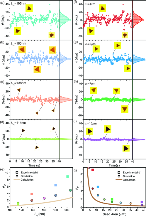
Figures 4a-d illustrate the variations in for four distinct values: 206 nm, 180 nm, 138 nm, and 114 nm, respectively, as a result of thermal fluctuations. Specifically, in Fig. 4a, the fluctuations in are the strongest among situations presented in Fig. 4. This is attributed to the fact that at this , the thermal energy () approaches the depth of the trapping potential, leading to more pronounced deviations in from its equilibrium position due to thermal fluctuations. As a result, the floating flake exhibits fluctuations of up to 20∘ at different points in time (see distributions and standard deviations to the right of the corresponding plots).
Importantly, the fluctuations of decrease upon reduction in . To demonstrate that, we fit the experimental histograms of to the normal distribution functions, and find that the variances, denoted as , grow with , as depicted in Fig. 4e. The reason for this lies in the steep dependence of the trapping Casimir potential on the distance, Munkhbat et al. (2021) as discussed above. Furthermore, we determine theoretically by substituting the analytical Casimir-Lifshitz potential from Eq. (1) into the equation for the mean square displacement using Gibbs formalism (see Methods, Eq. 5). Combined with the overlap approximation and the Casimir potential from SCUFF-EM simulations, we arrive at results that are qualitatively similar to experimental observations. Our theoretical results are especially close to the experimental findings at small , however, they underestimate approximately 2-fold (for SCUFF-EM simulations) at large . This discrepancy can be attributed to electrostatics, which was not included in our calculations and modeling, given its relatively weak contribution compared to Casimir forces. Indeed, the relative contribution of the electrostatic part to the total potential increases with , contributing to the growing mismatch at large separations. Furthermore, the difference between the analytical and numerical results reflects the significance of the edge effects, especially at small deviations from equilibrium. Additionally, the accuracy of the overlap approximation not only increases with the size of the flakes (), as we discussed earlier, but also with a decrease in . In other words, the analytical approximation’s accuracy increases with the ratio . Finally, it is important to note that at small displacements ( and ), the Casimir torques (and hence ) are almost independent of displacements (see Fig. 3d), justifying our analysis.
The magnitude of the trapping potential scales with the area overlap of the seed and the floating Au flake. This is a fundamental reason for the rotational self-alignment observation in the seed configuration – Au flakes in the aqueous solution strive to maximize their overlap areas with the seeds due to strong Casimir attraction. As previously, we preselect the flakes such that they match the shape and size of the corresponding seed, which simplifies experiments and allows for precise tracking of the rotational motion of the floating flake (see Supplementary Video 4).
In the subsequent study, we probe the stability of the trapping potential to thermal fluctuations for a fixed 195 nm, as a function of the total area of the seed, (Fig. 1b). We specifically investigate four different seed sizes in the range between 4 and 10 m, depicted in Fig. 4f-i. As expected from the Casimir energy calculations (see Fig. 3a), increasing the area of Au seeds increases the Casimir energy (and the depth of the trapping potential), which results in more stable microcavities.
The stability dependence on the overlap area is shown in Fig. 4f-i by plotting the dynamics of caused by thermal fluctuations for 4, 5, 7, and 10 m triangle seed sizes. The standard deviations, , obtained from fits of histograms to the normal distribution function, indicate that the stability strongly depends on the area overlap. In particular, the biggest flakes display the most pronounced stability – i.e. the stability is inversely proportional to the flake area, or more accurately, . This aligns with the analytical calculations and numerical simulations discussed in the previous paragraphs. However, in this case, the difference between the calculations and measurements remains consistent across different overlap areas. This further validates that the discrepancy is indeed caused by the contribution of the electrostatic potential. These results demonstrate that control of lateral stability of the FP cavity can be achieved by selecting various seed sizes while maintaining the same separation distance (see Supplementary Video 5).
III Conclusion
In conclusion, vertically and laterally stable self-assembled and rotationally self-aligned Casimir microcavities can be formed by equilibrating two opposing forces: attractive Casimir and repulsive electrostatic. The so-formed microcavities exhibit optical Fabry-Pérot resonances in the visible spectral range, observed as pronounced reflection colors. Control of the self-alignment of the cavity is demonstrated by using triangular templated substrates and is studied upon variation of two independent parameters: (i) the equilibrium distance, , between the floating flake and the templated substrate, and (ii) the flake area, , by varying the seed and the floating flake sizes. These two parameters are straightforward to control. Therefore, our method offers flexibility to achieve the desired conditions for liquid-phase Casimir torque experiments. Furthermore, we investigated the stability of self-alignment to thermal fluctuations, which was assessed by examining as a function of and . We find that our experimental observations are in good agreement with Casimir-Lifshitz theory and with SCUFF-EM numerical modeling. This work presents a new self-assembly and self-alignment platform based on quantum trapping and templated substrates that is suitable for Casimir torque experiments. Furthermore, the presented FP microcavities are stable at room temperature for as long as they have been monitored, which offers a possibility of their future use in nanomachinery Zhao et al. (2019), self-assembly Batista et al. (2015), optomechanics Eichenfield et al. (2009), polaritonic chemistry Thomas et al. (2019), and other potential cavity-inspired applications Törmä and Barnes (2014); Baranov et al. (2018); Garcia-Vidal et al. (2021).
IV Author information
Corresponding author. Timur O. Shegai, Email: timurs@chalmers.se
Notes. The authors declare no competing financial interest.
V Acknowledgments
The authors acknowledge financial support from the Swedish Research Council (VR Miljö project, grant No: 2016-06059, VR project, grant No: 2017-04545, and VR project, grant No: 2022-03347), the Knut and Alice Wallenberg Foundation (grant No: 2019.0140), Chalmers Area of Advance Nano, 2D-TECH VINNOVA competence center (Ref. 2019-00068), and Olle Engkvists foundation (grant No: 211-0063). T.J.A. acknowledges support from the Polish National Science Center via the project 2019/34/E/ST3/00359.
VI Methods
VI.1 Seed Fabrication
All seed samples were prepared on thin (170 m) microscope glass coverslips. The glass coverslips were cleaned in acetone, 2-propanol, and water at 50 °C in an ultrasonicator for 15 min for each solvent. Subsequently, the coverslips were dried using compressed nitrogen, followed by oxygen plasma cleaning. Triangular Au seed arrays with various edge sizes were fabricated using standard electron-beam lithography (Raith EBPG 5200). To provide the adhesion of the Au to the glass substrate, first, a 2 nm Cr layer was evaporated. Subsequently, a 20 nm Au layer was evaporated. Both layers were evaporated using the Kurt J. Lesker PVD 225 tool.
VI.2 Gold Flake Synthesis and KBr Preparation
Single crystal Au flakes were synthesized using an aniline-assisted method in ethylene glycol (EG) ani (2006). This synthesis method is preferred due to its ability to produce colloidal microflakes with a large aspect ratio between their lateral size and thickness. Briefly, the synthesis protocol includes the following steps. First, a 0.72 mM HAuCl43H2O solution in 50 ml EG is prepared in a glass bottle and heated to 95 °C in a water bath for 20 min. Second, a 0.1 M aniline solution in EG is added to the heated solution under mild stirring until the molar ratio reaches 2:1 of aniline to gold. In order to reach this molar ratio, a 0.72 ml of 0.1 M aniline is added in our case, since our initial solution contained a 50 ml of 0.72 mM HAuCl43H2O. When the aniline is mixed homogeneously, the reaction is kept undisturbed in a water bath at 95 °C for 3 h. This synthesis protocol yields Au flakes with a high aspect ratio, with flake thicknesses ranging from 20 to 35 nm and lateral dimensions varying from 3 to 15 m. After successful synthesis, the solution contains a large number of precipitated Au flakes on the bottom or walls of the bottle. Additionally, the synthesis yields a large amount of byproduct – quasi-spherical Au particles in the solution. Therefore, it is important to remove the spherical particles as well as to replace the EG with cetyltrimethylammonium bromide (CTAB) aqueous solution. This replacement requires several steps of washing. Specifically, after the Au flakes sediment, half of the volume of the supernatant is removed and replaced with the same volume of pure 20 mM CTAB aqueous solution. The new mixture is shaken to disperse the CTAB and form a double layer on the surface of the Au flakes. This step is repeated several times until most of the spherical particles are removed and EG is replaced with the 20 mM CTAB solution. Once the replacement of EG is completed, the CTAB concentration in the solution is further diluted to the 1 mM level. The final synthesis batch is stored at this CTAB concentration for subsequent use. In self-alignment experiments, the CTAB concentration was further diluted to 0.1 mM and the final ionic environment was adjusted with an aqueous solution of potassium bromide (KBr). To do that, KBr salt is dissolved in deionized water in the desired concentration and subsequently mixed with the 0.1 mM CTAB. The total ion concentration in solution is a parameter that is directly connected to the Debye-Hückel screening length, defined as:
| (4) |
where is the static permittivity of water, is the vacuum permittivity, is the elementary charge, is the total ion concentration with valence (in this case ions are CTA+ and Br- from CTAB and K+ and Br- from salt, therefore, in all cases).
VI.3 Optical measurements
All reflectivity and self-alignment measurements were performed using an inverted microscope (Nikon Eclipse TE2000-E) equipped with an oil immersion 100 objective with an adjustable numerical aperture (NA = 0.5 – 1.3). All reflection spectra are taken at quasi-normal incidence using NA = 0.5 and a halogen light source, the reflected spectrum is directed to the fiber-coupled spectrometer (Andor, Shamrock 500i), equipped with a CCD camera (Andor, Newton 920). The equilibrium distance, , was assessed by fitting the experimentally measured reflectivity spectra with the transfer-matrix method.
For the selection of the Au flakes with the correct size and shape, the optical tweezers method was employed. To trap the Au flakes, a nm continuous wave laser with a power of 9 mW was focused on the desired flake through a 100 objective (NA = 1.3). All self-alignment data is collected through recording videos using Thorlabs DCC1645C-HQ camera and each video frame is analyzed using MATLAB, allowing to extract the dynamics of angle, , for subsequent analysis of the Casimir self-alignment process.
VI.4 Calculations of the angular spread
To theoretically determine the standard deviation of angle describing rotations under the lateral Casimir potential and subjected to thermal fluctuations at temperature , we utilized the expression for the mean squared displacement in Gibbs formalism:
| (5) |
where we account for the symmetry of the potential, implying . Substituting the analytical Casimir-Lifshitz potential from Eq. (1), combined with the overlap approximation and the Casimir potential from the SCUFF-EM simulations, we obtained the final results denoted as calculations and simulations, respectively, in Fig. 4.
VII References
References
- London (1937) F. London, Transactions of the Faraday Society 33, 8b (1937).
- Casimir and Polder (1948) H. B. G. Casimir and D. Polder, Phys. Rev. 73, 360 (1948).
- Casimir (1948) H. B. Casimir, Proc. Kon. Ned. Akad. Wet., 51, 793 (1948).
- Lifshitz (1956) E. M. Lifshitz, Soviet Phys. JETP 2, 73 (1956).
- Dzyaloshinskii et al. (1961) I. Dzyaloshinskii, E. Lifshitz, and L. Pitaevskii, Advances in Physics 10, 165 (1961).
- Munday et al. (2009) J. Munday, F. Capasso, and V. Parsegian, Nature 457, 170 (2009).
- Munday and Capasso (2010) J. N. Munday and F. Capasso, Int. J. Mod. Phys. A 25, 2252 (2010).
- Chen et al. (2002a) F. Chen, U. Mohideen, G. Klimchitskaya, and V. Mostepanenko, Physical Review Letters 88, 101801 (2002a).
- Chen et al. (2002b) F. Chen, U. Mohideen, G. Klimchitskaya, and V. Mostepanenko, Physical Review A 66, 032113 (2002b).
- Rodrigues et al. (2006) R. B. Rodrigues, P. A. M. Neto, A. Lambrecht, and S. Reynaud, Physical Review Letters 96, 100402 (2006).
- Kats (1971) E. Kats, Soviet Journal of Experimental and Theoretical Physics 33, 634 (1971).
- Parsegian and Weiss (1972) V. A. Parsegian and G. H. Weiss, The Journal of Adhesion 3, 259 (1972).
- s. Barash (1978) Y. s. Barash, Radiophys Quantum Electron 21, 1138 (1978).
- Somers et al. (2018) D. Somers, J. Garrett, K. Palm, and M. J. N., Nature 564, 386 (2018).
- Spreng et al. (2022) B. Spreng, T. Gong, and J. N. Munday, International Journal of Modern Physics A 37, 2241011 (2022).
- Guérout et al. (2015) R. Guérout, C. Genet, A. Lambrecht, and S. Reynaud, Europhysics Letters 111, 44001 (2015).
- Antezza et al. (2020) M. Antezza, H. B. Chan, B. Guizal, V. N. Marachevsky, R. Messina, and M. Wang, Phys. Rev. Lett. 124, 013903 (2020).
- Xu and Li (2017) Z. Xu and T. Li, Phys. Rev. A 96, 033843 (2017).
- Ahn et al. (2018) J. Ahn, Z. Xu, J. Bang, Y.-H. Deng, T. M. Hoang, Q. Han, R.-M. Ma, and T. Li, Physical review letters 121, 033603 (2018).
- Ahn et al. (2020) J. Ahn, Z. Xu, J. Bang, P. Ju, X. Gao, and T. Li, Nature Nanotechnology 15, 89 (2020).
- Zhao et al. (2019) R. Zhao, L. Li, S. Yang, W. Bao, Y. Xia, P. Ashby, Y. Wang, and X. Zhang, Science 364, 984 (2019).
- Derjaguin and Landau (1941) B. V. Derjaguin and L. D. Landau, Acta Physicochimica U.R.S.S. 14, 633 (1941).
- Verwey (1947) E. J. W. Verwey, The Journal of Physical Chemistry 51, 631 (1947).
- Biggs and Mulvaney (1994) S. Biggs and P. Mulvaney, The Journal of chemical physics 100, 8501 (1994).
- Munkhbat et al. (2021) B. Munkhbat, A. Canales, B. Küçüköz, D. G. Baranov, and T. O. Shegai, Nature 597, 214–219 (2021).
- Whitesides and Grzybowski (2002) G. M. Whitesides and B. Grzybowski, Science 295, 2418 (2002).
- Cho et al. (2007) Y. Cho, R. Wartena, S. Tobias, and Y.-M. Chiang, Adv. Func. Mater. 17, 379 (2007).
- Batista et al. (2015) C. A. S. Batista, R. G. Larson, and N. A. Kotov, Science 350, 1242477 (2015).
- Esteso et al. (2019) V. Esteso, S. Carretero-Palacios, and H. Míguez, The Journal of Physical Chemistry Letters 10, 5856 (2019).
- Ge et al. (2020) L. Ge, X. Shi, Z. Xu, and K. Gong, Physical Review B 101, 104107 (2020).
- Schmidt et al. (2023) F. Schmidt, A. Callegari, A. Daddi-Moussa-Ider, B. Munkhbat, R. Verre, T. Shegai, M. Käll, H. Löwen, A. Gambassi, and G. Volpe, Nature Physics 19, 271 (2023).
- Rycenga et al. (2009) M. Rycenga, P. H. C. Camargo, and Y. Xia, Soft Matter 5, 1129 (2009).
- Zhou et al. (2014) Y. Zhou, X. Zhou, D. J. Park, K. Torabi, K. A. Brown, M. R. Jones, C. Zhang, G. C. Schatz, and C. A. Mirkin, Nano Letters 14, 2157 (2014).
- Hanske et al. (2014) C. Hanske, M. Tebbe, C. Kuttner, V. Bieber, V. V. Tsukruk, M. Chanana, T. A. F. König, and A. Fery, Nano Letters 14, 6863 (2014).
- Scarabelli et al. (2021) L. Scarabelli, D. Vila-Liarte, A. Mihi, and L. M. Liz-Marzán, Accounts of Materials Research 2, 816 (2021).
- Chan et al. (2001) H. B. Chan, V. A. Aksyuk, R. N. Kleiman, D. J. Bishop, and F. Capasso, Science 291, 1941 (2001).
- Sanders et al. (2019) S. Sanders, W. J. Kort-Kamp, D. A. Dalvit, and A. Manjavacas, Communications Physics 2, 71 (2019).
- Ashourvan et al. (2007) A. Ashourvan, M. Miri, and R. Golestanian, Phys. Rev. Lett. 98, 140801 (2007).
- Lombardo et al. (2008) F. C. Lombardo, F. Mazzitelli, and P. Villar, Journal of Physics A: Mathematical and Theoretical 41, 164009 (2008).
- Cavero-Peláez et al. (2008) I. Cavero-Peláez, K. A. Milton, P. Parashar, and K. V. Shajesh, Phys. Rev. D 78, 065019 (2008).
- ani (2006) Colloids and Surfaces A: Physicochemical and Engineering Aspects 278, 33 (2006).
- Reid et al. (2009) M. T. H. Reid, A. W. Rodriguez, J. White, and S. G. Johnson, Phys. Rev. Lett. 103, 040401 (2009).
- (43) https://github.com/HomerReid/scuff-em.
- Eichenfield et al. (2009) M. Eichenfield, R. Camacho, J. Chan, K. J. Vahala, and O. Painter, Nature 459, 550 (2009).
- Thomas et al. (2019) A. Thomas, L. Lethuillier-Karl, K. Nagarajan, R. M. Vergauwe, J. George, T. Chervy, A. Shalabney, E. Devaux, C. Genet, J. Moran, et al., Science 363, 615 (2019).
- Törmä and Barnes (2014) P. Törmä and W. L. Barnes, Reports on Progress in Physics 78, 013901 (2014).
- Baranov et al. (2018) D. G. Baranov, M. Wersäll, J. Cuadra, T. J. Antosiewicz, and T. Shegai, ACS Photonics 5, 24 (2018).
- Garcia-Vidal et al. (2021) F. J. Garcia-Vidal, C. Ciuti, and T. W. Ebbesen, Science 373, eabd0336 (2021).