Flux-tunable Josephson Effect in a Four-Terminal Junction
Abstract
We study a phase-tunable four-terminal Josephson junction formed in an InSbAs two-dimensional electron gas proximitized by aluminum. By embedding the two pairs of junction terminals in asymmetric DC SQUIDs we can control the superconducting phase difference across each pair, thereby gaining information about their current-phase relation. Using a current-bias line to locally control the magnetic flux through one SQUID, we measure a nonlocal Josephson effect, whereby the current-phase relation across two terminals in the junction is strongly dependent on the superconducting phase difference across two completely different terminals. In particular, each pair behaves as a -junction with a phase offset tuned by the phase difference across the other junction terminals. Lastly, we demonstrate that the behavior of an array of two-terminal junctions replicates most features of the current-phase relation of different multiterminal junctions. This highlights that these signatures alone are not sufficient evidence of true multiterminal Josephson effects arising from hybridization of Andreev bound states in the junction.
I Introduction
Multiterminal Josephson junctions (JJs) formed from more than two terminals have current-phase relations determined by the superconducting phases of all terminals [1]. The Andreev bound state (ABS) spectrum of multiterminal junctions can manifest topological phases containing Majorana bound states [2] or protected Weyl nodes in their band structure [3, 4, 5, 6, 7], with the superconducting phases of the terminals behaving as momentum degrees of freedom [3]. To form Weyl nodes in the absence of a flux through the junction [8] at least four terminals are required, because an -terminal junction manifests topology in dimensions. Additionally, four-terminal JJs (4TJJs) are expected to exhibit non-trivial current-phase relations (CPRs) of the supercurrent through the junction [9, 10, 11, 12, 13], and can form a superconducting phase qubit bypassing some constraints of conventional flux qubits [14]. In particular, the phase difference across two terminals is expected to induce a phase difference and supercurrent across the other two terminals, giving them applicability as switching elements for superconducting electronics [13].
Previous work on multiterminal JJs observed multiterminal DC and AC Josephson effects [15, 16, 17, 18, 19, 20, 21, 22, 23], signatures of supercurrent mediated by Cooper quartets [24, 25, 26, 27], and strong diode behavior [28, 23]. For three-terminal JJs, signatures of Andreev molecules [29, 30] and more complicated subgap state spectra affected by spin-orbit coupling have been observed [31]. Meanwhile, despite numerous experiments on 4TJJs [16, 17, 18, 26, 27], the CPR of any four-terminal junction has yet to be probed with control over two or more phase degrees of freedom.
We thus consider a four-terminal JJ (4TJJ) embedded in two asymmetric DC SQUIDs penetrated by independently controllable magnetic fluxes. This allows us to control two phase differences across pairs of terminals in the junction. Accordingly, we can measure SQUID oscillations containing information about the CPR across their corresponding 4TJJ terminals in the form of a current-flux relation (CFR). Furthermore, with four instead of three terminals we are able to measure a Josephson effect which is fully ‘nonlocal’ in that the CPR between two superconducting terminals is modified by a phase difference across a completely independent pair of terminals [11, 12]. Correspondingly, two terminals of the 4TJJ form a tunable -junction with a phase offset tunable in a range larger than where is the superconducting flux quantum [32]. For this experiment and others in three-terminal JJs [33, 34], we model the junction as an array of two-terminal junctions and find that this -junction effect can exist even in the absence of a hybridized ABS spectrum in the junction, necessitating other experimental signatures for ABS hybridization.
II Device Design & Characterization
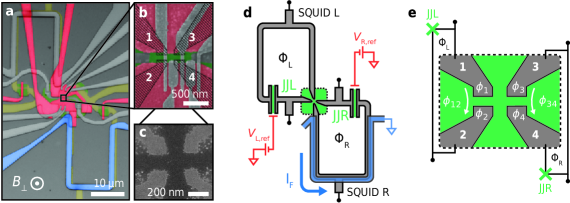
The devices (A and B) are formed in an InSb0.86As0.14 two-dimensional electron gas (2DEG) proximitized by epitaxial aluminum. Selective etching of the Al defines the multiterminal DC SQUID [35], see Figs. 1(a-c). A schematic depiction of the circuit is given in Fig. 1(d). The SQUIDs are designed such that two pairs of terminals in the 4TJJ each form one junction of a DC SQUID (labeled L or R). For each SQUID, the other roughly -wide reference junction (labeled JJL or JJR) is much larger and therefore has a much higher critical current or . In this DC SQUID configuration with asymmetric critical currents, the CPR of each pair of the 4TJJ terminals can be directly measured if the SQUID loop inductance is negligible [36, 37].
Two Ti/Pd layers of gate electrodes were then patterned, separated by a thick AlOx dielectric from the 2DEG and from each other. These include top gates over the reference junctions JJL and JJR of each SQUID applying voltages and respectively. These allow us to pinch off conductance through these junctions and remove the corresponding SQUID’s flux-dependent behavior. Second, a large depletion gate in the first layer surrounding the 4TJJ (red in Fig. 1(b)) allows us to apply a voltage depleting carriers surrounding it and eventually within the junction itself. This gate is kept grounded for all measurements except those in Appendix A where we investigate its behavior. Metallic Ti/Pd probe contacts near the 4TJJ are kept electrically floating or grounded to not interfere with measurements 111 The probes are floating for all measurements except those of Figs. 2(d), 3(c), and 5, where one is grounded. As switching current measurements, these measurements are unaffected by the grounded probes, since current favors traveling through the superconducting circuit until the current bias is large enough that the circuit switches into a resistive state. . Lastly, a NbTiN flux bias line (blue in Figs. 1(a,d)) with critical current was sputtered around SQUID R to locally bias the magnetic flux penetrating it without significantly tuning the flux through SQUID L. All other gates (gray in Figs. 1(a,b)) are kept grounded unless otherwise specified. Combined with a global magnetic field with an almost fully out-of-plane component (calibrated in Appendix B), this allows for independent control of the magnetic flux through both SQUIDs. For additional fabrication details, see Ref. [39]. Measurements are conducted at the 20- base temperature of a dilution refrigerator.
Before proceeding to measurements, we remark that the supercurrent across any two terminals (labeled in Fig. 1e) of the 4TJJ is a -periodic function of all phase differences of their superconducting wave functions [1]. Because only the relative phase differences determine the junction’s behavior, there are only phase degrees of freedom for any -terminal JJ. As we embed the 4TJJ in two DC SQUIDs, we have control of only and , meaning that a third independent phase difference (eg. ) is not directly controlled by experimentally tunable parameters.
To probe any uniquely multiterminal Josephson effects in this 4TJJ, we deduce phase shifts in its CPR through SQUID oscillation measurements, that is, measurements of the CFR. For two-terminal JJs, an established technique for measuring their CPR is to embed the JJ in a DC SQUID containing another ‘reference’ JJ and measure the SQUID’s critical current as a function of flux. When the reference JJ’s critical current is much higher than that of the probed junction the CFR of the SQUID becomes equivalent to the CPR of the probed junction [36, 37, 40]. It is important to note however that in the presence of a small but finite loop inductance, this is not strictly true. Nonetheless, we show that the CFR possesses key properties of the true CPR: its periodicity in flux, and shifts in its phase offset (see Appendix C).
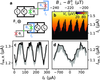
To begin we characterize each SQUID individually, with results summarized in Fig. 2. For these measurements, one SQUID is probed while the other’s leads are kept floating, see Fig. 2(a). To exclude effects from the opposing SQUID, we set or to eliminate conductance through the opposite SQUID’s reference junction. This prevents applied fields from tuning the phase across the opposite SQUID’s 4TJJ terminals. The junctions in these devices have large enough self-capacitances that they are underdamped, potentially from capacitances to the nearby floating 4TJJ terminals. This is signified by varying stochastically between values less than or equal to their critical currents [41, 42]. An example CFR measurement is in Fig. 2(b), where we show switching current oscillations of SQUID L measured with a single current trace upwards from for each value. At several values appears much lower than the overall nearly-sinusoidal trend. We observe that SQUID L exhibits a periodicity of as a function of , expected to be roughly the same for SQUID R as they have identical lithographically-defined loop areas. Since and varies randomly between each trace, we focus on the maximum observed across repeated sweeps. Traces are taken in a positive direction from to ensure the switching current and not retrapping current is measured.
The resulting CFR measurements of SQUIDs L and R as a function of are plotted in Figs. 2(c) and 2(d). SQUID R has a periodicity of roughly one flux quantum per change in while SQUID L has a periodicity of , indicating that the flux-bias line almost exclusively tunes the magnetic flux through SQUID R.
III Flux-Tunable Nonlocal Josephson Effect
We proceed by conducting measurements involving both SQUIDs, aiming to probe nonlocal effects of the phase difference across two terminals of the 4TJJ on the CPR through the other two. To do so, we float the leads of SQUID R but keep JJR conducting unless otherwise specified, measuring the voltage across SQUID L as a function of and . Recall that roughly equally tunes and while almost exclusively tunes (see Figs. 2(c,d)). This means we can fully navigate the space of phase differences and by sweeping these two parameters. Our results are summarized in Fig. 3.
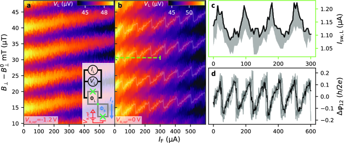
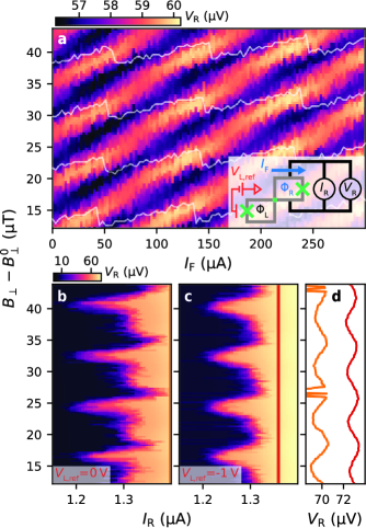
In Figs. 3(a,b) we fix to a value near the SQUID L critical current and measure . The SQUID voltage in its resistive state is a function of its critical current, and so must have the same periodicity and phase offset [41]. Hence, from the positions of extrema in we can extract the relative value of the offset across terminals 1 and 2. When JJR is closed as in Fig. 3(a) so that is not tuned by or , only local SQUID oscillations as a function of are visible, tilted upwards due to the small cross coupling of into . Remarkably however, when as in Fig. 3(b), lobes of SQUID oscillation maxima appear in a zig-zag pattern. The lines of maximum (highlighted in gray) are oriented diagonally along the and axes in a different direction than the maxima lines in Fig. 3(a). This feature thus arises due to a variation in changing . In other words, the supercurrent through terminals 1 and 2 of the 4TJJ is tuned by the phase difference across two completely different terminals of the junction, manifesting a a flux-tunable -junction. Three-terminal circuits of two JJs sharing a common lead have enabled observations of similar nonlocal Josephson effects [43, 33, 34] as well as one controlled by excess spins in the junction [44]. In these experiments, nonlocal coupling between junctions was claimed to arise due to the direct wave function overlap of ABSs in either junction. While these experiments have no obvious analog in four-terminal circuits, the effect observed here may be described as the limit of ABS wave functions in two JJs completely merging together [29]. We compare these experiments further in Sec. IV.
To make this observation concrete, in Fig. 3(c) we measure repeated current traces of SQUID L along the green line highlighted in Fig. 3(b). The maximum observed switching current across all traces is shown as a black line while the variation of is shown in gray. Large oscillations in the switching currents are visible as a function of with the periodicity of SQUID oscillations in SQUID R. Since a change of over in is required to tune by one flux quantum due to direct cross coupling, these SQUID oscillations are purely due to coupling of to the CPR between terminals 1 and 2. Additionally, we quantify the degree to which the offset between terminals 1 and 2 can be tuned in Fig. 3(d). From the positions of successive SQUID oscillation maxima plotted in Fig. 3(b) in white, we extract the relative change of each peak as a function of . Since we can only extract the relative apparent offset of the junction, we arbitrarily define as the maximum position at . A linear offset is also subtracted from each maximum to remove the effect of cross coupling between and , and the result is converted into units of flux quanta from the -periodicity of SQUID L oscillations. The average across all maxima is plotted in black, while individual peak oscillations are in gray. We see that the -junction formed across terminals 1 and 2 can have its phase offset tuned continuously in a range of over . Behavior consistent with this is observed for analogous measurements of SQUID R, shown in Appendix D, and similar effects are also seen in measurements of a second device of identical design in Appendix E.
Importantly, the -periodic circulating current in SQUID R could couple trivially to the flux through SQUID L via the loops’ mutual inductance in the absence of any four-terminal junction effects. Due to the device design maximizing the spatial separation between SQUID loops however (Fig. 1(a)), such a coupling could not cause the observed strength of oscillations in : the magnetic field produced by such loops carrying currents of less than produces less than of a flux quantum in the opposing loop.
IV Multiterminal Junctions as Two-Terminal Junction Arrays
In multiterminal JJs and Andreev molecule devices, tunable -junctions are often considered a signature of behavior distinct to hybridized ABSs [45, 46] or of an ABS spectrum distinctly associated with multiterminal JJs [11]. In this section, we demonstrate that modeling these systems with networks of two-terminal JJs produces a tunable -junction behavior which may be difficult to distinguish from the case where bound states in these junctions are truly hybridized into a multiterminal JJ or an Andreev molecule. Namely, while several superconducting terminals connected to a semiconducting region smaller than the superconducting coherence length is naturally described by a hybridized ABS spectrum [1], similar nontrivial behavior in the CPR is also expected for a network of two-terminal JJs connecting each terminal. As a minimal model, we consider circuits of JJs neglecting linear inductances and capacitive effects, and approximate each junction as possessing a sinusoidal CPR. As examples, we consider a two-terminal JJ network designed to emulate the results measured in Fig. 3(b) and others to reproduce results of recent experiments observing CPRs consistent with Andreev molecule effects [33, 34].
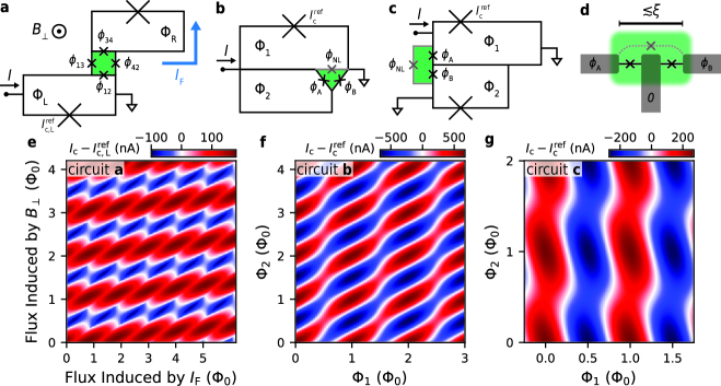
Beginning with the 4TJJ embedded in two asymmetric DC SQUIDs as in this experiment, we model the 4TJJ as four two-terminal JJs of critical current coupling each neighboring superconducting terminal , see Fig. 4(a). From switching current measurements of SQUID L with its reference junction pinched off, we estimate the equivalent critical current between terminals 1 and 2 as , approximating the same between terminals 3 and 4 by symmetry in the device design. Since the distance between terminals 1 and 3 or 2 and 4 is larger, we select to approximate the qualitative behavior of the CFR maxima seen in Fig. 3(b). By applying Kirchhoff’s current law and flux quantization while assuming the flux threading the 4TJJ (green in Fig. 4(a)) is negligible, we can calculate the critical current across SQUID L [47]. Results are shown in Fig. 4(e). While the functional dependence of measured at fixed current in the resistive state is not expected to precisely match the CPR, the simulated critical current exhibits a similar zig-zag pattern in the positions of maximum critical current. This indicates that a tunable -junction alone is not unique to multiterminal JJ behavior. Namely, this demonstrates that while the lithographic design of the devices measured here contain a 4TJJ, the -junction could appear even if the ABSs formed between each pair of terminals were not hybridized with any other ABSs.
As further examples, we model devices expected to host ABSs hybridized into Andreev molecules [45, 46]. These devices consist of two two-terminal JJs of critical current and phase difference sharing a common superconducting lead and separated by a distance on the order of the , depicted in Fig. 4(d). Due to wave function overlap between the ABS in each junction, an Andreev molecular state is expected to form. A stark signature of this state is a phase offset in one junction tunable by the phase difference across the other junction [45, 46]. In practice however, measured CPRs of Andreev molecule devices have formed the two JJs from a common region of semiconducting material [33, 34]. Since their separation is less than the superconducting coherence length, supercurrent could pass between the outer terminals in the absence of any hybridization of the ABSs in the intended junctions.
We thus model the device geometries of Refs. [33] and [34] with the circuits shown in Figs. 4(b) and 4(c) respectively. Nonlocal effects are modeled by a JJ directly coupling the outer leads with phase difference and critical current . Since each pair of leads is expected to support supercurrent in the absence of the remaining lead, this is roughly equivalent to considering the three-terminal junction with hybridization of the ABSs formed in each junction neglected. Specific values of are extracted directly from Refs. [33, 34], while values are chosen to best match their measurements. The resulting simulations are shown in Figs. 4(f) and 4(g). They bear remarkable similarity with the measurements, in particular producing similar -junction tunability to these experiments in the absence of any ABS hybridization. For more details of these calculations, see Appendix F.
Naturally, as these junctions are defined in a region smaller than , hybridization between ABSs in the junctions is expected to have contributed to the measured CPRs [48]. The above modeling shows, however, that the level of ABS hybridization in existing experiments does not yield CPRs easily distinguishable from the case of a non-interacting three-terminal junction. To exclude this trivial coupling between leads in Andreev molecule devices, measuring similar devices designed with no direct path through the semiconductor between the outer superconducting leads rules out this shunting effect. For example, each junction could be formed from different semiconducting nanowires [49, 43]. Importantly, tunneling spectroscopy measurements of the semiconducting region could also reveal an ABS spectrum exhibiting anticrossings indicative of hybridization between the ABSs [45, 29, 31].
V Conclusions & Outlook
We have studied a 4TJJ by embedding it in two asymmetric DC SQUIDs, observing nontrivial properties of the CPR of a 4TJJ. Namely, we were able to measure SQUID oscillations of two pairs of terminals forming the junction and independently tune two of the three independent phase differences controlling it. From these measurements, we observed a nonlocal Josephson effect: two terminals of the 4TJJ behaved as a -junction with a phase offset tunable by the nonlocal flux biasing the phase difference across two independent junction terminals. This tunability had a range exceeding , and allows the 4TJJ to serve as a superconducting current switch [13]. Modeling multiterminal junctions as two-terminal JJ arrays, we also found that -junction effects alone are not sufficient evidence of hybridization between ABSs in the junction.
Future devices with a barrier gate separating the lead pairs could demonstrate for the first time tunable direct wave function overlap between phase-tunable ABSs. Coupling between relatively distant ABSs mediated by supercurrents or photons in a macroscopic circuit has been observed [50, 51], but demonstrating a local coupling would enable the formation of Andreev molecule-based quasiparticle charge qubits [45, 52], or densely-spaced conventional Andreev qubits. Andreev molecule devices where ABSs are coupled with a superconducting lead in between have exhibited hybridization effects [29, 30], but their coupling is fixed by the superconducting lead dimensions [45, 48]. A tunable wave function overlap with directly tunnel-coupled ABSs in JJs provides an alternate mechanism for realizing qubits based on ABSs or Kitaev chains [53], allowing for readout via inductive coupling of resonators to the phase-biased loops containing each JJ [54, 55]. Last and most notably, with control over one more phase difference in the 4TJJ, Weyl singularities in this system’s subgap state spectrum could be probed [3, 56, 7].
Data Availability
Raw data and scripts for plotting the figures in this publication are available from Zenodo [57].
Acknowledgements.
The authors would like to thank O.W.B. Benningshof and J.D. Mensingh for technical assistance with the cryogenic electronics. We would also like to thank M. Coraiola and F. Nichele for input on the manuscript, and A.R. Akhmerov and K. Vilkelis for discussions on theoretical modeling. The authors also acknowledge financial support from Microsoft Quantum and the Dutch Research Council (NWO).Author Contributions
The devices were designed by W.D.H., fabricated by W.D.H. and I.K. using a 2DEG heterostructure provided by D.X., C.T., and M.J.M.. Data was measured, analyzed, and modeled by C.G.P.. I.K. assisted with designing the measurement setup, and S.G. supervised the project. C.G.P. wrote the manuscript with input from all authors.
Appendix A Gate Performance
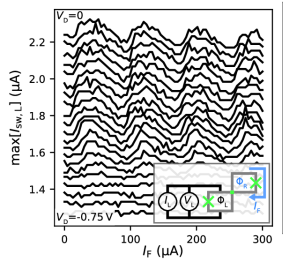
In Fig. 5 we plot a characterization of SQUID L oscillations as a function of the nonlocal flux tuned by in Device A as the central device depletion gate voltage (red in Fig. 1(b)) is swept down from . Repeating multiple current traces at each value, we plot the maximum observed switching current as it is closest to the SQUID critical current. As the gate depletes carriers in the 4TJJ, the amplitude of oscillations decreases until none are observed by . When , the SQUID oscillations are slightly skewed to the left, and this skewness also appears to reduce, leaving the oscillations more sinusoidal at intermediate values. A detailed investigation of the influence of patterned gates on the 4TJJ characteristics was made impossible by the misalignment of gates in the second layer (gray in Fig. 1). These gates were designed to tune the chemical potential selectively between pairs of terminals, enable tunneling spectroscopy with the normal metal probes, and tunably isolate SQUID L from SQUID R.
Appendix B Field Direction Calibration
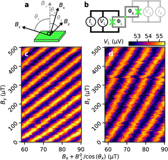
For all measurements in the main text of this manuscript, the external magnetic field used (as opposed to the field generated by the flux current ) was along a three-axis magnet’s ‘x’ direction, mostly out-of-plane of the chip, see Fig. 6(a). To calculate the out-of-plane component as labeled in both figures, we calibrate the field direction with measurements on Device B, summarized in Fig. 6. Measuring SQUID oscillations of SQUID L in its resistive state, akin to the measurements of Figs. 3(a) and 3(b), we extract the periodicity of oscillations along each of the magnets three axes. From these measurements, we infer that the angles for of field with respect to the out-of-plane vector are , , and . This implies that the periodicity of SQUID L with respect to is approximately in Device B, consistent with the devices’ loop areas (see Fig. 1(a)).
As Device A may have been loaded in a different direction with respect to the magnet compared to Device B, these angles are not the same for Device A. Despite this, because Device A has the same lithographical design as Device B, its SQUIDs’ oscillation periodicities are expected to be the same. Hence, from the periodicity of SQUID L extracted from the data of Fig. 3(a) before converting the axis to , we infer for Device A. This enables us to calculate from the applied field.
Appendix C Current-Phase Relations of Four-Terminal Junctions embedded in Asymmetric SQUIDs
On its own, it is impossible to measure the CPR of the 4TJJ because the phase differences across its terminals cannot be controlled. Embedding each pair of terminals (namely and ) from the 4TJJ into a DC SQUID penetrated by magnetic fluxes and allows control of and , respectively, through tuning of these fluxes. Reference junctions JJL and JJR must also be embedded in each SQUID loop to prevent the SQUID’s critical current from being too large to practically measure. In that case, the supercurrent across SQUID L when the other SQUID’s leads are floating is
| (1) |
where is the phase difference across reference junction L/R with critical current , is the critical current of the 4TJJ, and and are some -periodic functions such that [58]. In other words, is the current phase relation of the 4TJJ between leads and , which depends on all phase differences across it.
We assume the other SQUID’s leads are floating so that current into the 4TJJ is conserved. By flux quantization, we have that
| (2) |
where and are the self-inductance and the circulating current around SQUID L/R. Note that must itself be periodic in flux. Because we have that , the phase difference will adjust itself to whichever value maximizes the current flowing through JJL, since this in turn maximizes the SQUID’s critical current. As the 4TJJ by comparison has a negligible effect on the SQUID supercurrent, the phase difference adjusts to the value allowing the flux quantization condition to be satisfied: . Meanwhile, the opposite SQUID has no current bias applied directly across it, and before the circuit critical current is reached, cannot have more than circulating through it. Because , this means must be at a value corresponding to a near zero fraction of its critical current, namely . The critical current of the entire SQUID is then:
| (3) |
When the loop inductances are negligible, note that and are linear in the applied flux, so we can directly control the phase difference across each pair of the 4TJJ’s leads by tuning . Hence, the critical current of the SQUID is equal to the CPR of the 4TJJ across two terminals shifted by the critical current of the reference junction and skewed by non-zero loop inductances and .
Summarily, we have that plus a constant offset. Conservatively estimating that the individual SQUIDs have inductances of and circulating currents bounded by , circulating currents perturb by less than radians. Without knowing precisely, the CFR still possesses key properties of the true CPR due to the periodicity of : its periodicity in flux, and shifts in its phase offset.
Appendix D Nonlocal Flux Dependence in SQUID R
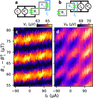
For comparison with Fig. 3, we measure the nonlocal coupling of into the SQUID R oscillations containing the junction formed across terminals 3 and 4, with results summarized in Fig. 7. The manifestation or strength of nonlocal effects is distorted in this case because the parameter tuning the nonlocal flux is , which nearly equally tunes . Conversely, in this case the parameter tuning the local flux has a negligible effect on the nonlocal flux. As in Fig. 3(b), we first fix the current across SQUID R near and measure voltage in Fig. 7(a).
Despite tuning both and , nonlocal features are still visible in Fig. 7(a). Namely, in addition to the expected diagonal oscillations associated with local SQUID R oscillations, the intensity of the voltage oscillations changes periodically with SQUID L’s periodicity. To emphasize this, we plot the positions of SQUID L oscillation maxima extracted from Fig. 3(b) in white, where it aligns with the local maxima in along the diagonal. Additionally, a minor zig-zag perturbation of the SQUID R oscillations from a simple diagonal path is visible, but because of the strong dependence of on both and , it is difficult to quantify the degree to which tunes this junction into a -junction.
To investigate the degree to which four-terminal Josephson effects are present across terminals 3 and 4, we plot full current traces with JJL open (Fig. 7(b)) and closed off (Fig. 7(c)). Each plot is averaged over many and measurements to alleviate effects from instability of the SQUIDs as a function of . Remarkably, when JJL has a finite critical current, lobes in the SQUID oscillations are visible spaced by half the SQUID L periodicity. Conversely, when JJL is closed, these higher harmonic lobes vanish, though the oscillations remain significantly non-sinusoidal. In Fig. 7(a) only -periodic oscillations are visible along both axes, however. Based on existing theories of 4TJJs [11, 12], this behavior is actually expected, and can be thought of as two flux quanta being threaded into the SQUIDs per period of . For such junctions, there are regions of -space where phase slips of the JJ occur due to the appearance of vortex states inside the junction, producing additional local extrema in the CPR along lines of equal and .
Interestingly, these additional extrema in the critical current are not reflected in the voltage measured in the resistive state, emphasized by linecuts in Fig. 7(d). A nearly sinusoidal resistive-state voltage is observed even when , indicating that certain features of the CPR are not noticeably reflected in . From the perspective of a resistively and capacitively shunted junction (RCSJ) model [41], for example, this is possible for an underdamped junction possessing a substantial self-capacitance. Due to the stochastically varying switching current observed in current traces (see the averaged traces of Fig. 2 for example), it is clear that the 4TJJ is underdamped. Nonetheless, we emphasize that the periodicity and phase offset of the fixed-current measurements accurately reflect that of the CPR.
Appendix E Supporting data on a Second Device
Here we present a second set of nonlocal SQUID oscillation measurements akin to those in Fig. 3(b) and Fig. 7(a) on another device (Device B), with results shown in Fig. 8. This device has an identical design to Device A and was fabricated on the same chip. Measurements for both SQUID L and SQUID R are presented in Figs. 8(c) and 8(d), respectively. The corresponding measurement circuits are shown in Figs. 8(a,b). In these measurements, with the opposite SQUID’s leads floating, we observe -periodic oscillations in primarily as a function of and in both as a function of and , consistent with the flux-bias line almost exclusively affecting by design. In addition to the small direct cross coupling of to giving the SQUID L oscillations a slight tilt in Fig. 8(c), periodic oscillations in the peak height are observed as a function of . The oscillations also exhibit a slight zig-zag pattern comparable to those of Device A seen in Fig. 3, but due to the significant jitter visible in the measurements, extracting a shift of the junction is difficult. The measurements of SQUID R are also qualitatively similar to those of Device A.
Appendix F Two-terminal Junction Array Models of Multiterminal Junctions
Herein we derive expressions for the critical current of the four- and three-terminal JJ circuits shown in Fig. 4(a-c) by maximizing the supercurrent carried through the terminal labeled with an input current . In both cases, we assume that the flux threading the multi-terminal JJ is negligible. We also assume that the reference junction critical currents are much larger than the critical currents of all two-terminal JJs describing the multiterminal JJ. For simplicity we neglect capacitances and linear inductances, and assume all junctions have CPRs of the form where is the phase difference across the junction.
We begin with the Andreev molecule device of Fig. 4(b), which is designed to contain two JJs sharing a common superconducting terminal and separated by a distance on the order of the superconducting coherence length , see Fig. 4(d). To separately control the phase differences across each junction, the two junctions are embedded in loops threaded by fluxes and (in units of ). Lastly, in one of the loops a reference junction of large critical current is embedded to measure one of the JJ’s CPRs. As these devices in previous experiments have been formed by connecting three superconducting contacts to a continuous region of conducting semiconducting material smaller than the coherence length [33, 34], it is feasible that supercurrent can directly travel between the two outermost terminals even in the absence of a central terminal. Consequently, we model the nonlocal coupling between the two JJs as a third JJ connecting the two outer terminals while bypassing the central one (gray in Fig. 4(d). Notably, this model does not include wave function overlap between ABSs from different individual junctions.
Given the phase differences across the junctions as defined in Fig. 4(c), by flux quantization we have that . Next, since the critical current of the reference junction is very large compared to all others, its phase difference will adjust to whichever value maximizes the supercurrent through it, in this case . Finally, by flux quantization we then have that and . The signs of the phase differences are determined by an arbitrary but consistent definition of the current direction through each circuit branch [47], with fluxes defined as being associated with a clockwise current through a given loop. Accordingly, the critical current of the circuit is
| (4) |
Notably, the decision to approximate the flux producing a phase difference across the shunting junction as opposed to directly tuning was somewhat arbitrary. Modeling the circuit as the shunting junction existing out-of-plane such that tunes produces the same result as in eq. 4 except shifted by along the axis.
Proceeding to the circuit of Fig. 4(d) representing the device geometry of Ref. [34], we conduct similar calculations using flux quantization rules. In this case, there are reference junctions of critical currents and in the - and -threaded loops, respectively. With current being passed into the top left port and the others grounded, maximizing the supercurrent requires maximizing the current through reference junction 1, since we assume the reference junctions have arbitrarily large critical current. Hence, its phase will tend to . For the other reference junction, it is connected to grounded terminals on both sides and so is not a bottleneck for the device’s critical current. We can thus take the limit of infinite critical current such that no phase drop occurs across this junction, and we have . Other flux quantization loops yield and . Hence, by calculating the current through each circuit branch connecting to the input, we find the device critical current to be
| (5) |
Lastly, we consider the 4TJJ circuit of Fig. 4(a). Again, there are reference junctions of large critical currents and in the loops threaded by and . The current flows through the branches containing reference junction L, the junction between terminals 1 and 2, and the junction between terminals 1 and 3. Since is assumed very large, its phase at the critical current by the same reasoning as before is roughly . Again, as in the previous case we can take since it is not a bottleneck for the critical current. From flux quantization, we then obtain , , and . To obtain enough equations to solve for all phases, we note that by Kirchhoff’s current law we have . Solving the last flux quantization condition for and substituting the result into the current conservation equation, we obtain
| (6) |
This is a transcendental equation and has multiple solutions between . The critical current of the circuit is by definition the maximum possible supercurrent it can sustain, so for every value we choose the -dependent solution to eq. 6 which maximizes . The critical current of the circuit is then the sum of the current through the three paths branching from the input current , given as
| (7) |
For the calculated results in Fig. 4(e), we plot them as a function of the flux generated by and , considering cross coupling of into SQUID L determined from the oscillation periodicities of Fig. 2. The axis is converted into units of by defining as a single flux quantum threading SQUID R due to as well as the resulting cross coupling to SQUID L. For , is defined as a single flux quantum threading both SQUIDs.
References
- Beenakker [1991] C. W. J. Beenakker, Universal limit of critical-current fluctuations in mesoscopic Josephson junctions, Physical Review Letters 67, 3836 (1991).
- van Heck et al. [2014] B. van Heck, S. Mi, and A. R. Akhmerov, Single fermion manipulation via superconducting phase differences in multiterminal Josephson junctions, Physical Review B 90, 10.1103/physrevb.90.155450 (2014).
- Riwar et al. [2016] R.-P. Riwar, M. Houzet, J. S. Meyer, and Y. V. Nazarov, Multi-terminal josephson junctions as topological matter, Nature Communications 7, 10.1038/ncomms11167 (2016).
- Xie et al. [2017] H.-Y. Xie, M. G. Vavilov, and A. Levchenko, Topological andreev bands in three-terminal josephson junctions, Physical Review B 96, 10.1103/physrevb.96.161406 (2017).
- Houzet and Meyer [2019] M. Houzet and J. S. Meyer, Majorana-Weyl crossings in topological multiterminal junctions, Physical Review B 100, 10.1103/physrevb.100.014521 (2019).
- Fatemi et al. [2021] V. Fatemi, A. R. Akhmerov, and L. Bretheau, Weyl Josephson circuits, Physical Review Research 3, 10.1103/physrevresearch.3.013288 (2021).
- Barakov and Nazarov [2023] H. Barakov and Y. V. Nazarov, Abundance of Weyl points in semiclassical multiterminal superconducting nanostructures, Physical Review B 107, 10.1103/physrevb.107.014507 (2023).
- Meyer and Houzet [2017] J. S. Meyer and M. Houzet, Nontrivial Chern Numbers in Three-Terminal Josephson Junctions, Physical Review Letters 119, 10.1103/physrevlett.119.136807 (2017).
- de Bruyn Ouboter et al. [1995] R. de Bruyn Ouboter, A. Omelyanchouk, and E. Vol, Multi-terminal SQUID controlled by the transport current, Physica B: Condensed Matter 205, 153 (1995).
- Zareyan and Omelyanchuk [1999] M. Zareyan and A. N. Omelyanchuk, Coherent current states in a mesoscopic four-terminal Josephson junction, Low Temperature Physics 25, 175 (1999).
- Omelyanchouk and Zareyan [2000] A. Omelyanchouk and M. Zareyan, Ballistic four-terminal Josephson junction: bistable states and magnetic flux transfer, Physica B: Condensed Matter 291, 81 (2000).
- Amin et al. [2001] M. H. S. Amin, A. N. Omelyanchouk, and A. M. Zagoskin, Mesoscopic multiterminal Josephson structures. I. Effects of nonlocal weak coupling, Low Temperature Physics 27, 616 (2001).
- Alidoust et al. [2012] M. Alidoust, G. Sewell, and J. Linder, Superconducting phase transistor in diffusive four-terminal ferromagnetic Josephson junctions, Physical Review B 85, 10.1103/physrevb.85.144520 (2012).
- Amin et al. [2002] M. Amin, A. Omelyanchouk, A. Blais, A. M. van den Brink, G. Rose, T. Duty, and A. Zagoskin, Multi-terminal superconducting phase qubit, Physica C: Superconductivity 368, 310 (2002).
- Vleeming et al. [1996] B. Vleeming, A. Zakarian, A. Omelyanchouk, and R. de Bruyn Ouboter, Macroscopic quantum interference phenomena in a 4-terminal SQUID, Physica B: Condensed Matter 226, 253 (1996).
- Vleeming et al. [1999] B. Vleeming, F. van Bemmelen, M. Berends, R. B. Ouboter, and A. Omelyanchouk, Measurements of the flux, embraced by the ring of a four-terminal SQUID, as a function of the external magnetic flux and the applied transport current, Physica B: Condensed Matter 262, 296 (1999).
- Draelos et al. [2019] A. W. Draelos, M.-T. Wei, A. Seredinski, H. Li, Y. Mehta, K. Watanabe, T. Taniguchi, I. V. Borzenets, F. Amet, and G. Finkelstein, Supercurrent Flow in Multiterminal Graphene Josephson Junctions, Nano Letters 19, 1039 (2019).
- Pankratova et al. [2020] N. Pankratova, H. Lee, R. Kuzmin, K. Wickramasinghe, W. Mayer, J. Yuan, M. G. Vavilov, J. Shabani, and V. E. Manucharyan, Multiterminal josephson effect, Physical Review X 10, 10.1103/physrevx.10.031051 (2020).
- Graziano et al. [2020] G. V. Graziano, J. S. Lee, M. Pendharkar, C. J. Palmstrøm, and V. S. Pribiag, Transport studies in a gate-tunable three-terminal Josephson junction, Physical Review B 101, 10.1103/physrevb.101.054510 (2020).
- Arnault et al. [2021] E. G. Arnault, T. F. Q. Larson, A. Seredinski, L. Zhao, S. Idris, A. McConnell, K. Watanabe, T. Taniguchi, I. Borzenets, F. Amet, and G. Finkelstein, Multiterminal inverse AC josephson effect, Nano Letters 21, 9668 (2021).
- Graziano et al. [2022] G. V. Graziano, M. Gupta, M. Pendharkar, J. T. Dong, C. P. Dempsey, C. Palmstrøm, and V. S. Pribiag, Selective control of conductance modes in multi-terminal josephson junctions, Nature Communications 13, 10.1038/s41467-022-33682-2 (2022).
- Lee [2022] H. Lee, Supercurrent and Andreev bound states in multi-terminal Josephson junctions, Ph.D. thesis, University of Maryland (2022).
- Chiles et al. [2023] J. Chiles, E. G. Arnault, C.-C. Chen, T. F. Q. Larson, L. Zhao, K. Watanabe, T. Taniguchi, F. Amet, and G. Finkelstein, Nonreciprocal Supercurrents in a Field-Free Graphene Josephson Triode, Nano Letters 23, 5257 (2023).
- Pfeffer et al. [2014] A. H. Pfeffer, J. E. Duvauchelle, H. Courtois, R. Mélin, D. Feinberg, and F. Lefloch, Subgap structure in the conductance of a three-terminal josephson junction, Physical Review B 90, 10.1103/physrevb.90.075401 (2014).
- Cohen et al. [2018] Y. Cohen, Y. Ronen, J.-H. Kang, M. Heiblum, D. Feinberg, R. Mélin, and H. Shtrikman, Nonlocal supercurrent of quartets in a three-terminal Josephson junction, Proceedings of the National Academy of Sciences 115, 6991 (2018).
- Huang et al. [2022] K.-F. Huang, Y. Ronen, R. Mélin, D. Feinberg, K. Watanabe, T. Taniguchi, and P. Kim, Evidence for 4e charge of Cooper quartets in a biased multi-terminal graphene-based Josephson junction, Nature Communications 13, 10.1038/s41467-022-30732-7 (2022).
- Zhang et al. [2023] F. Zhang, A. S. Rashid, M. T. Ahari, W. Zhang, K. M. Ananthanarayanan, R. Xiao, G. J. de Coster, M. J. Gilbert, N. Samarth, and M. Kayyalha, Andreev processes in mesoscopic multiterminal graphene josephson junctions, Physical Review B 107, 10.1103/physrevb.107.l140503 (2023).
- Gupta et al. [2023] M. Gupta, G. V. Graziano, M. Pendharkar, J. T. Dong, C. P. Dempsey, C. Palmstrøm, and V. S. Pribiag, Gate-tunable superconducting diode effect in a three-terminal Josephson device, Nature Communications 14, 10.1038/s41467-023-38856-0 (2023).
- Coraiola et al. [2023a] M. Coraiola, D. Z. Haxell, D. Sabonis, H. Weisbrich, A. E. Svetogorov, M. Hinderling, S. C. ten Kate, E. Cheah, F. Krizek, R. Schott, W. Wegscheider, J. C. Cuevas, W. Belzig, and F. Nichele, Phase-engineering the andreev band structure of a three-terminal josephson junction, Nature Communications 14, 10.1038/s41467-023-42356-6 (2023a).
- Matsuo et al. [2023] S. Matsuo, T. Imoto, T. Yokoyama, Y. Sato, T. Lindemann, S. Gronin, G. C. Gardner, S. Nakosai, Y. Tanaka, M. J. Manfra, and S. Tarucha, Phase-dependent Andreev molecules and superconducting gap closing in coherently coupled Josephson junctions, http://arxiv.org/abs/2303.10540 (2023).
- Coraiola et al. [2023b] M. Coraiola, D. Z. Haxell, D. Sabonis, M. Hinderling, S. C. ten Kate, E. Cheah, F. Krizek, R. Schott, W. Wegscheider, and F. Nichele, Spin-degeneracy breaking and parity transitions in three-terminal Josephson junctions, http://arxiv.org/abs/2307.06715 (2023b).
- Buzdin [2008] A. Buzdin, Direct coupling between magnetism and superconducting current in the josephson junction, Phys. Rev. Lett. 101, 107005 (2008).
- Haxell et al. [2023a] D. Z. Haxell, M. Coraiola, M. Hinderling, S. C. ten Kate, D. Sabonis, A. E. Svetogorov, W. Belzig, E. Cheah, F. Krizek, R. Schott, W. Wegscheider, and F. Nichele, Demonstration of the Nonlocal Josephson Effect in Andreev Molecules, Nano Letters 23, 7532 (2023a).
- Matsuo et al. [2023] S. Matsuo, T. Imoto, T. Yokoyama, Y. Sato, T. Lindemann, S. Gronin, G. C. Gardner, M. J. Manfra, and S. Tarucha, Engineering of anomalous Josephson effect in coherently coupled Josephson junctions, http://arxiv.org/abs/2305.06596 (2023).
- Moehle et al. [2021] C. M. Moehle, C. T. Ke, Q. Wang, C. Thomas, D. Xiao, S. Karwal, M. Lodari, V. van de Kerkhof, R. Termaat, G. C. Gardner, G. Scappucci, M. J. Manfra, and S. Goswami, InSbAs Two-Dimensional Electron Gases as a Platform for Topological Superconductivity, Nano Letters 21, 9990 (2021).
- Miyazaki et al. [2006] H. Miyazaki, A. Kanda, and Y. Ootuka, Current-phase relation of a superconducting quantum point contact, Physica C: Superconductivity and its Applications 437-438, 217 (2006).
- Rocca et al. [2007] M. L. D. Rocca, M. Chauvin, B. Huard, H. Pothier, D. Esteve, and C. Urbina, Measurement of the Current-Phase Relation of Superconducting Atomic Contacts, Physical Review Letters 99, 10.1103/physrevlett.99.127005 (2007).
- Note [1] The probes are floating for all measurements except those of Figs. 2(d), 3(c), and 5, where one is grounded. As switching current measurements, these measurements are unaffected by the grounded probes, since current favors traveling through the superconducting circuit until the current bias is large enough that the circuit switches into a resistive state.
- Prosko et al. [2023] C. G. Prosko, I. Kulesh, M. Chan, L. Han, D. Xiao, C. Thomas, M. J. Manfra, S. Goswami, and F. K. Malinowski, Flux-Tunable Hybridization in a Double Quantum Dot Interferometer, 2303.04144 (2023).
- Nanda et al. [2017] G. Nanda, J. L. Aguilera-Servin, P. Rakyta, A. Kormányos, R. Kleiner, D. Koelle, K. Watanabe, T. Taniguchi, L. M. K. Vandersypen, and S. Goswami, Current-Phase Relation of Ballistic Graphene Josephson Junctions, Nano Letters 17, 3396 (2017).
- Tinkham [1996] M. Tinkham, Introduction to superconductivity, 2nd ed. (Dover publications, inc., 1996).
- Haxell et al. [2023b] D. Haxell, E. Cheah, F. Křížek, R. Schott, M. Ritter, M. Hinderling, W. Belzig, C. Bruder, W. Wegscheider, H. Riel, and F. Nichele, Measurements of Phase Dynamics in Planar Josephson Junctions and SQUIDs, Physical Review Letters 130, 10.1103/physrevlett.130.087002 (2023b).
- Matsuo et al. [2022] S. Matsuo, J. S. Lee, C.-Y. Chang, Y. Sato, K. Ueda, C. J. Palmstrøm, and S. Tarucha, Observation of nonlocal Josephson effect on double InAs nanowires, Communications Physics 5, 10.1038/s42005-022-00994-0 (2022).
- Strambini et al. [2020] E. Strambini, A. Iorio, O. Durante, R. Citro, C. Sanz-Fernández, C. Guarcello, I. V. Tokatly, A. Braggio, M. Rocci, N. Ligato, V. Zannier, L. Sorba, F. S. Bergeret, and F. Giazotto, A Josephson phase battery, Nature Nanotechnology 15, 656 (2020).
- Pillet et al. [2019] J.-D. Pillet, V. Benzoni, J. Griesmar, J.-L. Smirr, and Ç. Ö. Girit, Nonlocal Josephson Effect in Andreev Molecules, Nano Letters 19, 7138 (2019).
- Kocsis et al. [2023] M. Kocsis, Z. Scherübl, G. Fülöp, P. Makk, and S. Csonka, Strong nonlocal tuning of the current-phase relation of a quantum dot based Andreev molecule, http://arxiv.org/abs/2303.14842 (2023).
- Rasmussen et al. [2021] S. Rasmussen, K. Christensen, S. Pedersen, L. Kristensen, T. Bækkegaard, N. Loft, and N. Zinner, Superconducting Circuit Companion—an Introduction with Worked Examples, PRX Quantum 2, 10.1103/prxquantum.2.040204 (2021).
- Kornich et al. [2020] V. Kornich, H. S. Barakov, and Y. V. Nazarov, Overlapping andreev states in semiconducting nanowires: Competition of one-dimensional and three-dimensional propagation, Physical Review B 101, 10.1103/physrevb.101.195430 (2020).
- Kürtössy et al. [2021] O. Kürtössy, Z. Scherübl, G. Fülöp, I. E. Lukács, T. Kanne, J. Nygård, P. Makk, and S. Csonka, Andreev Molecule in Parallel InAs Nanowires, Nano Letters 21, 7929 (2021).
- Pita-Vidal et al. [2023] M. Pita-Vidal, J. J. Wesdorp, L. J. Splitthoff, A. Bargerbos, Y. Liu, L. P. Kouwenhoven, and C. K. Andersen, Strong tunable coupling between two distant superconducting spin qubits, http://arxiv.org/abs/2307.15654 (2023).
- Cheung et al. [2023] L. Y. Cheung, R. Haller, A. Kononov, C. Ciaccia, J. H. Ungerer, T. Kanne, J. Nygård, P. Winkel, T. Reisinger, I. M. Pop, A. Baumgartner, and C. Schönenberger, Photon-mediated long range coupling of two Andreev level qubits, 2310.15995 (2023).
- Geier et al. [2023] M. Geier, R. S. Souto, J. Schulenborg, S. Asaad, M. Leijnse, and K. Flensberg, A fermion-parity qubit in a proximitized double quantum dot, 2307.05678 (2023).
- Fulga et al. [2013] I. C. Fulga, A. Haim, A. R. Akhmerov, and Y. Oreg, Adaptive tuning of Majorana fermions in a quantum dot chain, New Journal of Physics 15, 045020 (2013).
- Zazunov et al. [2003] A. Zazunov, V. S. Shumeiko, E. N. Bratus’, J. Lantz, and G. Wendin, Andreev level qubit, Physical Review Letters 90, 10.1103/physrevlett.90.087003 (2003).
- Janvier et al. [2015] C. Janvier, L. Tosi, L. Bretheau, Ç. O. Girit, M. Stern, P. Bertet, P. Joyez, D. Vion, D. Esteve, M. F. Goffman, H. Pothier, and C. Urbina, Coherent manipulation of andreev states in superconducting atomic contacts, Science 349, 1199 (2015).
- Xie et al. [2018] H.-Y. Xie, M. G. Vavilov, and A. Levchenko, Weyl nodes in andreev spectra of multiterminal josephson junctions: Chern numbers, conductances, and supercurrents, Physical Review B 97, 10.1103/physrevb.97.035443 (2018).
- Christian G. Prosko and Wietze D. Huisman and Ivan Kuleshand Di Xiao and Candice Thomas and Michael J. Manfra and Srijit Goswami [2023] Christian G. Prosko and Wietze D. Huisman and Ivan Kuleshand Di Xiao and Candice Thomas and Michael J. Manfra and Srijit Goswami, Data repository accompanying “Flux-tunable Josephson Effect in a Four-Terminal Junction”, https://doi.org/10.5281/zenodo.10212998 (2023).
- Golubov et al. [2004] A. A. Golubov, M. Y. Kupriyanov, and E. Il’ichev, The current-phase relation in josephson junctions, Reviews of Modern Physics 76, 411 (2004).